Structural Modelling using Etabs 2018
Structural Modeling of Residential Building using Etabs 2018.
Aim:
To Model and Analyze the G+7 residential building from the given architectural drawings using the Etabs 2018.
Introduction:
- ETABS is an engineering software product that caters to multi-storey building analysis and design.
- Modelling tools and templates, code-based load prescriptions, analysis methods and solution techniques, all coordinate with the grid-like geometry unique to this class of structure.
- Basic or advanced systems under static or dynamic conditions may be evaluated using Etabs.
- Etabs modeling is the generalization that multi-storey buildings typically consistent od identical or similar floor plans that repeat in the vertical direction.
- Modeling features that streamline analytical model generation and simulate advanced seismic systems.
- Once modeling is complete, Etabs automatically generates and assigns code-based loading conditions for gravity seismic, wind and thermal forces.
Objective:
- To model a residential building with all seismic considerations, based on given architectural inputs.
- To know how to check the seismic performance of a residential building using ETABS.
Given Architectural Residential building Parking area,Typical Floor plan & Elevation.
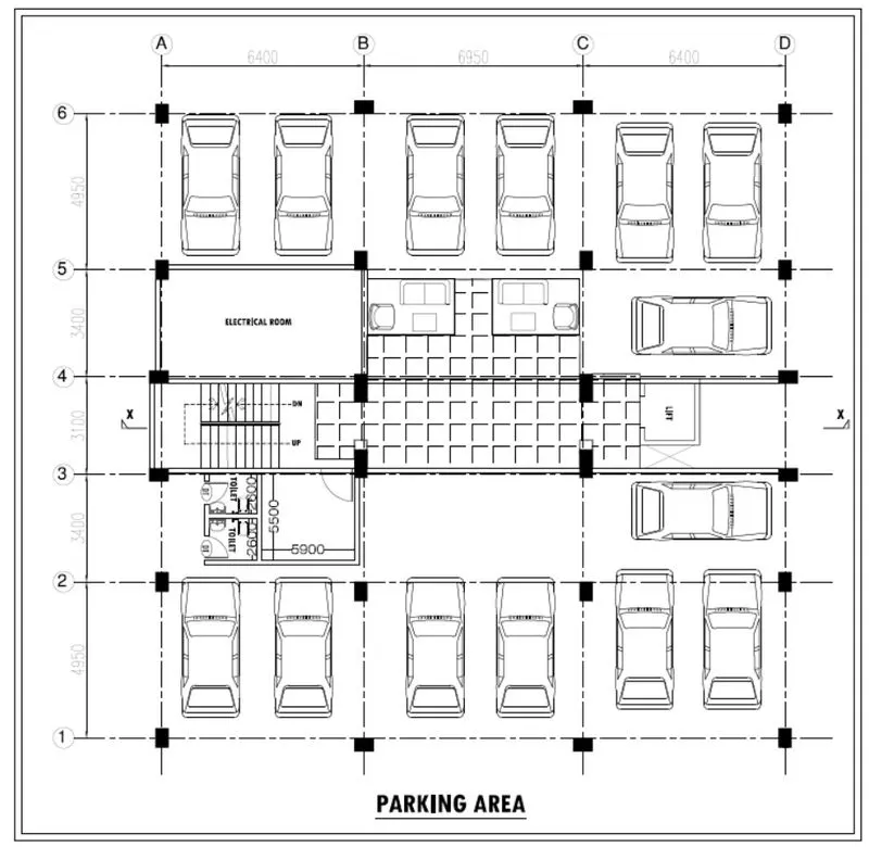
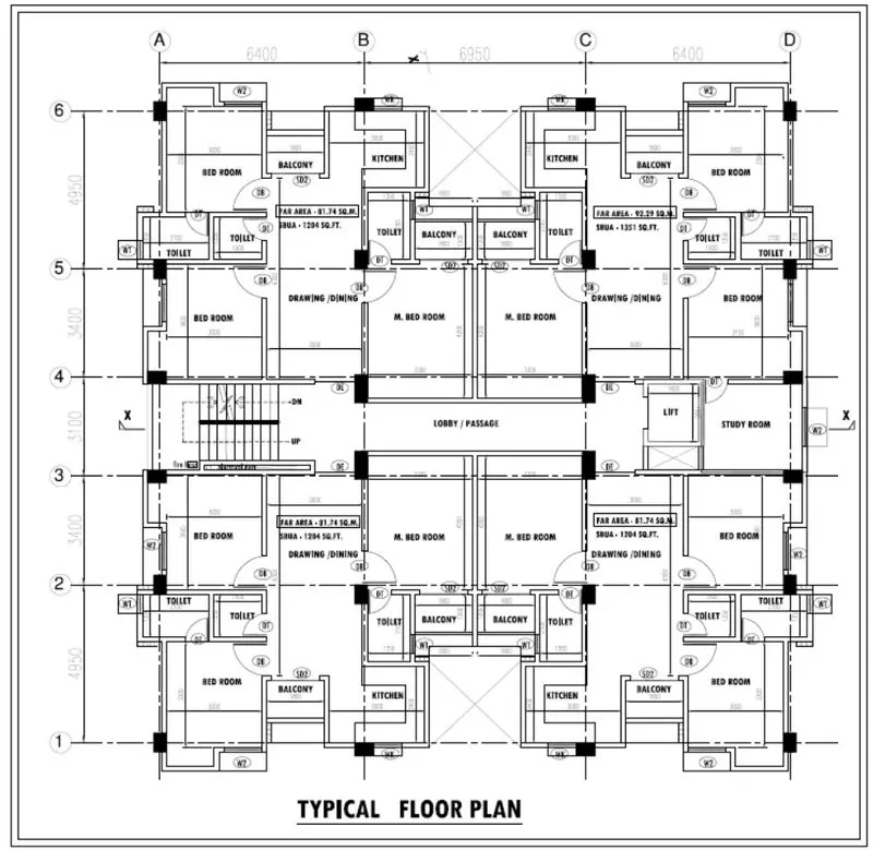
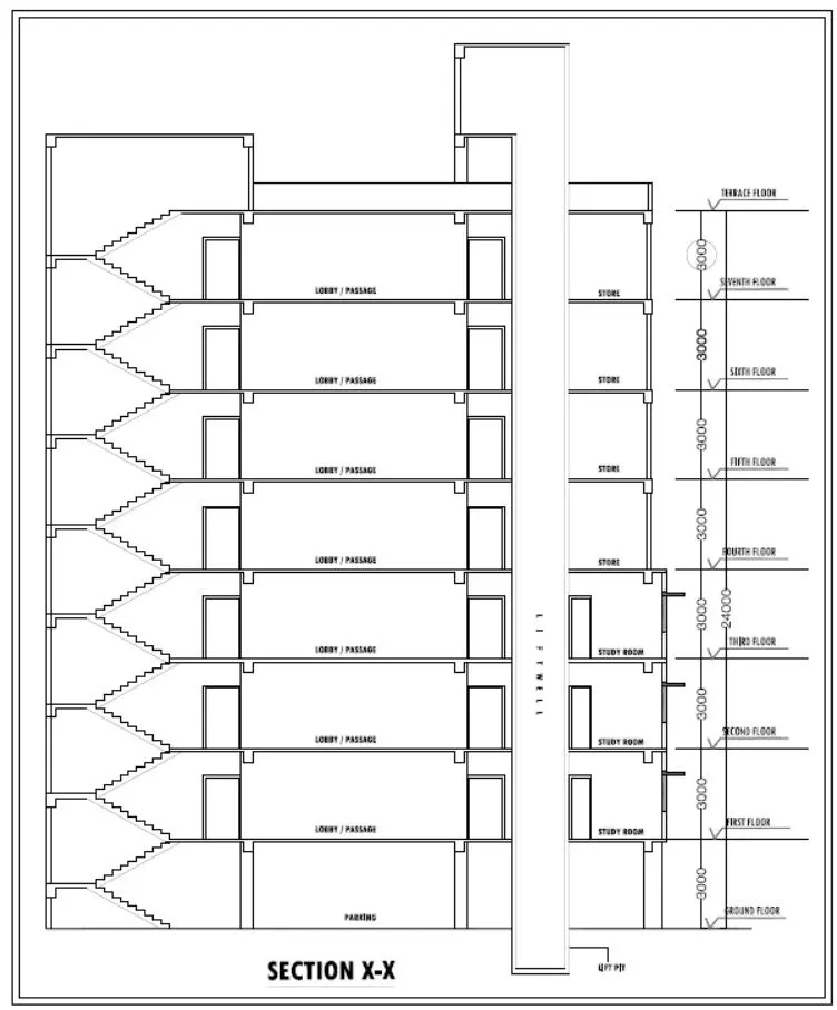
Consideration of Residential building before analysis.
- Cutout check & modification on either sides.
- Vertical irregualrity- Ground floor is dedicated to only car parking, first floor to seventh floor is residential apartments (soft storey).
- planar irregularity- it looks symmetrical, no issue with this.
- The given foot print Area is 391 sq.m, excluding with openings.
- 2% shear wall area w.r.t building area to be taken as per IS 1893.
- So 391x2% = 7.8 sq.m.
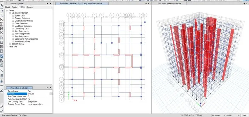
- 16 No:off shear walls with 8.8sq.m area is taken.
- Stiffness modifier for column is 0.7,& for beam 0.35 is taken into consideration.
Significance to remember while modeling.
- In Ground floor no wall, no slab.
- As per engineer intent proper end releases in beams to be taken.
- Comparing static & dynamic forces & revising the factor.
Procedure:
Open ETABS & setup the model.
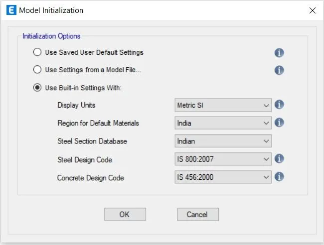
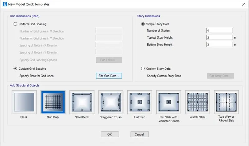
- Once the software is up & running, click on the new model option.
- Once you click on the new model, a dialogue box will pop up where you can set up the codes and units to be used in your project.
Setting up the Grid data.
- To setup the grid data, you need to click on the custom grid option.
- Once you do that, a menu with all the grid settings will open up.
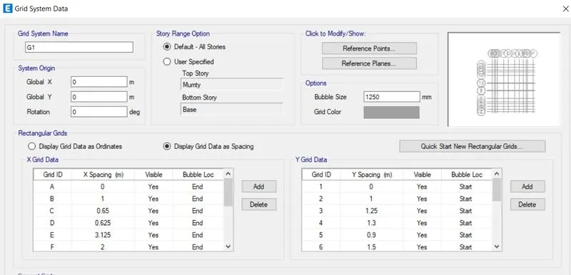
- In the same menu, you can fix the length, numbers of grids in both the orthogonal directions, spacing b/w all the vertical & horizontal grids etc,
- So, by following the same approach, we have setup a display grid data as spacing, as shown below.
Fixing the storey data.
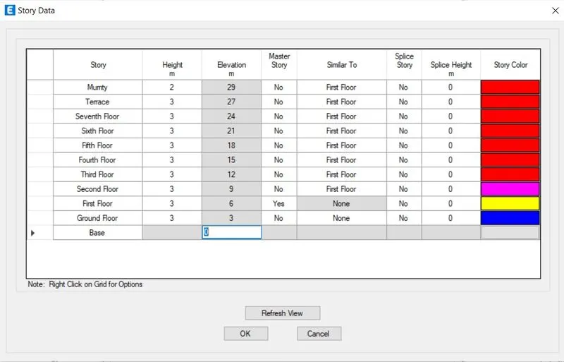
- Similarly, to what we did while setting up the grids, click on the custom storey data option.
- Then, specify the base level, plinth level, height of each floor, & the no:of floors to be included in the model.
- We have arranged for a G+7 Residential building with a 3m height from base to Mumty level.
- Also, you need to fix a master storey and all the similar storeys in the same menu.
- First Floor is master & all other remaining floors are similar storeys.
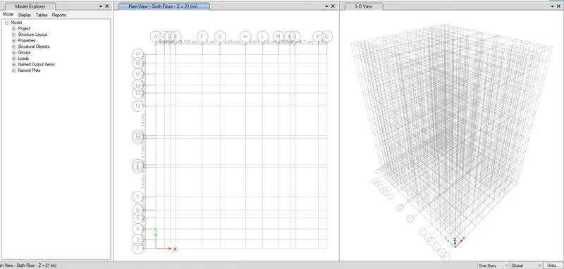
- Once, you do this, model is set to be executed in ETABS with the grid & storeys as specified.
3D view of Grids G+7 Residential building.
Defining the Material Properties.
- It is important to set details of the materials you are going to use for the project in ETABS.
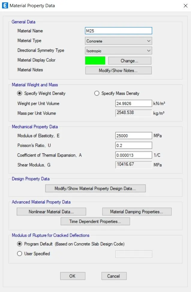
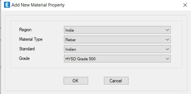
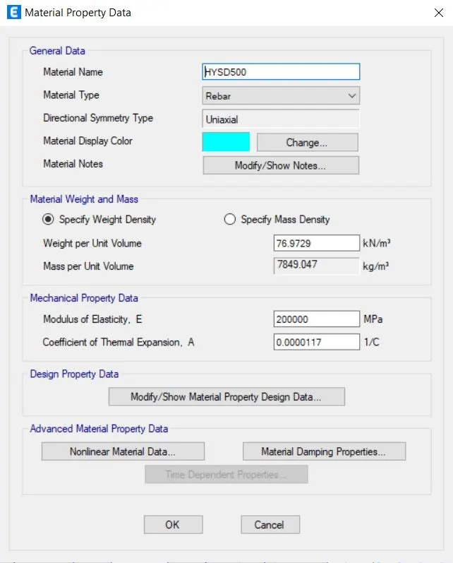
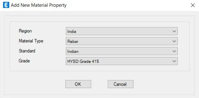
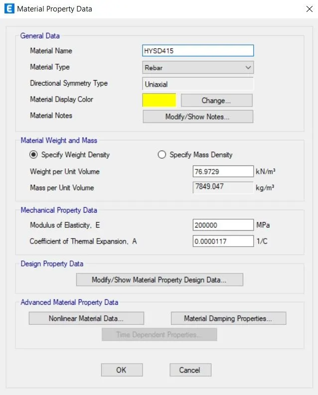
- We have to use M25 grade concrete and HYSD500, HYSD415 steel as per the specifications.
- So, in order to define the same, go to define > material properties > add new > concrete/steel > grade > ok.
- However, since we have already specified the Indian standard codes of practices, the M25 concrete and 500, 450 steel is added by default into the project.
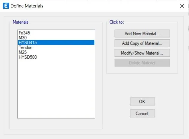
M25 Concrete grade:
HYSD500 and HYSD415 Rebar:
Defining section properties.
- We are using the rectangular concrete sections for all the structural elements like beams, columns, and slabs.
- So, we need to define that in ETABS software so that it allows us to use these sections repeatedly throughout the project.
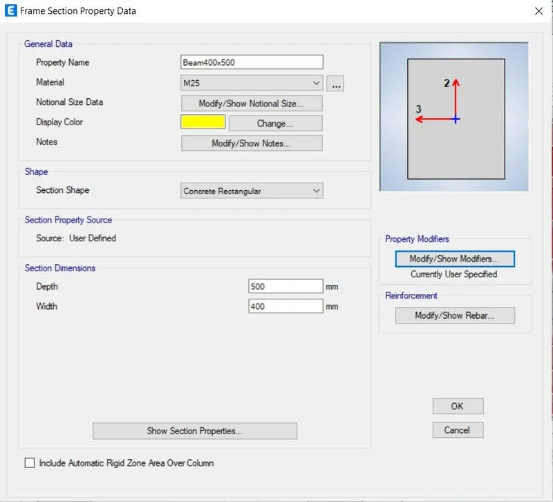
- Go to define > section properties > frame sections > concrete rectangular.
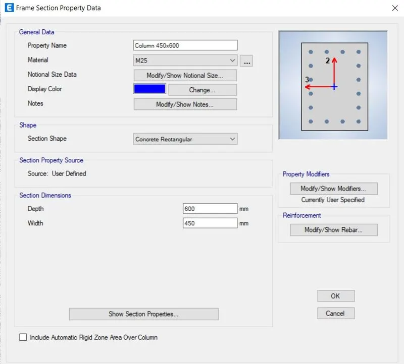
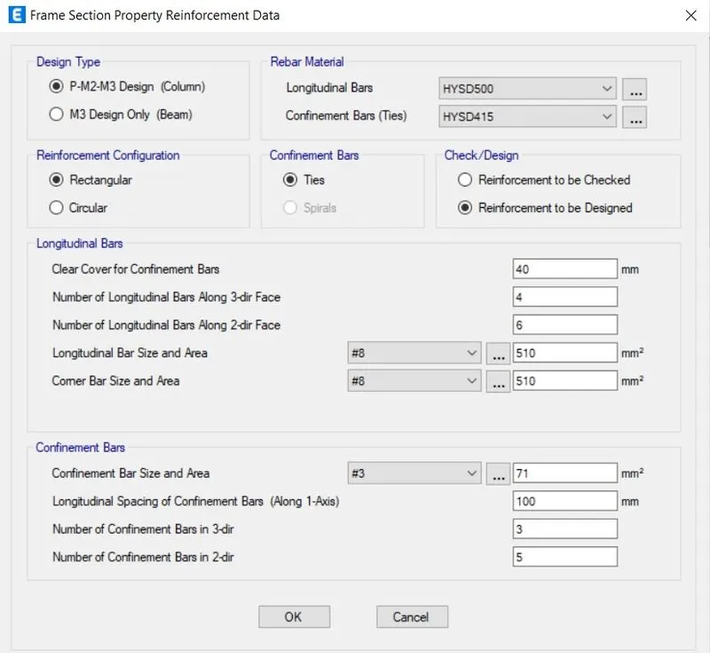
- Then, a dialogue box will appear on your ETABS screen where you can specify the column/beam dimensions and the type of reinforcement (HYSD 415) to be used in the model.
- So, you can define both columns and beams from the same menu.
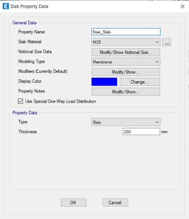
- Now, to define the slab section, again go to define > section > slab.
- Again, a menu will open up where you need to set the slab specifications required for the project.
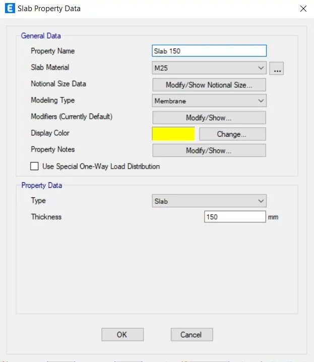
- Here, you need to specify the slab thickness as 150mm & the section as a membrane.
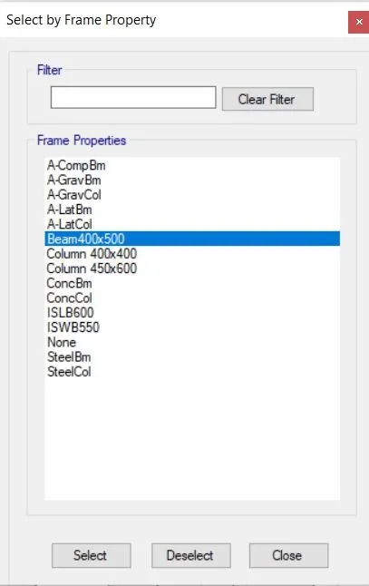
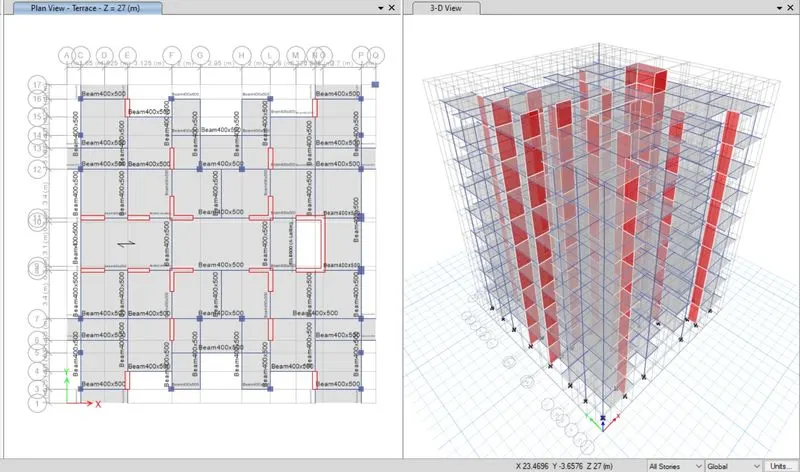
BEAM 400 x 500 mm
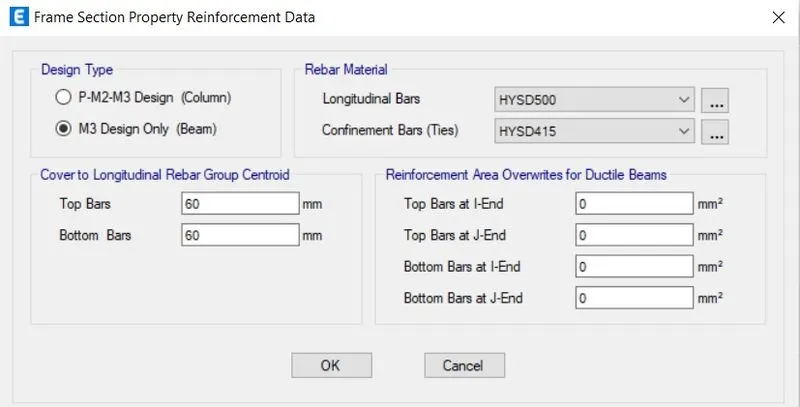
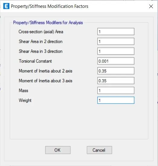
COLUMN 400x400 mm
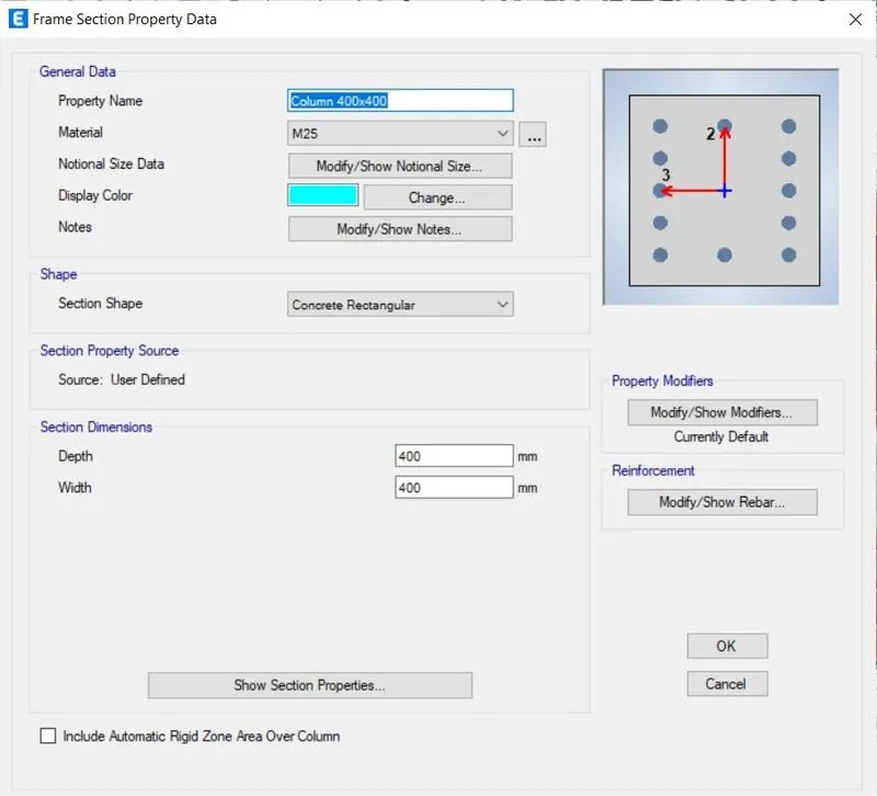
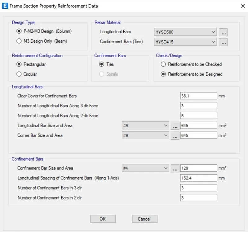
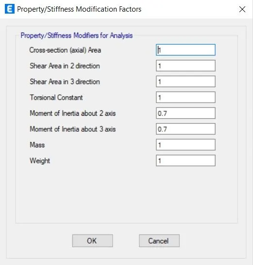
COLUMN 450x600 mm
SLAB 150 mm
STAIR SLAB 200 mm
Execute the Modeling.
- Now that we have defined everything from materials to beams, columns & slabs to be needed for our structure, we can go ahead and draw each structural element as per the specifications.
- We can use the commands in ETABS named quick draw tool.
- As the name suggests, you can draw all the beams, floors & columns with the help of this tool.
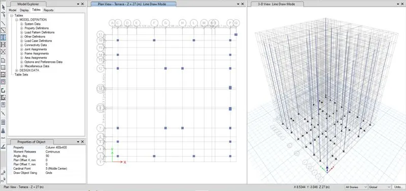
- Select the relative tool that is quick draw columns for drawing columns and vice versa, then choose the section from the dropdown list.
- Then, simply go to the grid system in plan view and start clicking on the grid locations where you want to build these structural elements.
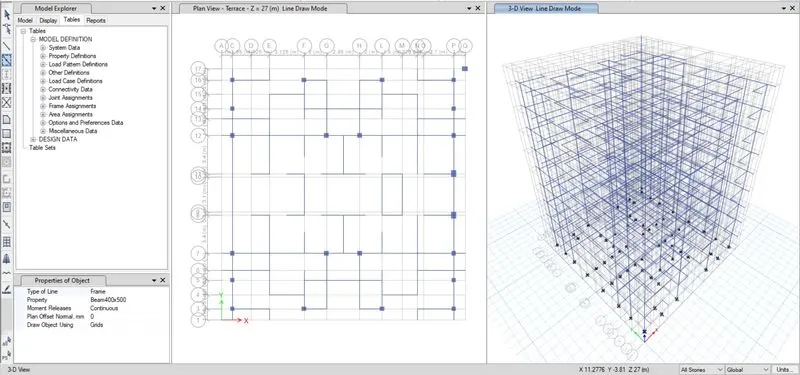
- So, the same approach was followed and the following beams, floors & slabs were drawn in our ETABS model.
Quick draw columns
Quick draw beams
Quick draw shear walls
Quick draw floors
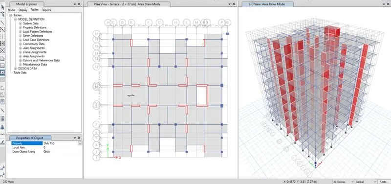
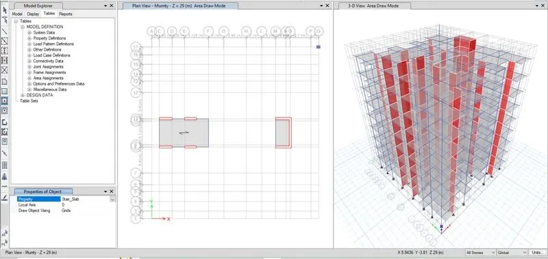
Complete Model in 3D
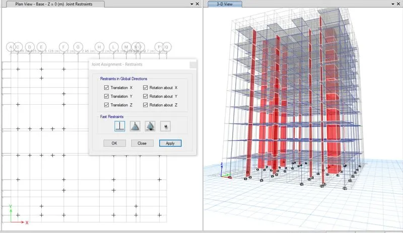
Define Restraints at base plan.
- At base plan select all the joints, next select the restraints at all the joints, as shown below.
Define the load patterns.
- After completing the model, now we need to list down the types of loads that are expected on the structure during its service period.
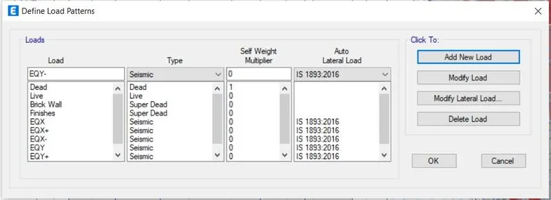
- Go to define > load patterns > add loads.
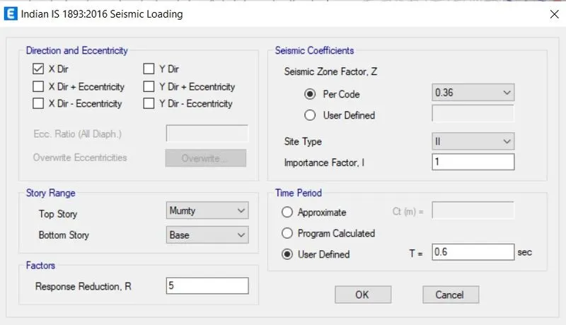
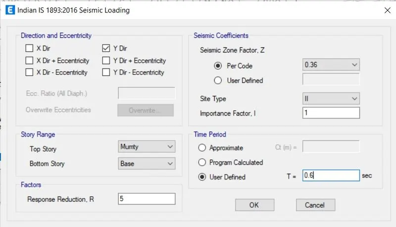
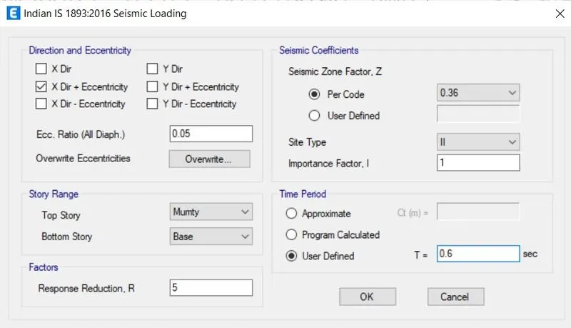
- Here, you can add all the loads and for our project, we are having the dead load, super dead load (Brick wall load), live load & the earthquake load in x & y directions.
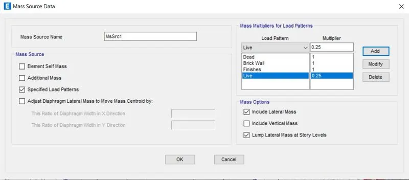
- Also, you need to define the mass source by adding 100% of dead & super dead load as well as 25% of the imposed or live load.
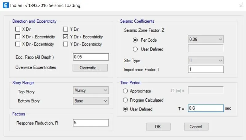
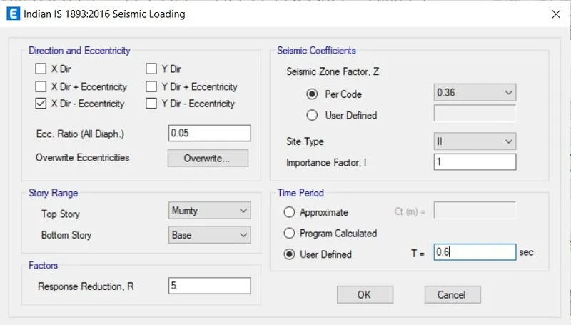
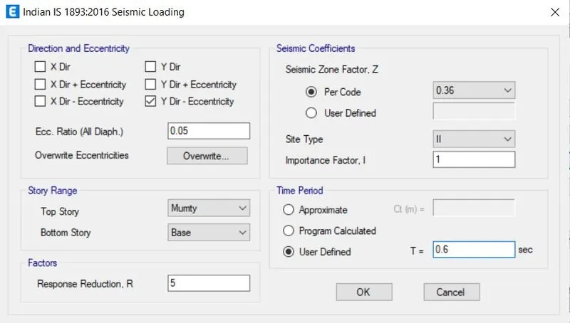
Check load cases:
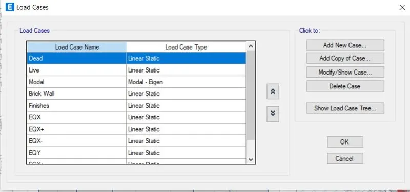
Mass Source Data:
Generate load combinations.
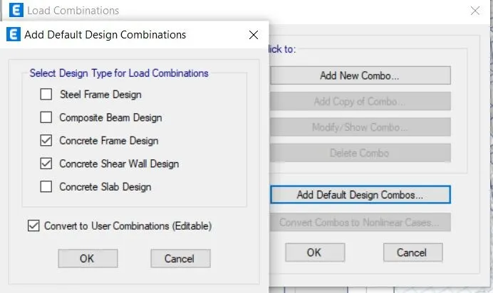
- Go to define > load combinations > check the convertible option.
- A list of load combinations will appear which you can look at and modify anytime during the project if needed.
Assign loads to the structural members.
- You can select a particular structural member from the model and assign it the load that is imposed on it.
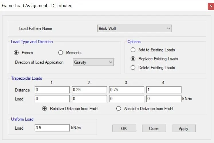
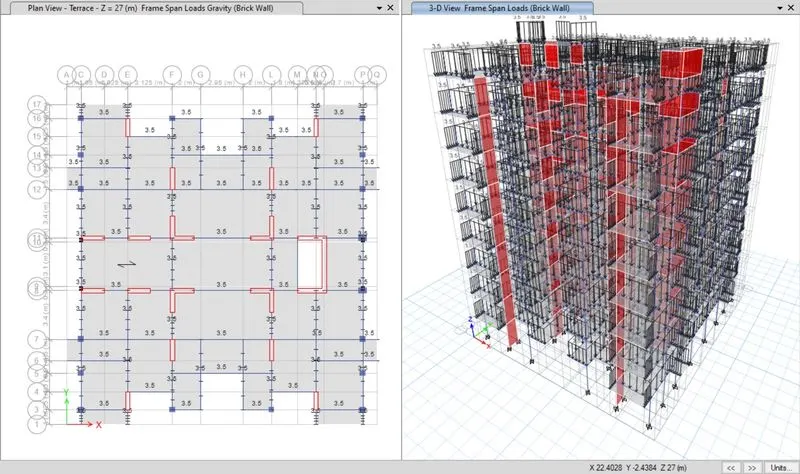
- For example, select the beam and assign a UDL of super dead load due to the brick wall resting upon it.
- Go to define > load combinations > check the convertible option.
- A list of load combinations will appear which you can look at and modify anytime during the project if needed.
3.5 KN/m brick wall load on beams
- Brickwall made of AAC blocks.
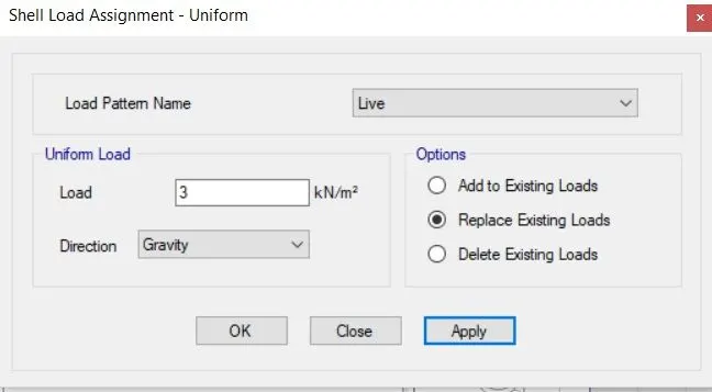
3 KN/m² Live load on Corridor, Balcony & Stair case area.
- Live loads as per IS 875 part 2
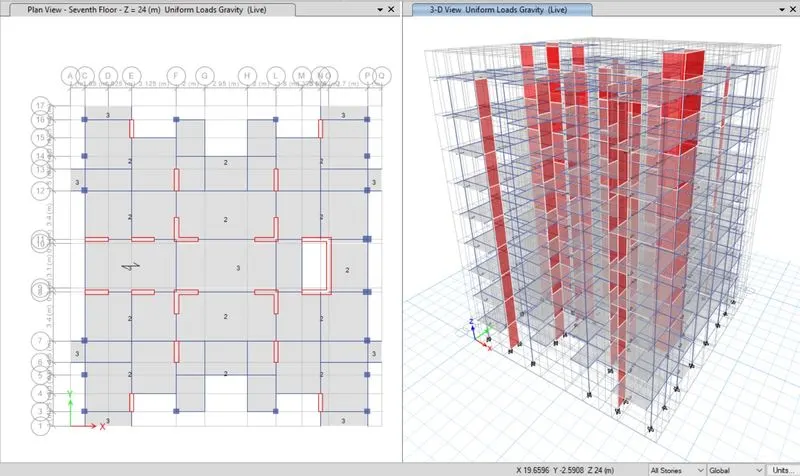
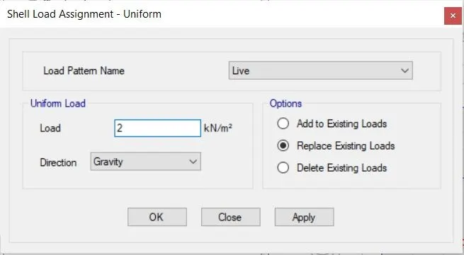
2 KN/m² Live load on Floor slabs.
- Live loads as per IS 875 part 2
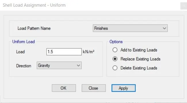
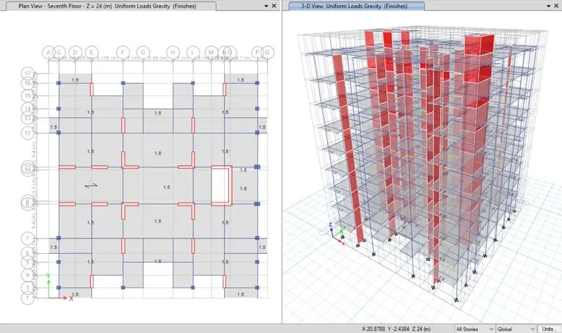
1.5 KN/m² Finishes on all Floor slabs.
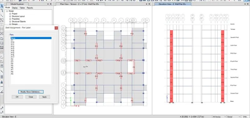
Shell assignment-Pier Label on Shell walls.
- Assign >frame >pier label.
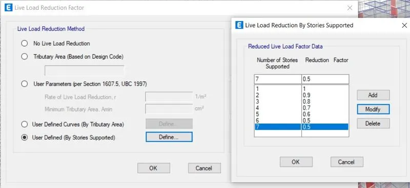
Live load Reduction 10%.
- Now we add the reduction factor by decreasing 10% from first floor to seventh floor, as shown below.as per IS 875 part 2
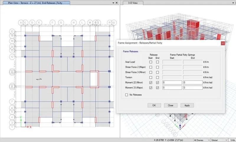
Frame assignment- Releases/partial fixity.
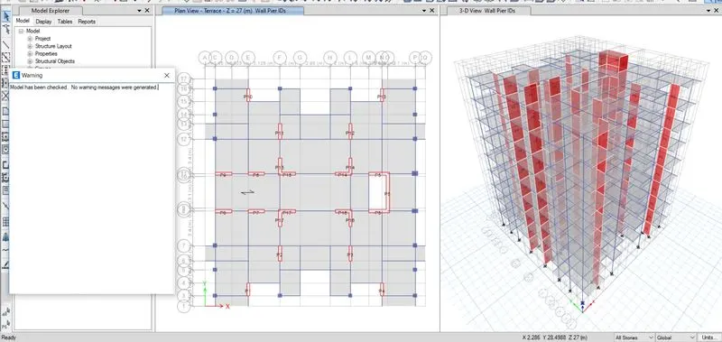
Check the Model.
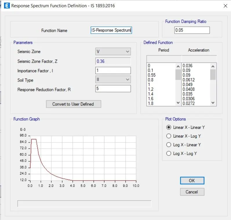
Function of Response Spectrum.
- Now, we select the response spectrum from define > function > response spectrum.
- After selecting the RS the new tab is visible,in that we choose IS 1893-2016, ''choose function type'' & click on modify/show spectrum option, as shown below.
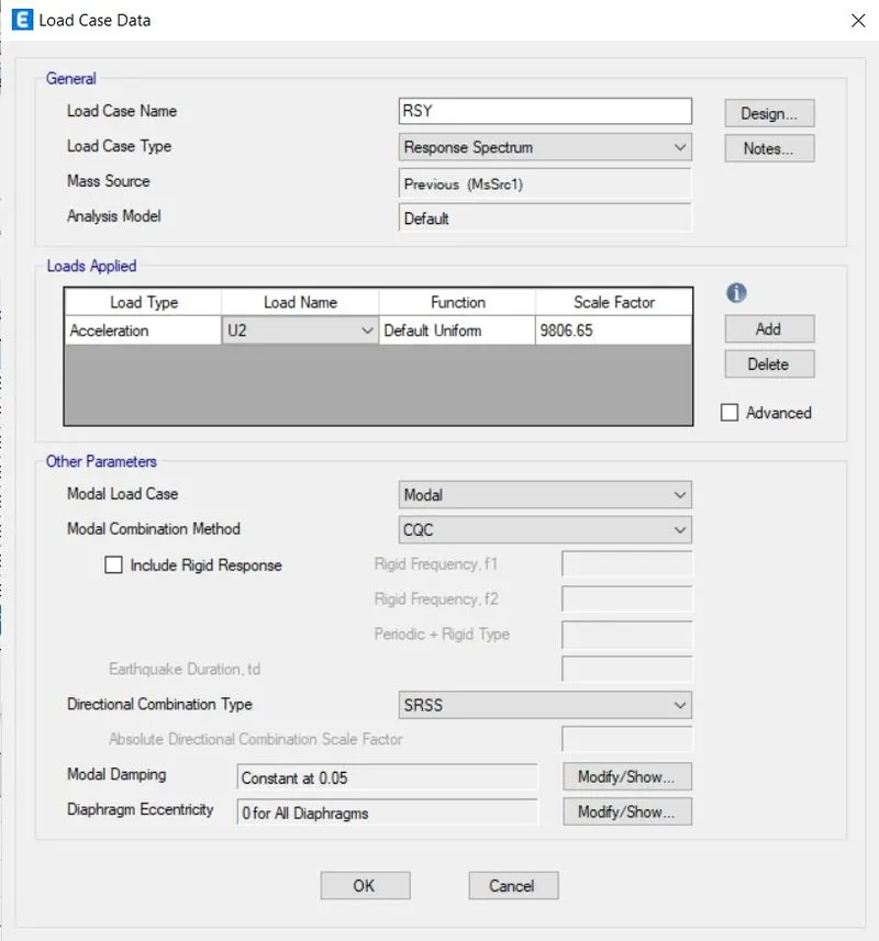
Load case data in Response Spectrum.
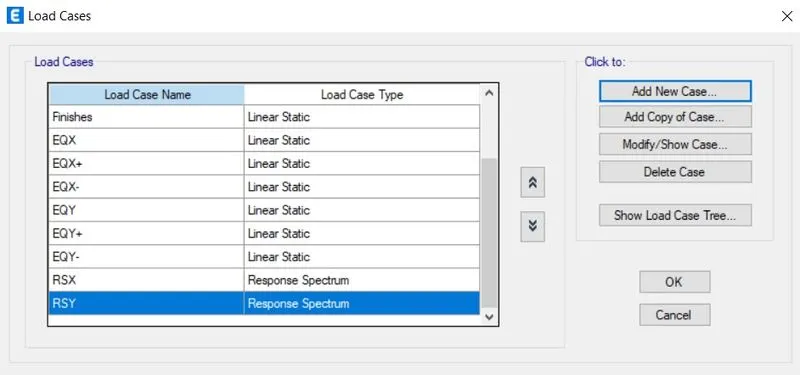
- In x-direction RSx, as shown below.
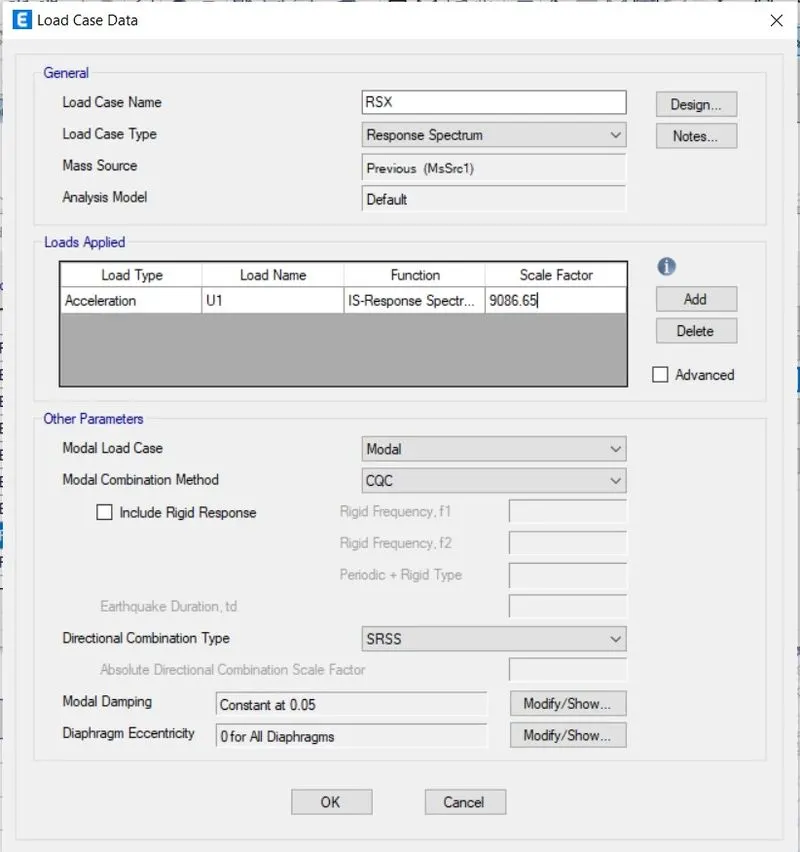
- In x-direction RSy, as shown below.
Assign the floor diaphragm
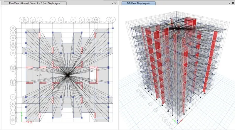
- Select the Slab150 slab section from the select option.
- Go to assign > shell > diaphragm.
- Select the default D1 diaphragm already incorporated in ETABS and press ok.
- It is now done, and you can see the center of mass for our model has been automatically calculated as we assigned the floor diaphragm.
Save the Model and Run Analysis.
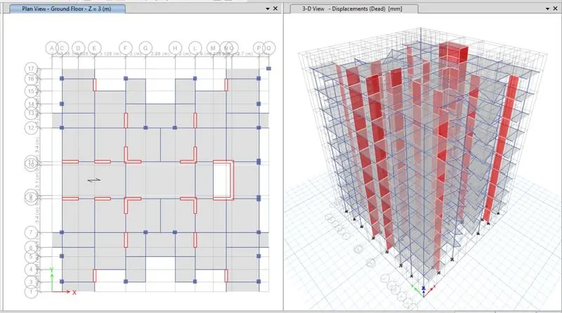
- Now that everything with regards to our first model is complete, we can proceed to run the analysis for this building.
- But we’ll have to first save our project before running the analysis so do it at the preferred location within your system.
- Then, you can simply press F5 on your keyboard or click on the arrowhead available on the ETABS screen to run the analysis for the current model.
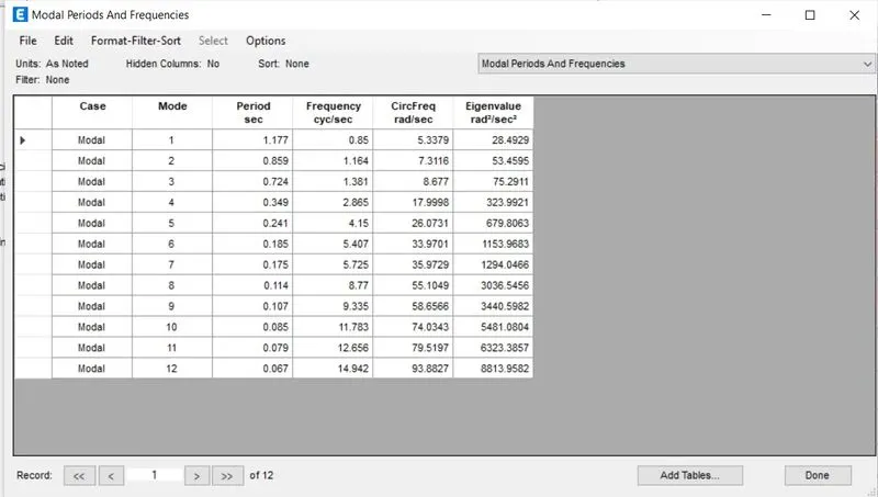
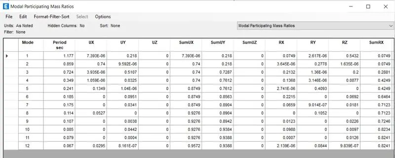
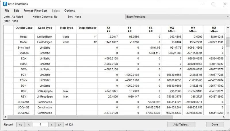
Modal Response for G+7 Building.
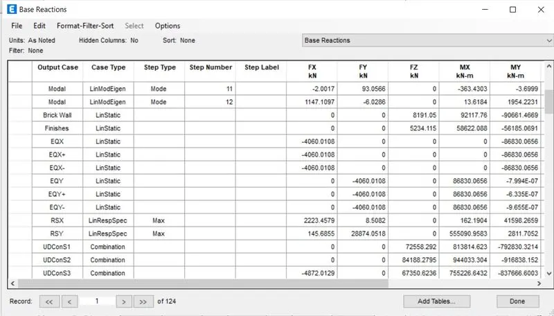
- Base reactions table as shown above.
- Here we have to check that EQ should be closer to RS to get the closer to each other, we should calculate that, (EQ / RS)x scale factor of RS.
- Now substituting the values from the table, as x-direction (4060 / 2230)x(9806.65), at y-direction (4060 / 28880)x (9806.65) from the above table..
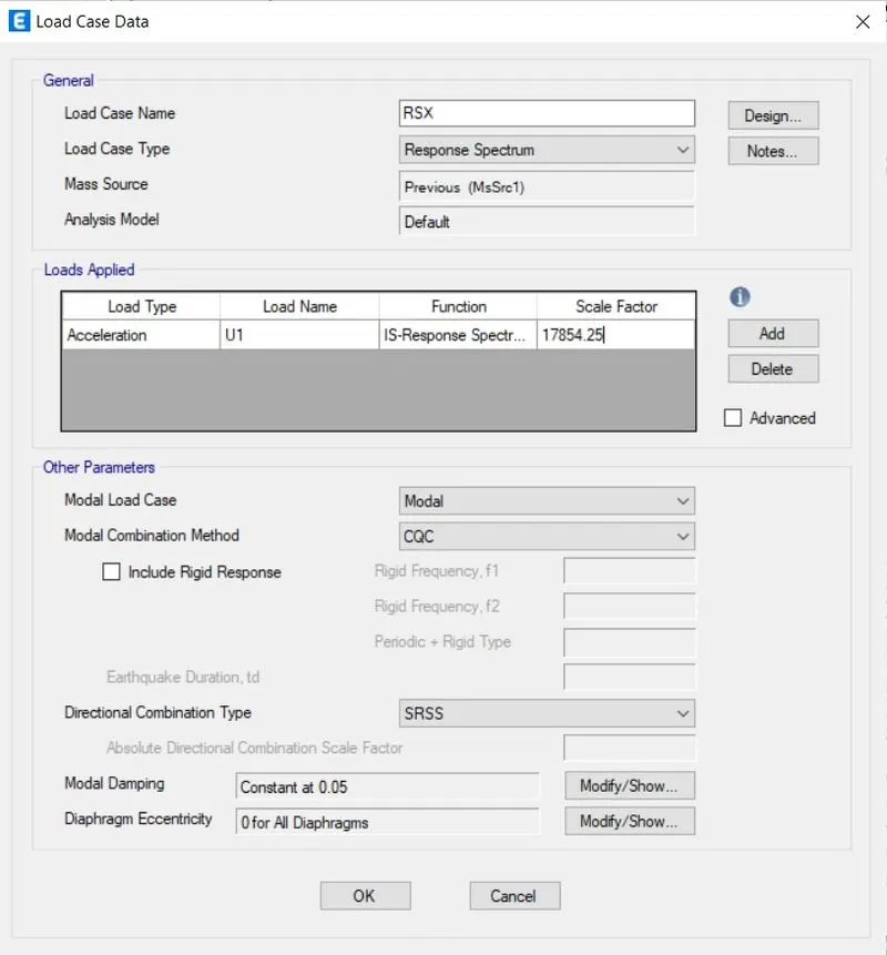
- At x-direction we get, 17854.25
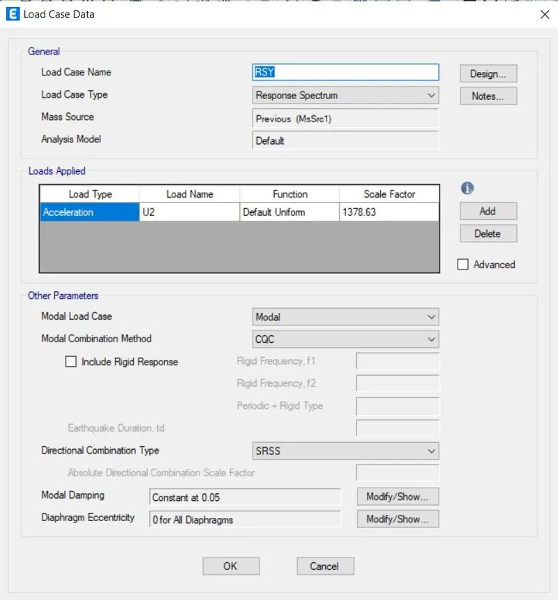
- At y-direction we get, 1378.63
- we put the above values as scale factor for RS at x & y-directions in the load case data, as shown below.
Load case data in Response Spectrum.
- In x-direction RSx, as shown below.
- In y-direction RSy, as shown below.
Modal Response for G+7 Building.we get.
- After we enter these for response spectrum as scale factors at x & y-directions in load case data, then the EQ is closer to the RS from the base reaction table,as shown below.
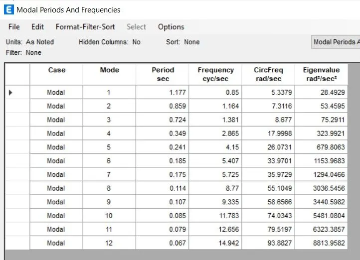
The shown Principal modes to be greater than torsional mode
Therefore, modal 1 & 2 is greater than modal 3.
Hence Achieved.
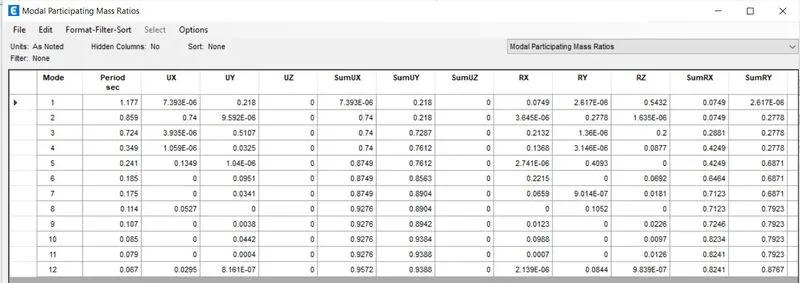
Modal mass ratio in x-direction 0.74 + 0.149 = 0.889.
Hence 65% is achieved in x-direction.
- Next we open the select plan view tab and select the base floor.
- Nect we have to open reaction tab, then we select the earthquake load towards y-direction(EQy) in the load case, then click on the ok button, as shown below.
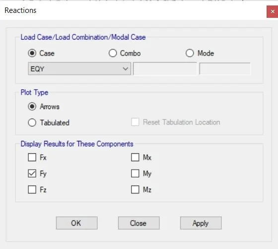
- Now the base shear reaction will appear, as shown below.
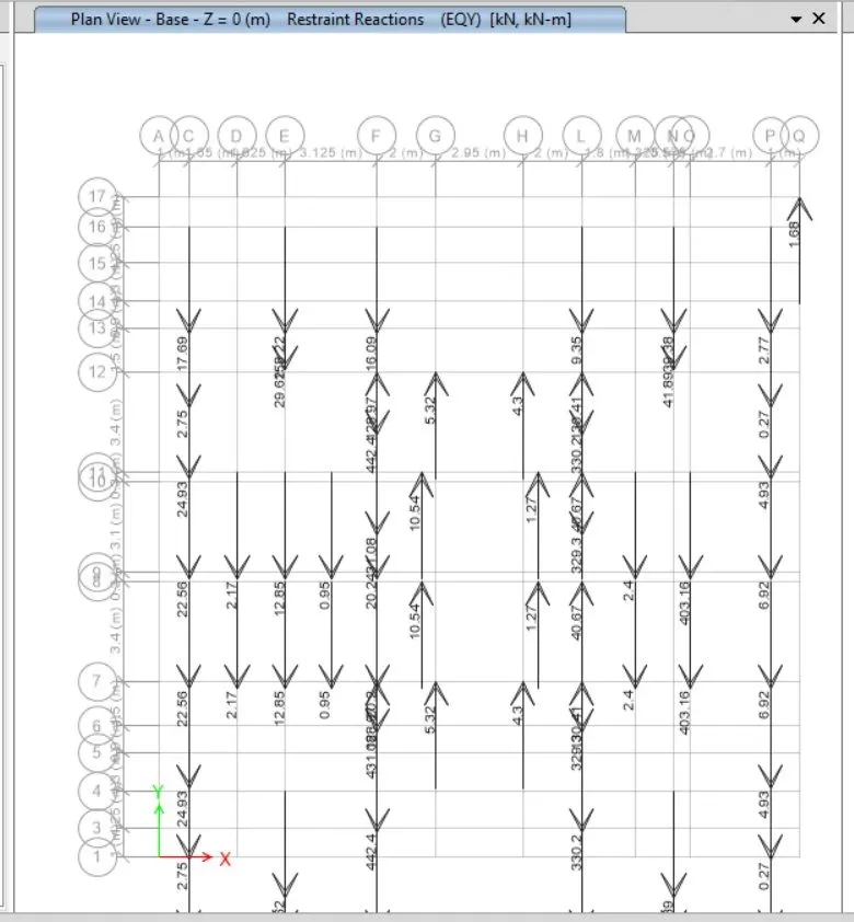
Base reaction values in y-direction(EQy) as shown below.
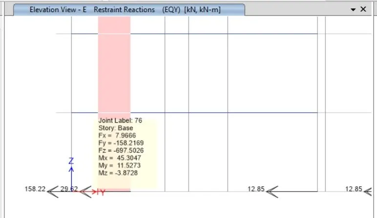
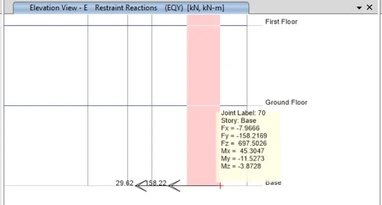
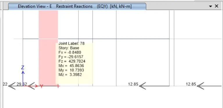
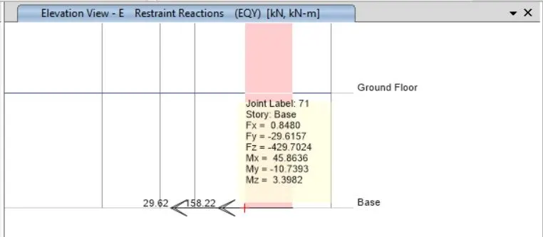
- When we divide the base shear taken up by the shear wall divided by the total base shear of building will get the % of the shear forces taken up by the shear wall.
- And, if that is less than 80% then the more shear wall we need to add to the structure.
- = (158 +158 -429 -429 )
- = 542 x 8(no:of shear walls in y-direction) =4336
- = 4336 / 4060(base reaction) =1.06 = 100 %
Axial load ratio of columns within 0.4.
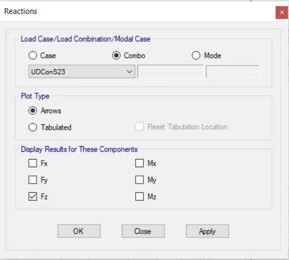
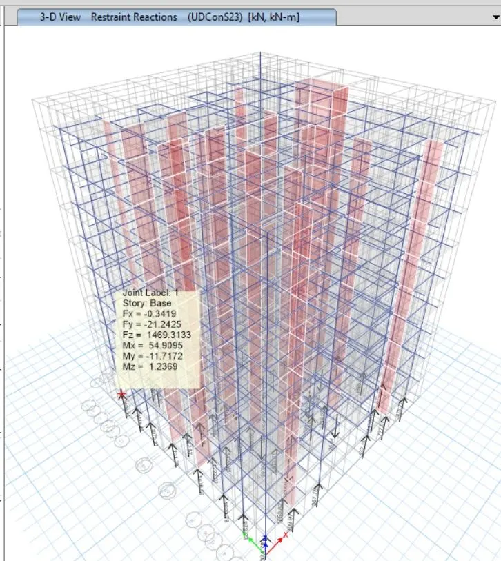
- Maximum load reaction is noted in Fz direction, as shown above.
- caluculate, if the column load ratio lies within 0.4
- = 1469 KN x 1000 = 1469000 N
- = 1469000/(c.s of column)/concrete grade
- = 1469000/400/400/25 =0.36.
- Hence, OK.
Maximum storey drift ratio EQx & EQy.
- Display > storey response plots.
- In display type > check max storey drifts
- In case/combo> check EQx & EQy, as shown below.
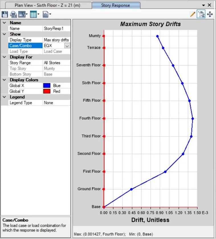
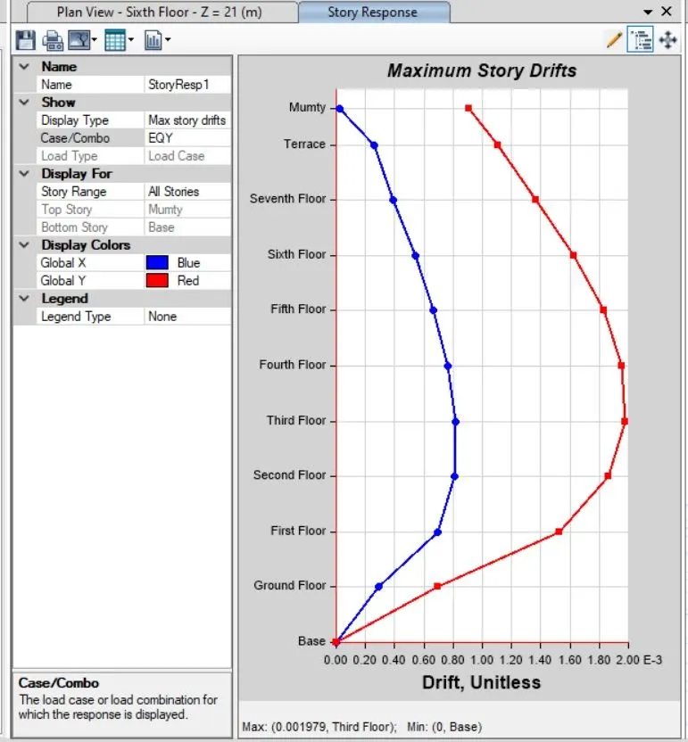
- As we can check in EQx, maximum storey drifts is 0.0014.
- As we can check in EQy, maximum storey drifts is 0.0019.
- Hence inter storey drifts ratio is limited wthin 0.004.
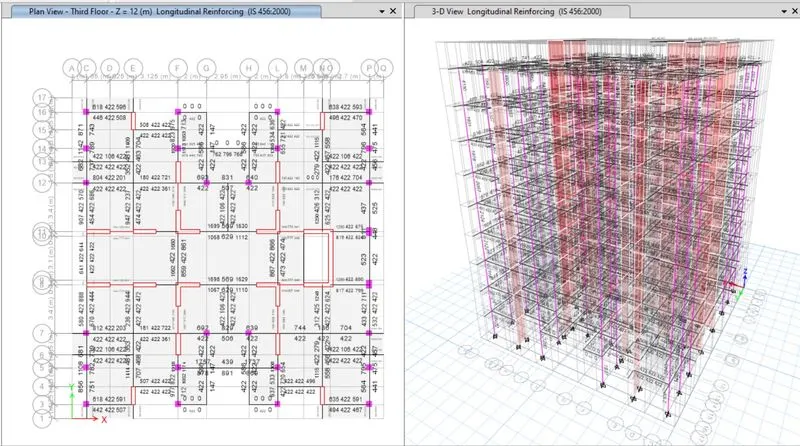
Concrete Frame Design.
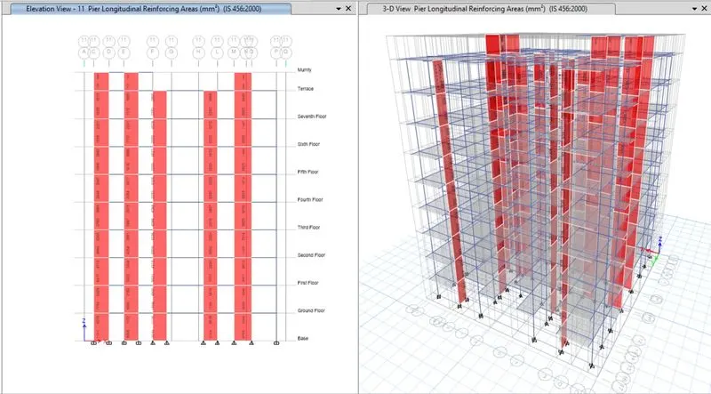
Shear wall Design.
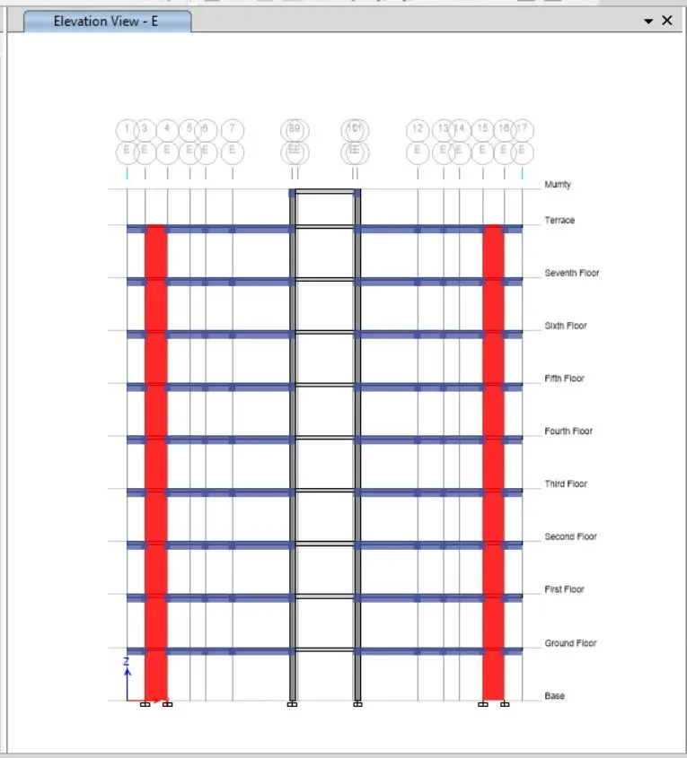
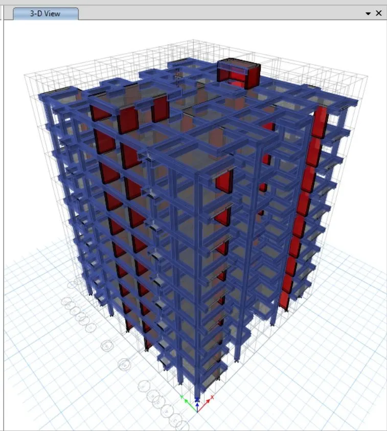
Extruded Residential building Typical Floor plan, Elevation and 3D view
Typical Floor plan View.
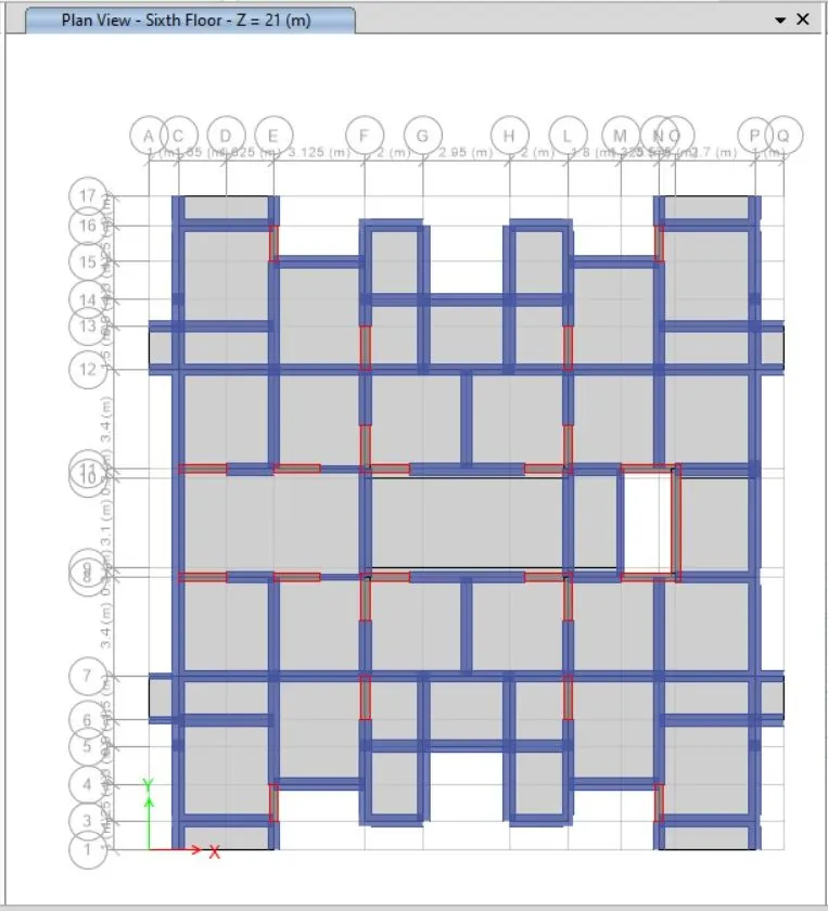
Elevation View.
3D View.
RESULT:
- Modal mass ratio in x-direction is 0.889,Hence 65% it is achieved.
-
The Principal modes to be greater than torsional mode,modal 1 & 2 is greater than modal 3,Hence Achieved.
- Maximum storey drifts ratio in EQx=0.0014, EQy=0.0019,it is limited wthin 0.004,Hence Achieved.
- Axial load ratio of columns is 0.36,it is limited within 0.4, Hence Achieved.
- Base shear reaction is 1.06, it should not be less than 80%, Hence Achieved.
- Response spectrum, the EQ is closer to the RS from the base reaction table as shown 4060 KN,Hence OK.
- The Residential building with all seismic considerations,has been modelled and analyzed based on given architectural inputs using ETABS is successfully completed.