Structural Modelling using Etabs 2018
AIM: model and analyze the G+7 residential building from the given architectural drawing using the ETABS 2018.
INTRODUCTION:-
- Modellings tools and templates, code-based load prescriptions, analysis ethods and solution techniques, all coordinate with the grid-like geometry unique to this class of strucutre.
- Basic or advanced systems under static or dynnamic conditions may be evaluated using ETABS
- ETABS modelling is the generlization that multi-story building typically consist of identical or similar floor plans that repeat in the vertical direction.
- Modelling features that streamline analytical-model generation, and simulate advanced seismic systems.
- Once modeling is complete , ETABS automatically generates and assigns code-based loading conditions for gravity, seismic , wind and thermal forces.
PROCEDURE:-
- Check the architucre plan of given attach and create grids & supports
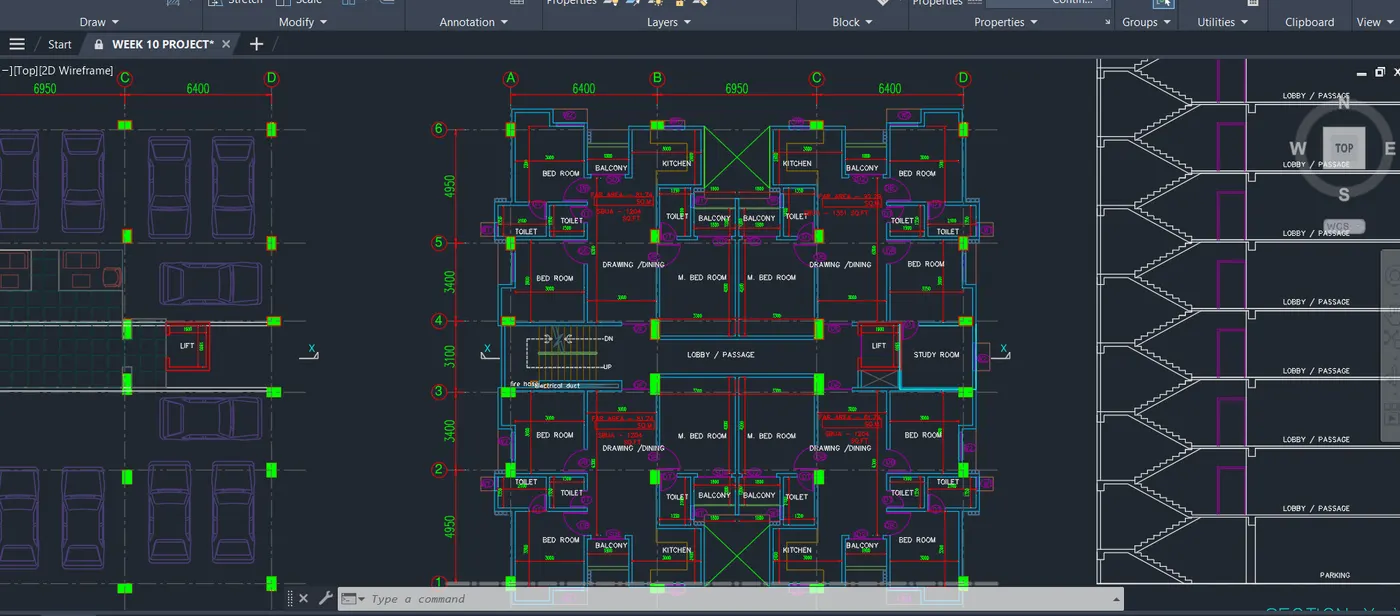
- First we have to open the ETABS software.
- Next click on the file option at the left side top corner and select the new model, as shown below.
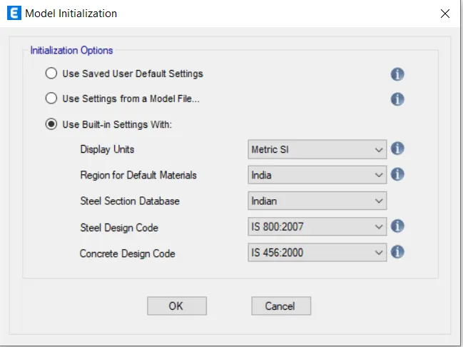
- After selecting the new model the new tab opens, in that tab we have to select USe Built- in settings with option as shown below.
- Next we need to do the settings in Grids system data, as shown below.
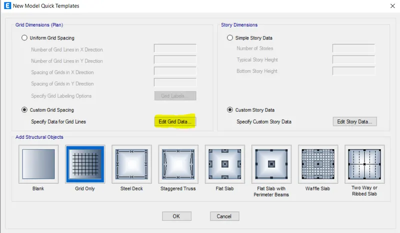
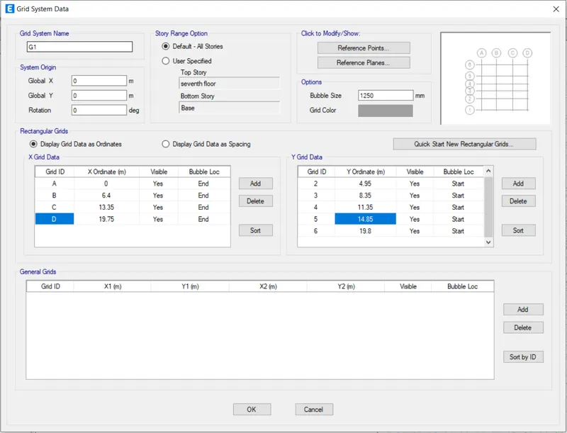
- The above given data is according to the architectural file that have been provide to us story data also.
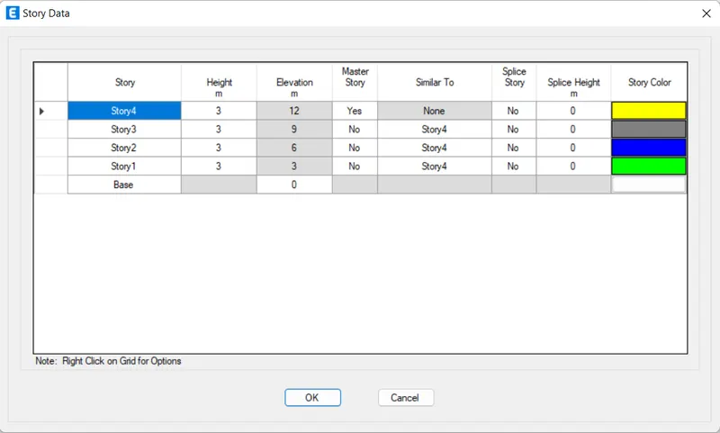
- So in order to do so just click on the Custom story Data and then click on the option edit stroy Data just as shown in the below given image:
- After clicking the edit story Data option there will be another dialouge box named as the edit story Data, and we need to add the stories upto the 7 floors so just add the stories just as shown in the below image:
- Now fill the relevant data required just as shown in the below given image
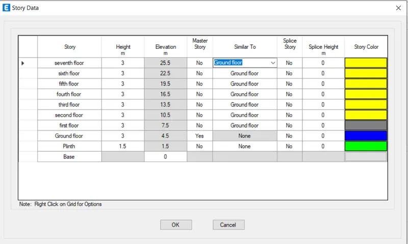
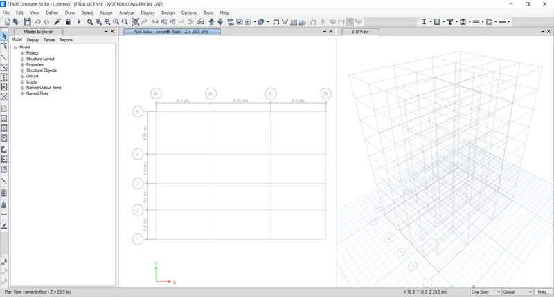
- The story and the grids setup have been completed.
- So the plan view and the 3D view has been shown below in the image:
- After setting the grids and the story data now we need to define the materials and the section properties as well.
- So in order to set the materials first we need to go to the define option and there will be a drop- down list in that list there is another option called matrial properties just as shown in the below given image
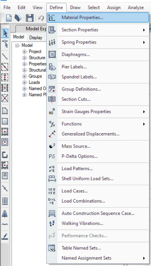
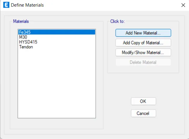
After clicking on the materials property there will be another dialouge box named as Define material, in that dialouge box just click on the option and new material just as shown in the below given image :
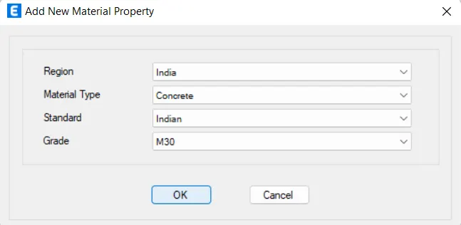
- After that there will be another dialouge box named as Add new material property fill the relevant data in that dialouge box just as shown in the below given image:
- Region : India
- Material Type : Concrete
- Standard :India
- Grade : M30
M30 Concrete ;
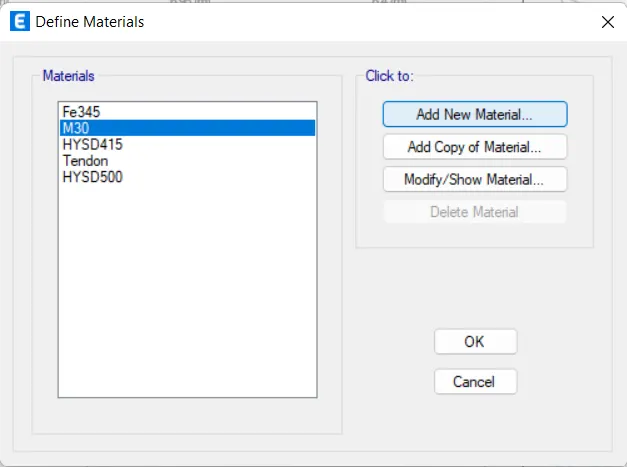
After adding the M30 concrete, now we will be adding the another material
And to do that we need to click on the Add new material option in the same dialouge box just as shown in the below given images.
- Now we will have to define the frame properties. We will be adding the columns, slabs shear wall etc.
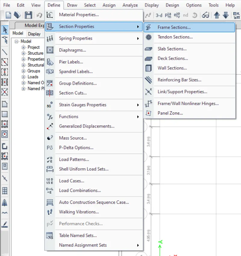
- So in order to do that first we need to go to the option Define tab there will be a drop-down list in that is another option called section properties and then click on the option Frame section, just click on that option just as shown in the below given image;
- After clicking on the Frame section option there will be a dialouge box named as Frame properties, click on the option Add New propety just as shown in the below given image;
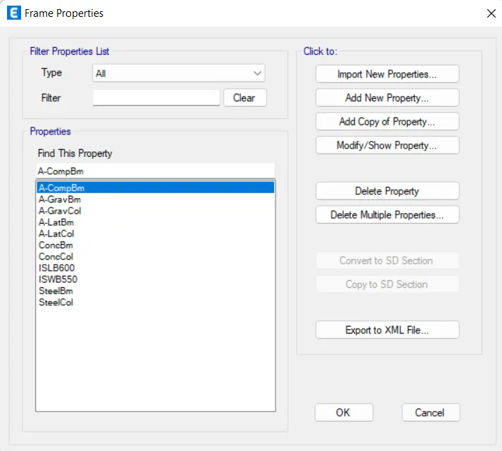
- First we will be adding column of size 450 x560, so in order to do that click on the option Add New property and after Dialouge box named as Frame property shape type in that dialouge box choose the section shape as concrete Regular and the concrete frequently used shape as rectangle and jus as shown in the below
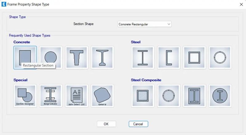
Column 400 x 600 mm:
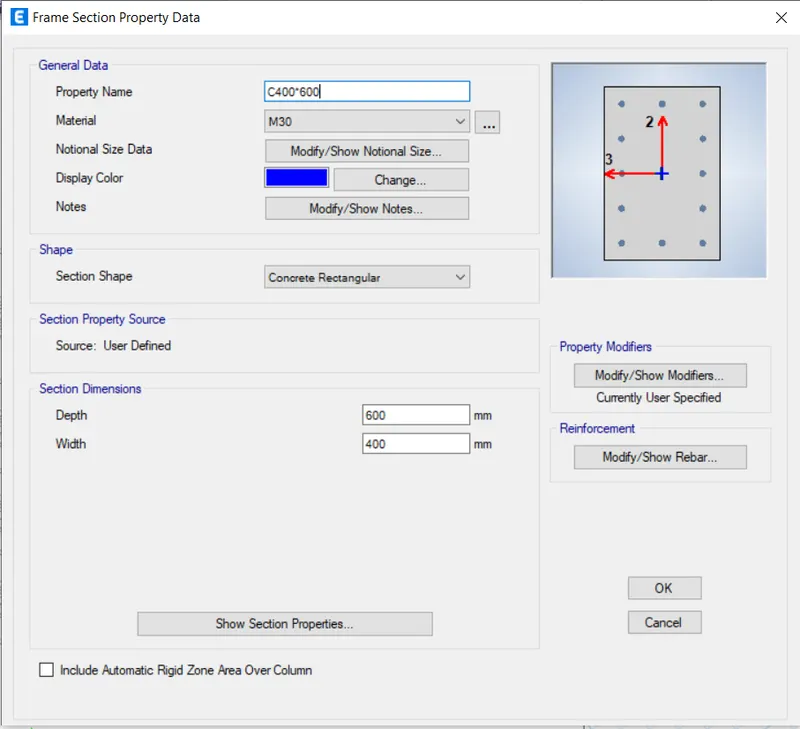
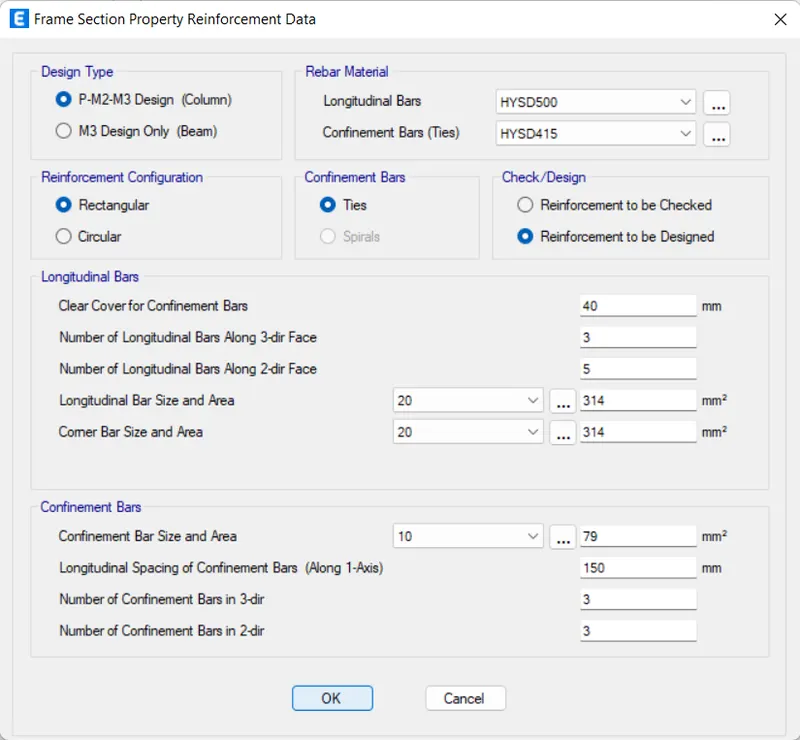
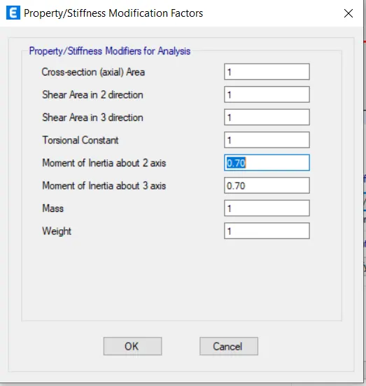
- The moment of inertia in case of the column about 2nd and 3rd axis was reduced to 0.70 just as shown in the below image;
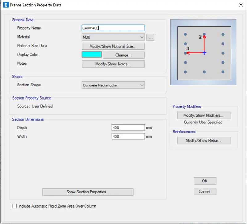
Column 400 x4000 mm:
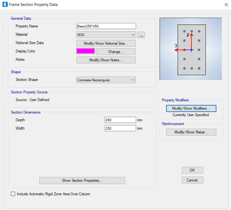
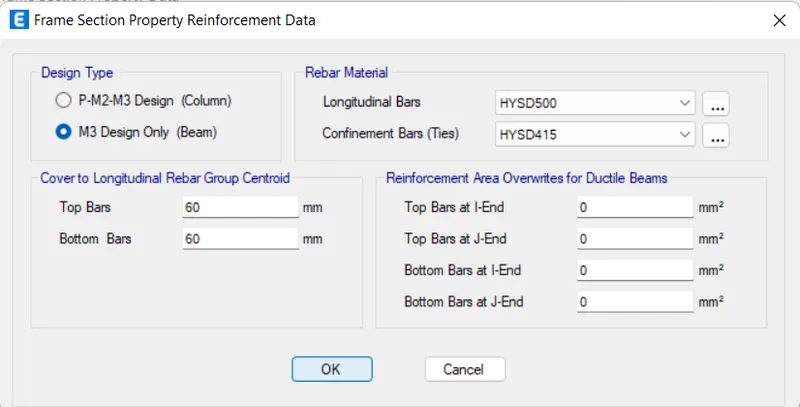
Beam 250X 450mm:
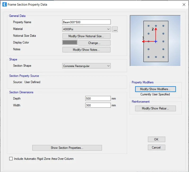
Beam 300 x500:
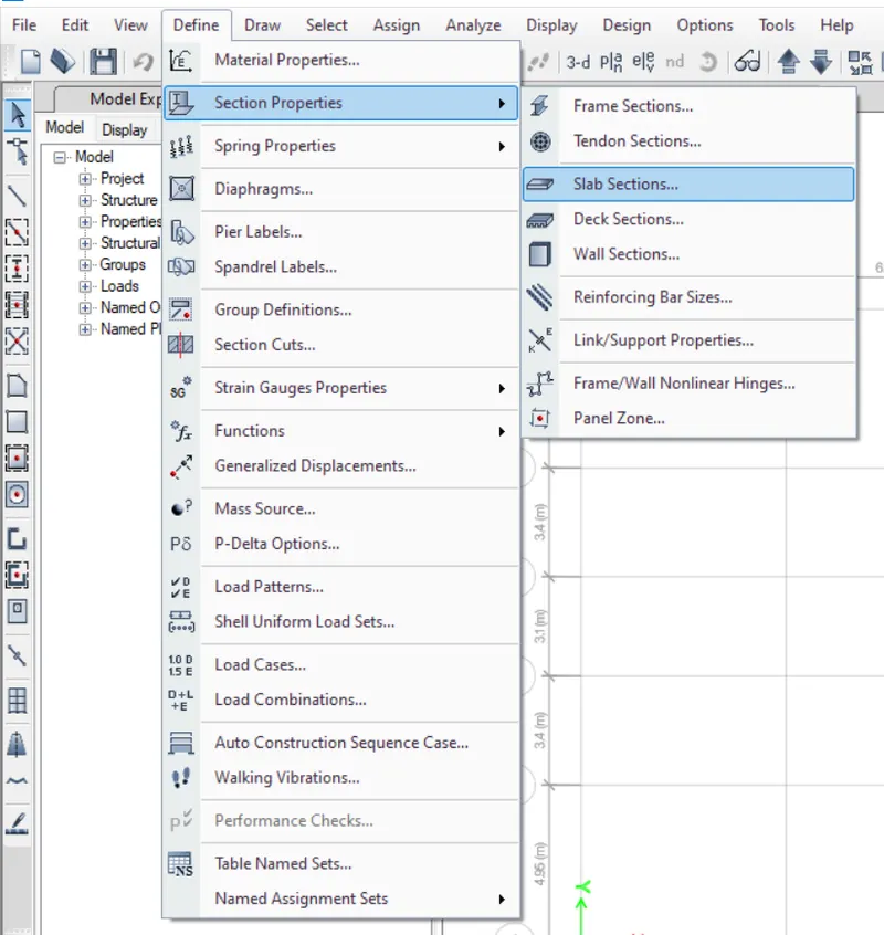
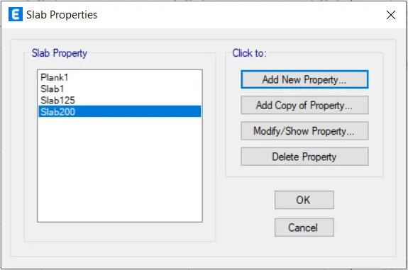
- Select the properties and another option called slab section just click on the option just as shown in the below given image:
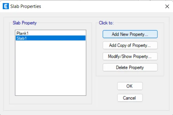
- Add new property just clicking on that option just as shown in the below image:
SLAB 125 mm:
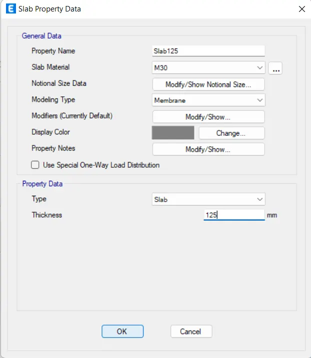
- And similary we will be adding the slab for the staircase of 200mm thickness.
- Do the same procedure as we had done for the slab 125mm.
SLAB 200mm:
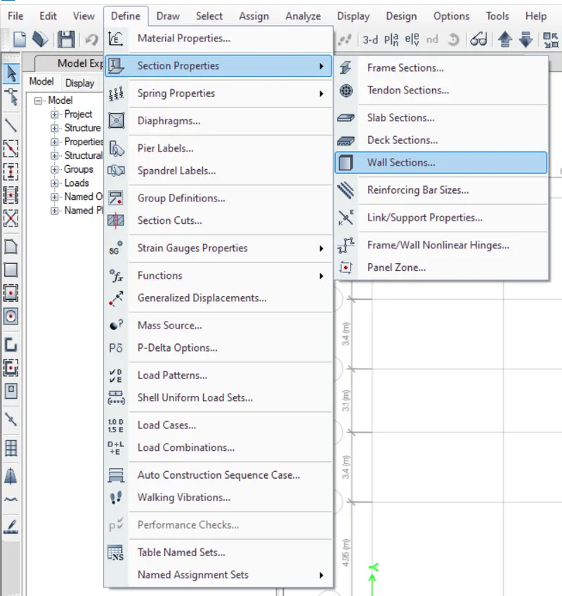
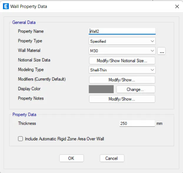
Wall proprties:
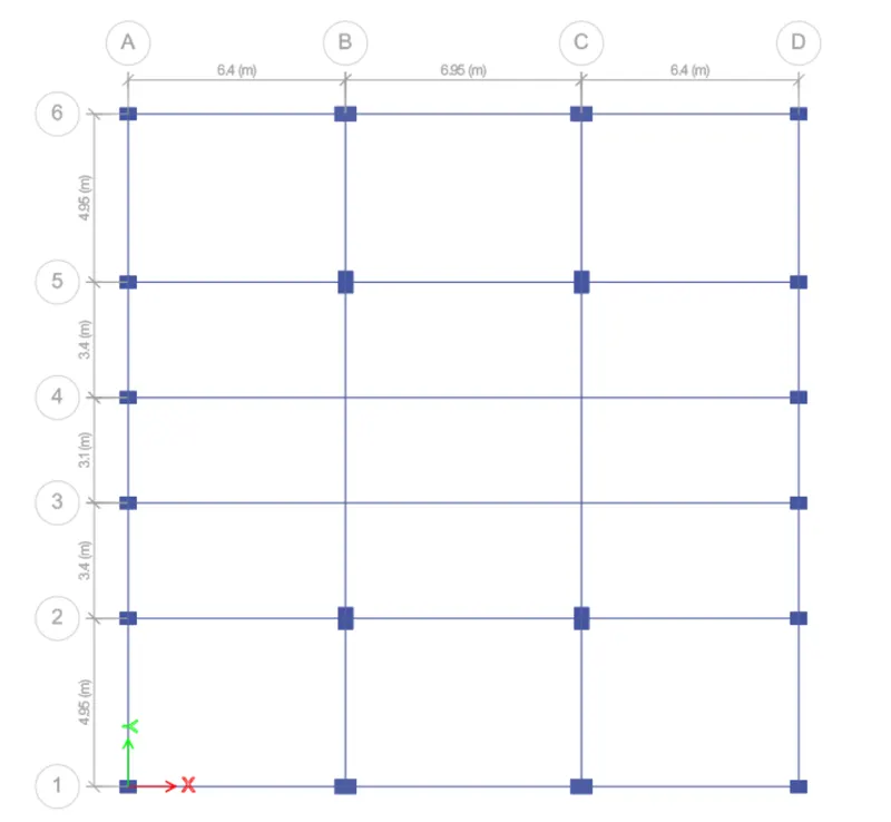
- Now place the column according to the given autocad file and the requirement of the question.
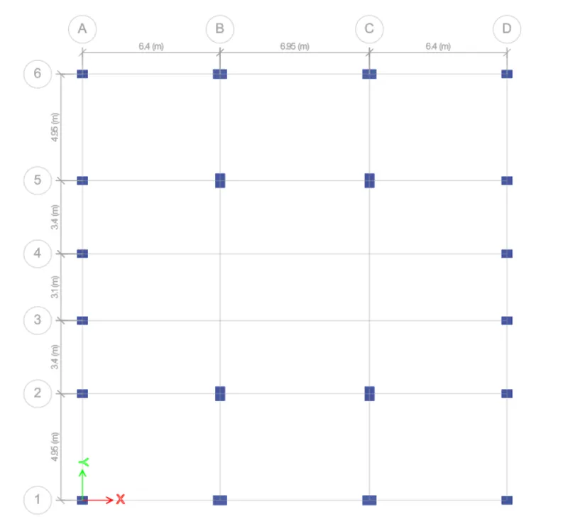
- Similar add the beams just as shown in the below given figure:
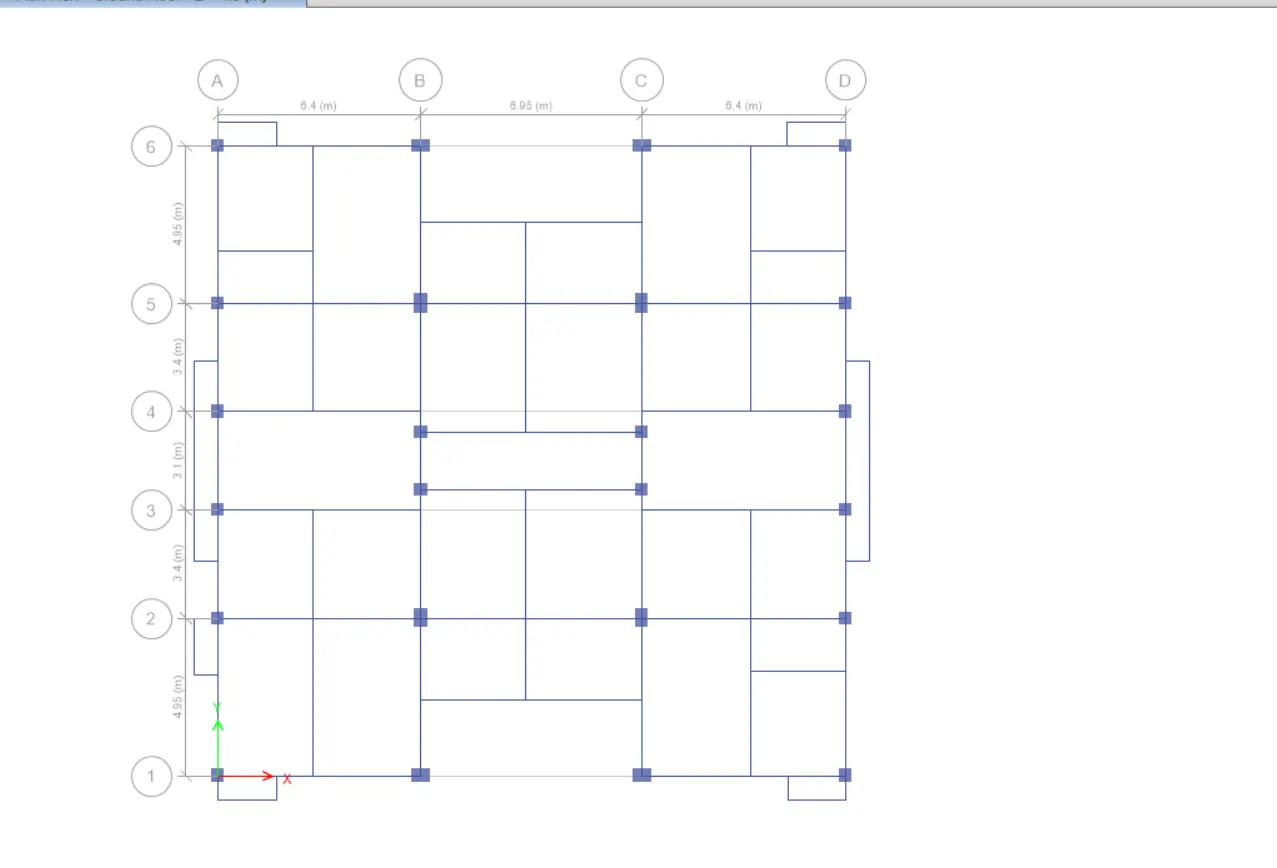
- Adding the secondary beam adding the balcony required:
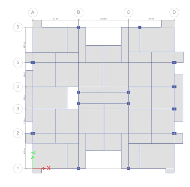
- Adding floors in model :
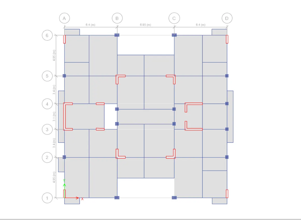
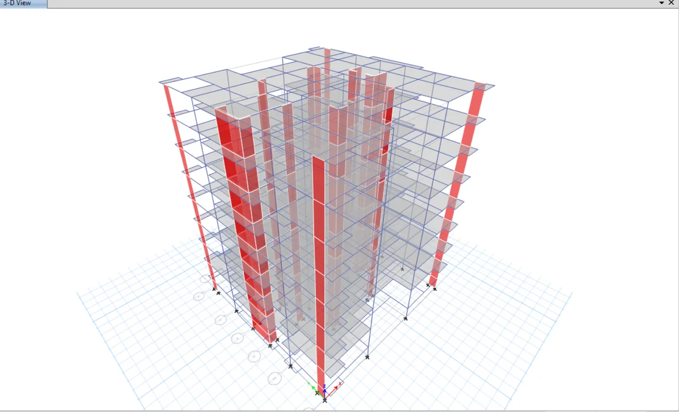
- Draw the shear walls wherever needed just as shown in the below given image:
- After assign all the properties like column, beam, slabs etc now we have to assign the load patterns.
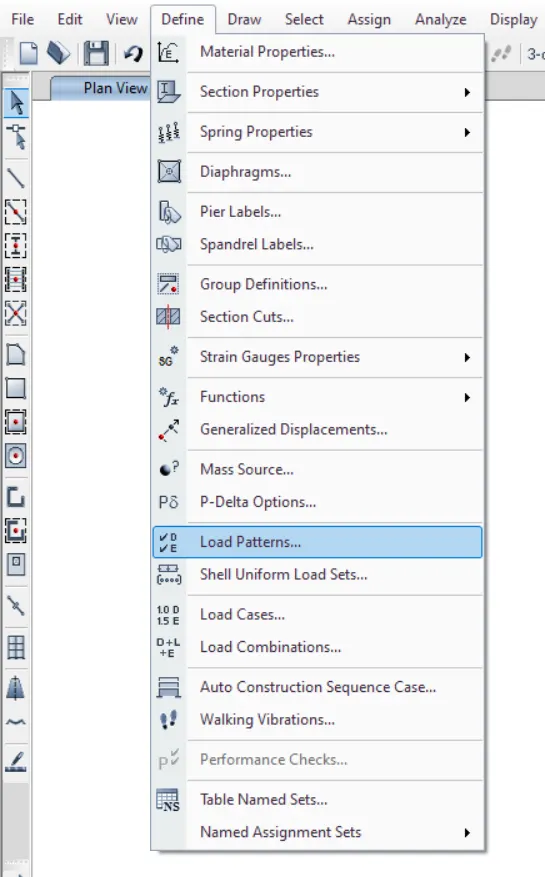
- In order to assign the lodas patterns first we need to go to the Deine tab then threr will be a drop-down list in there will be an option called load patterns just as shown in the below given image:
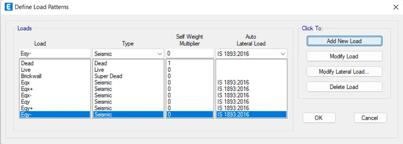
- After clicking on that option there will be a dialouge box opened named as Define Load patterns in that dialouge box assign all the loads Live load, Dead load, super dead loads and the seismic loads just as shown in the below given image.
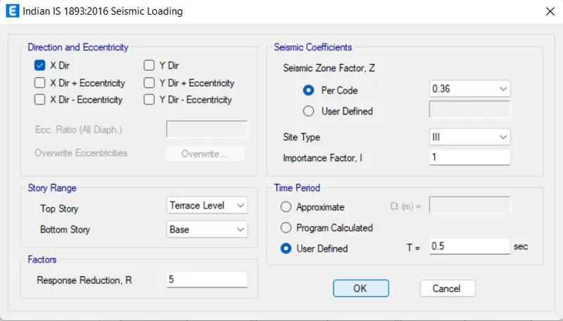
- The Response Reduction factor here take as 5.
- Seismic Zone is 5 so take the value of Z as 0.36
- Soil type is given as III.
- And the time period is taken as 0.5sec.
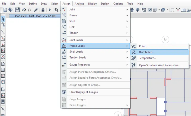
- Frame load assin then there will be a drop down list there will be a drop down list in that list there is an option called Distributed just as shown in the below
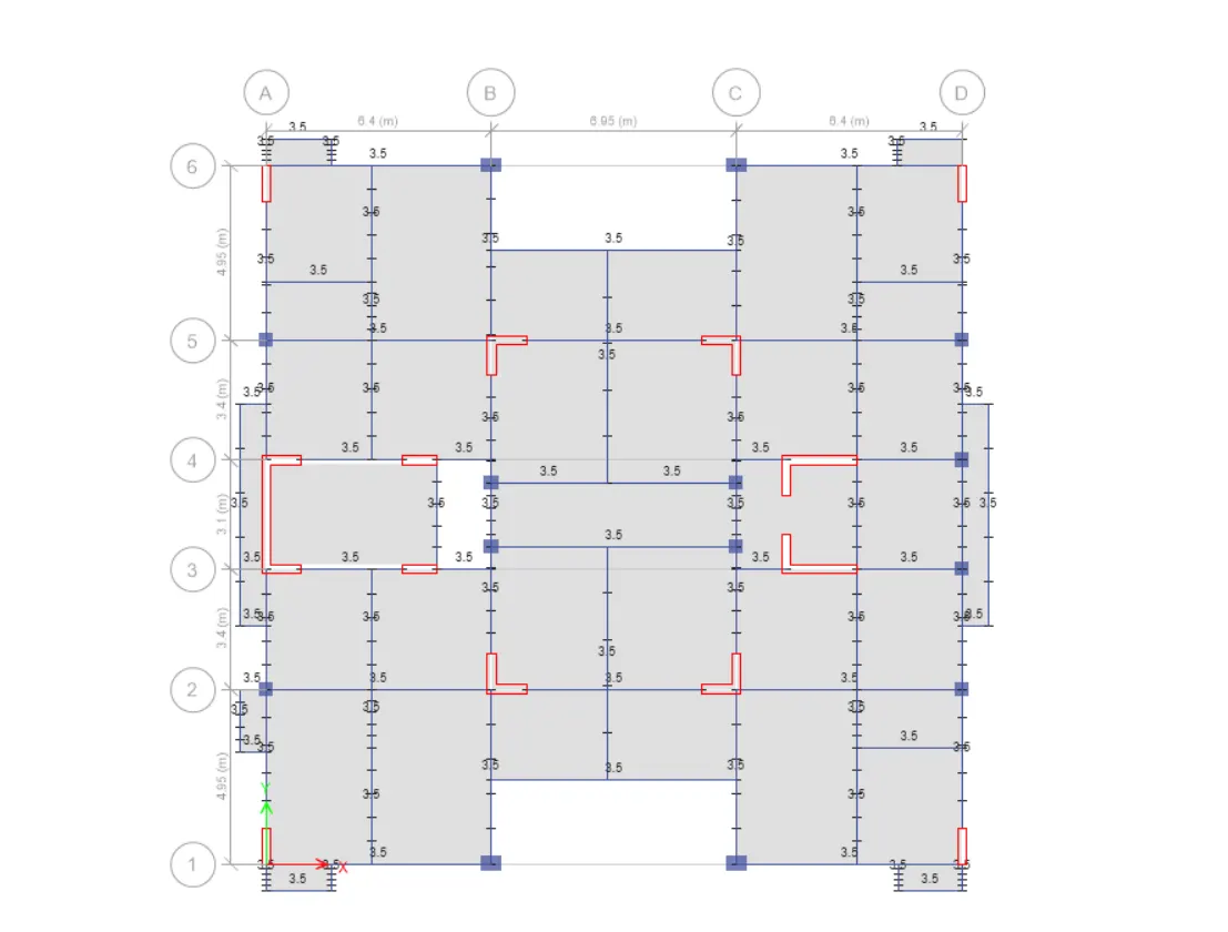
BRICK WALL LOAD:-3.5KN/m:
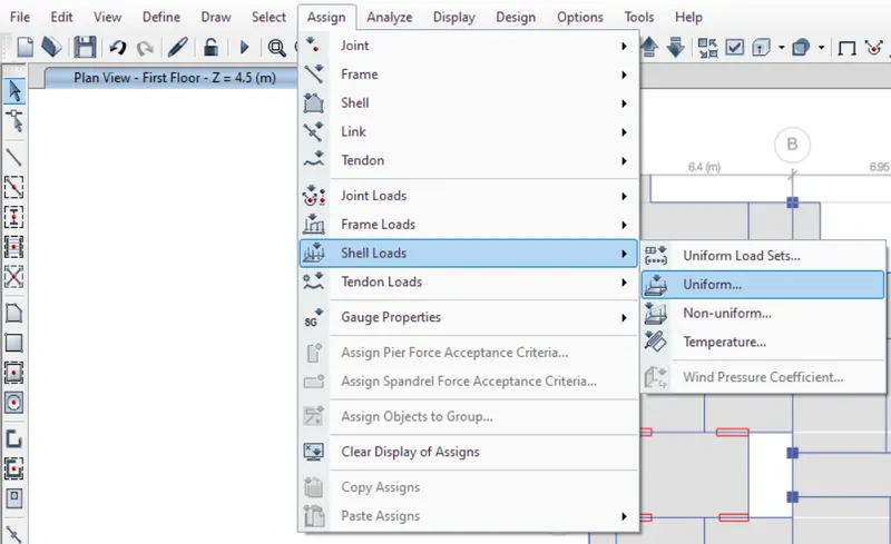
- After applying the dead loads to the structure now we will be applying the live load.
- So in order to apply the dead load first we need to go the option Assign and then there will be a drop
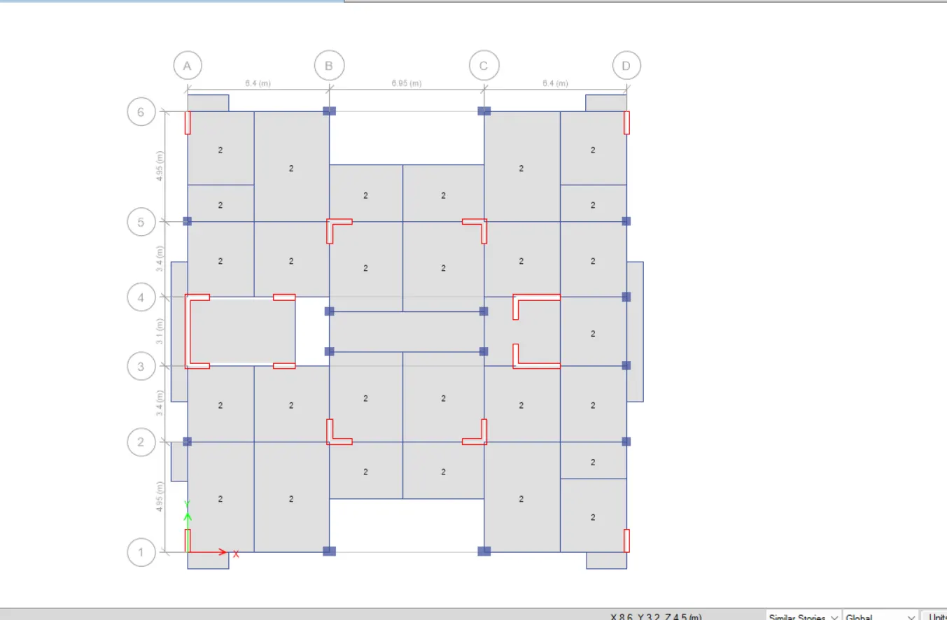
For Rooms: 2KN/ sq.m
For Bathrooms, staircase lift : 3KN
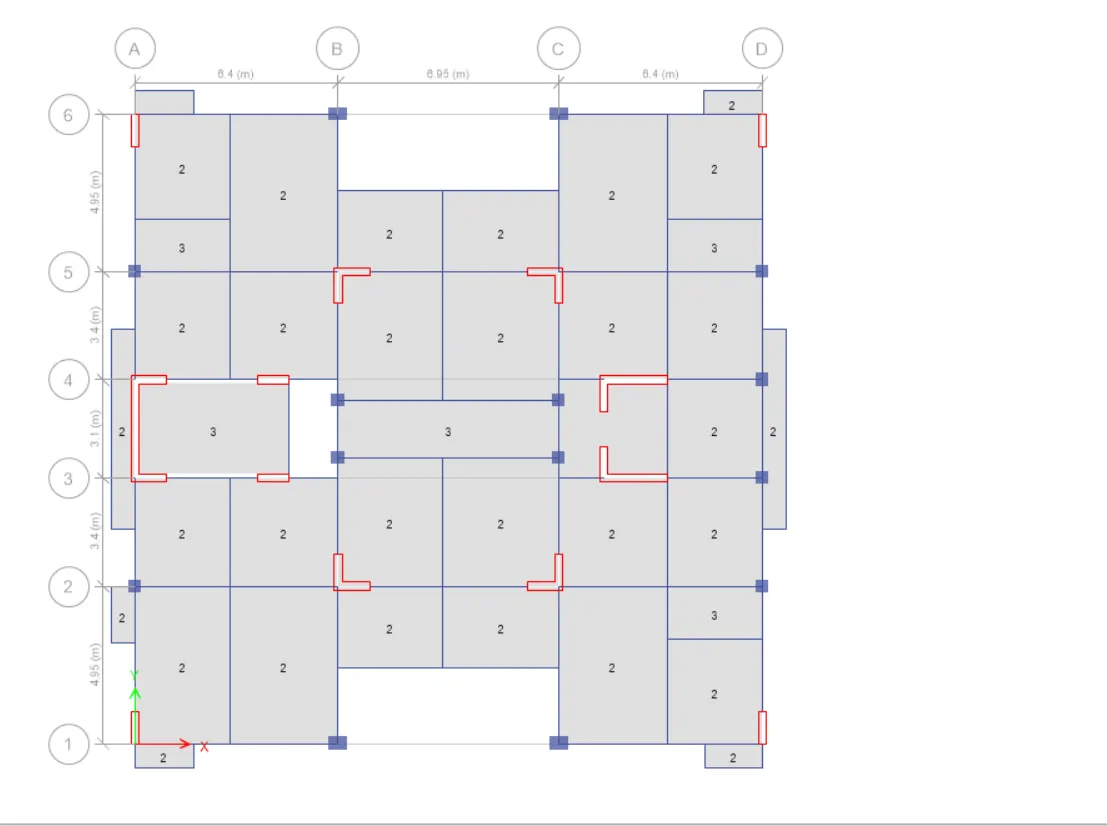
Floor Finishes:
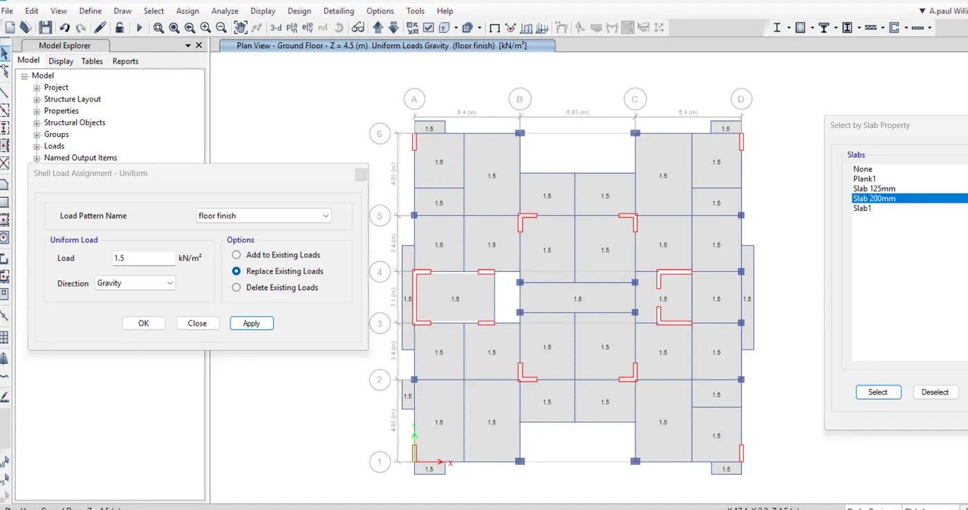
- Live load reduction factor , in that dialouge box there will e an option called user defined just click on that option just as shown
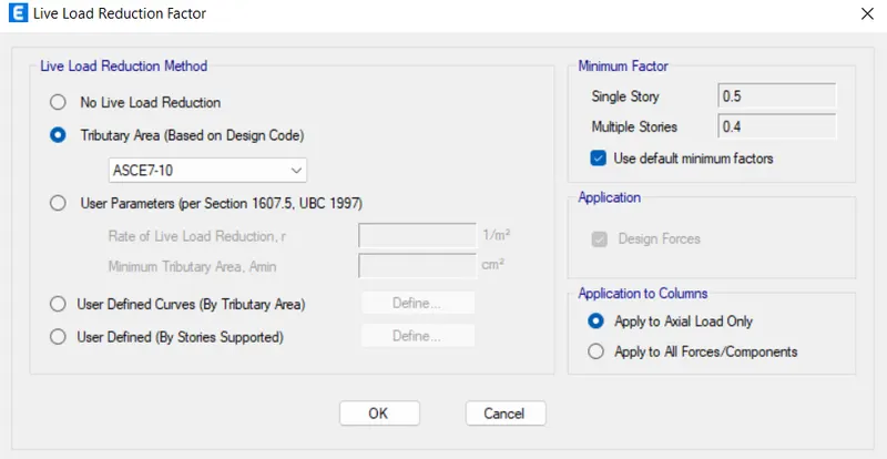
Mass Source:
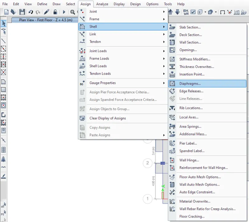
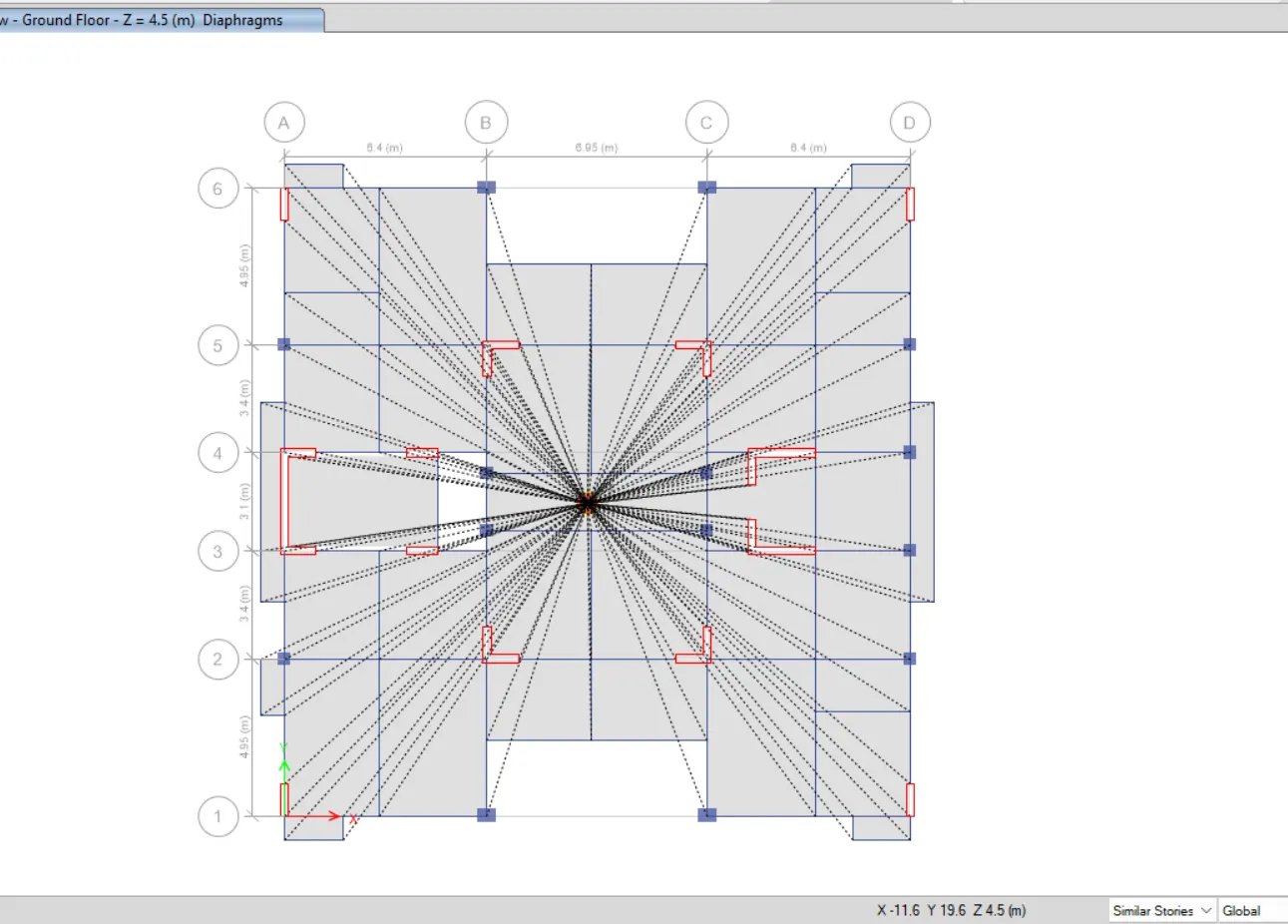
Diaphragm:
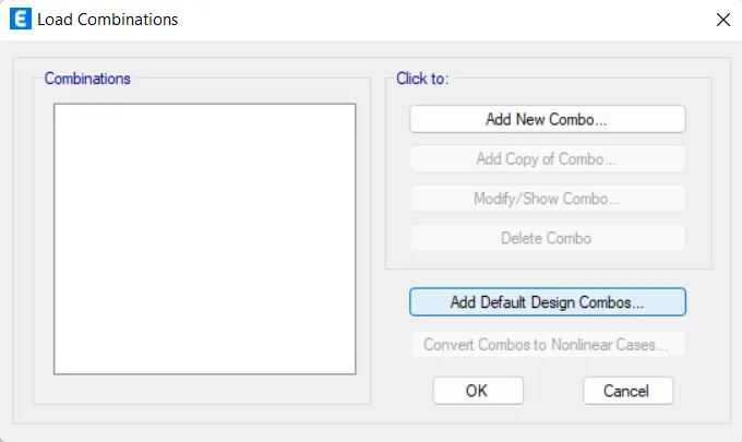
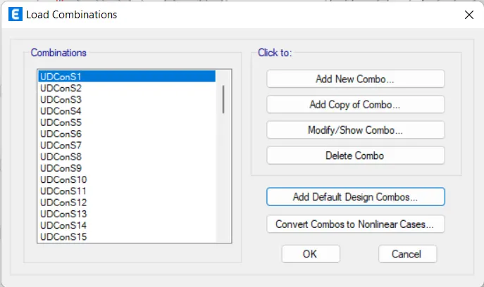
- Load Combinations
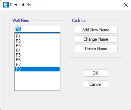
Pire labels:
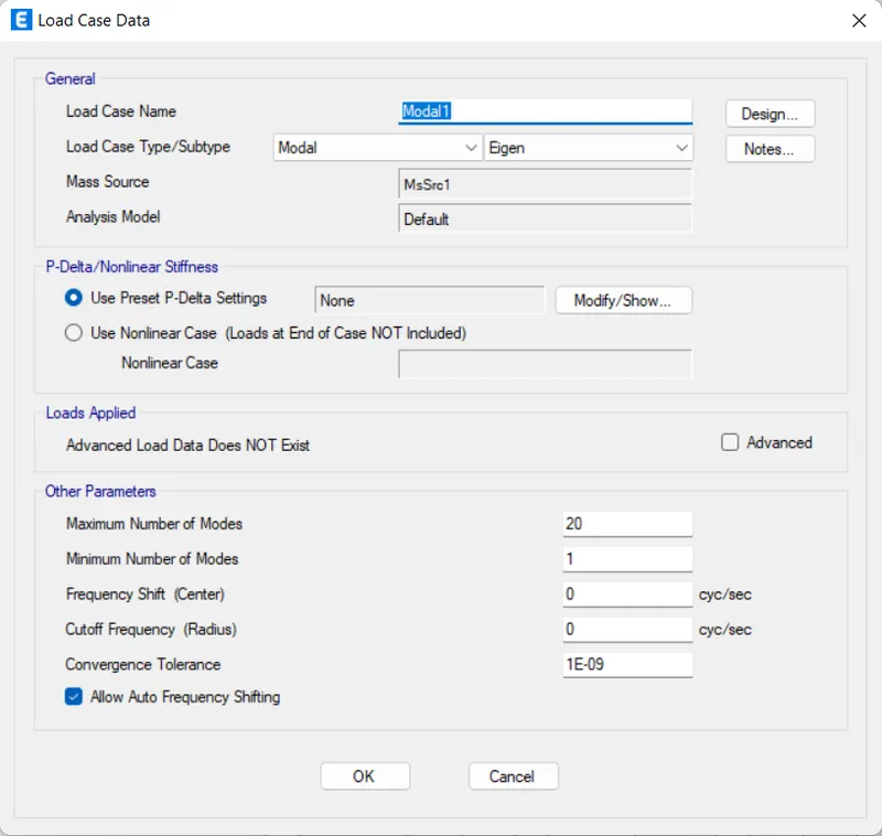
Load cases:
Modal1:
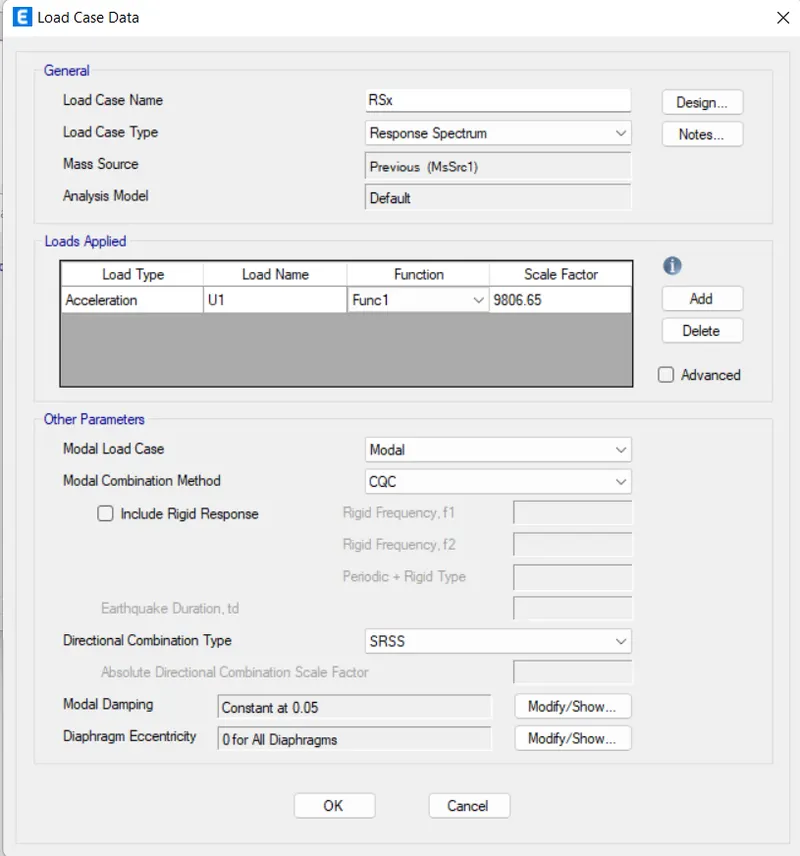
The Response Spectrum Load Cases in X- Direction: Rsx
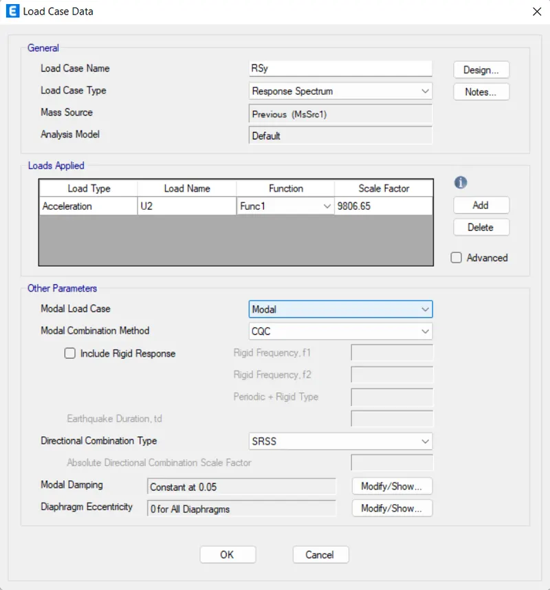
The Response Spectrum Load Cases in y- Direction: Rsy
Check model:
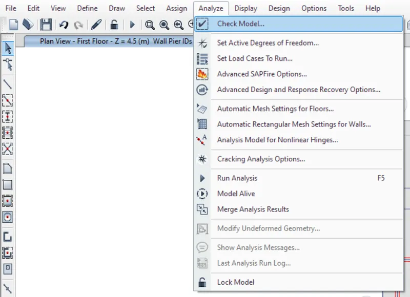
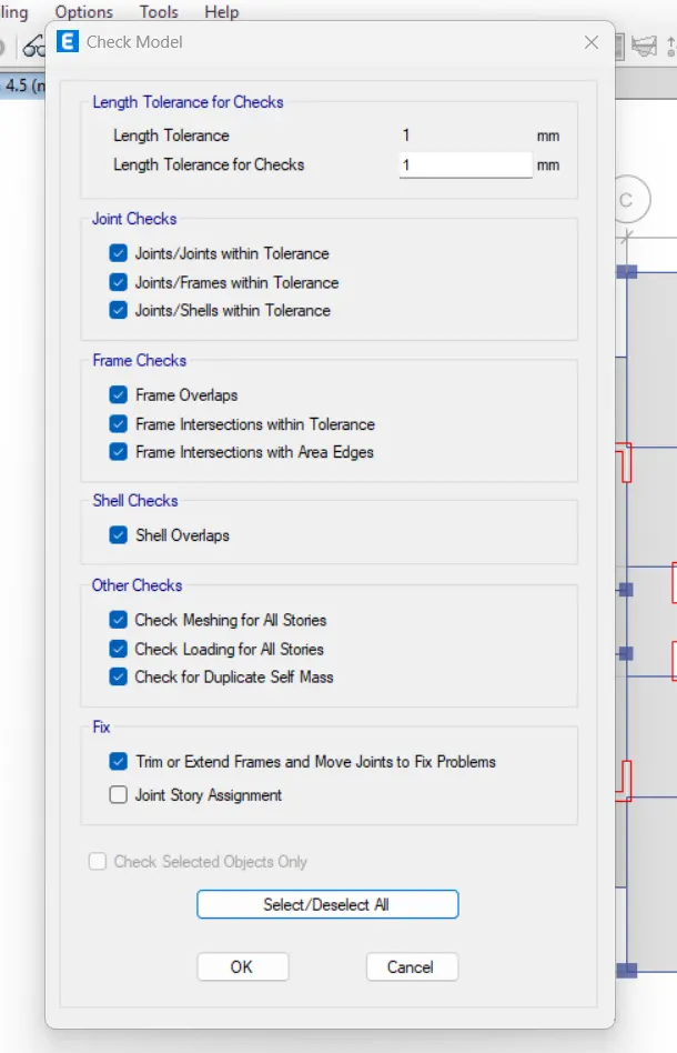
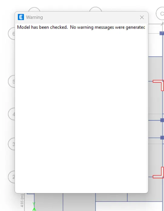
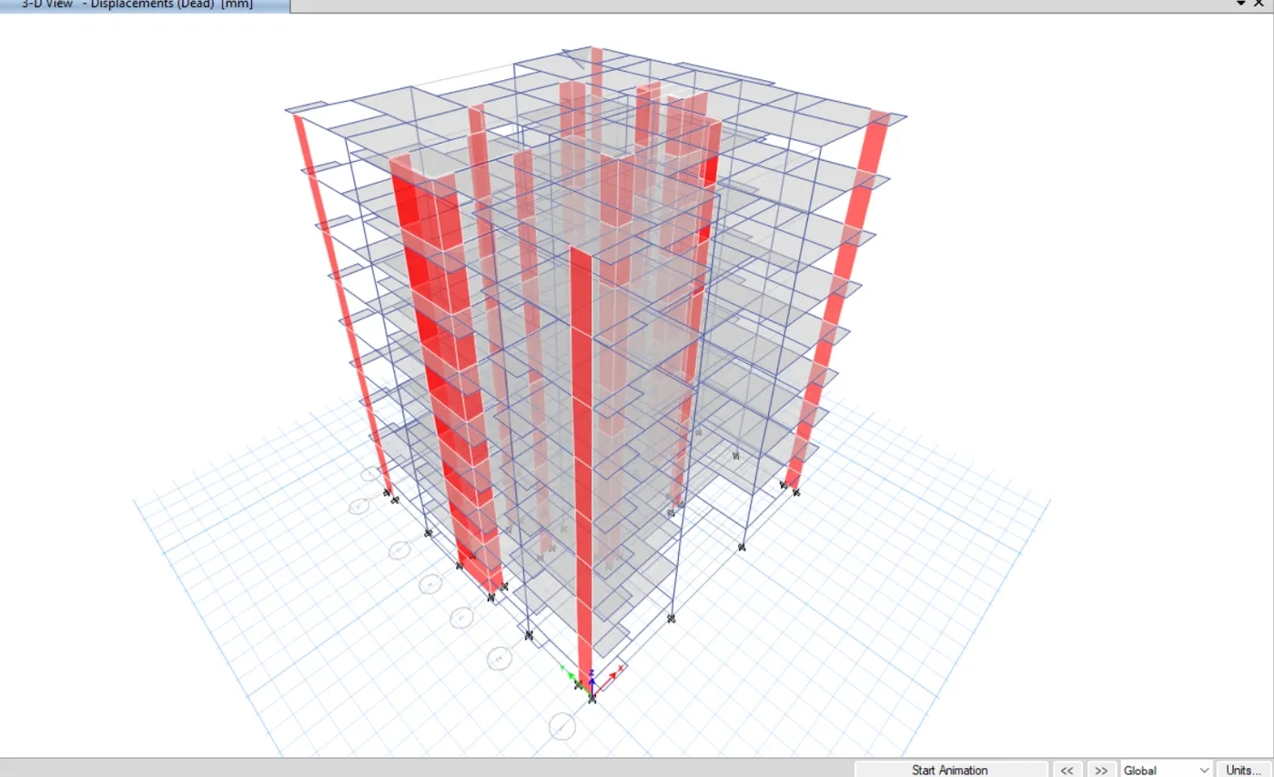
After checking the model with no warning do the Run analysis:
Base Shear Check:
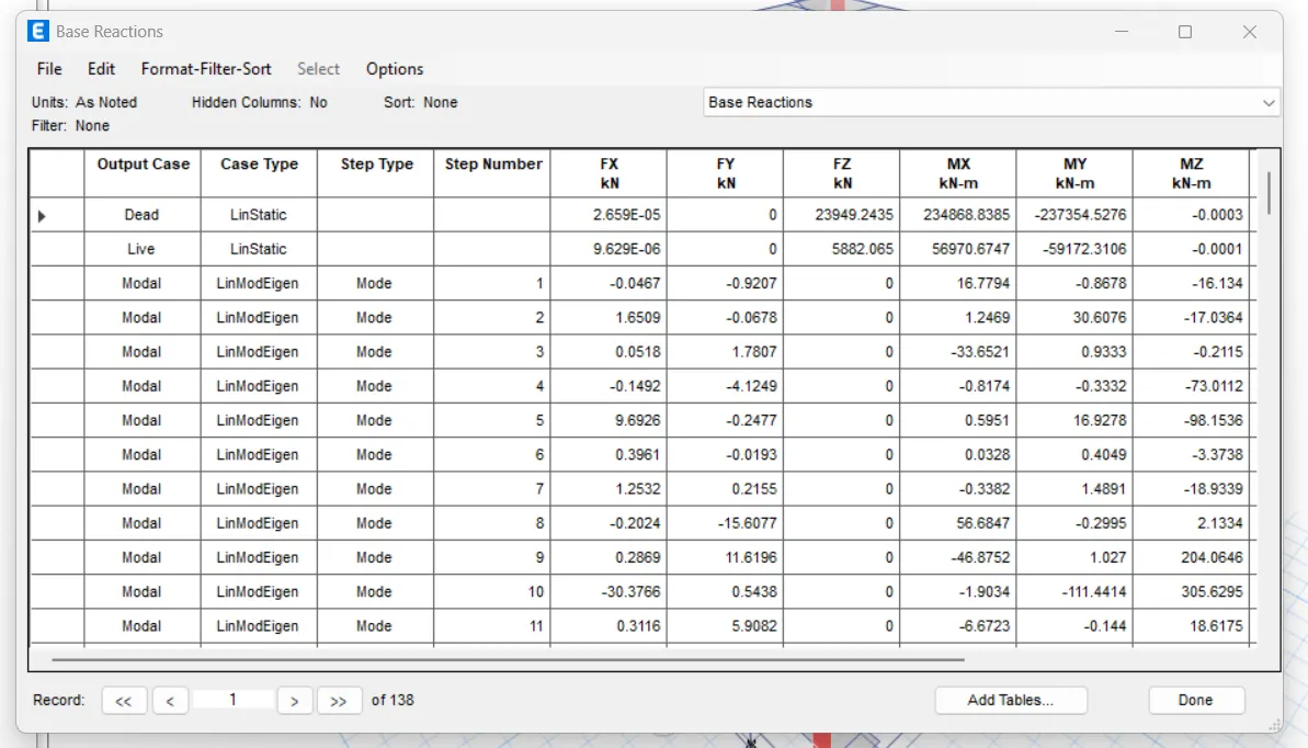
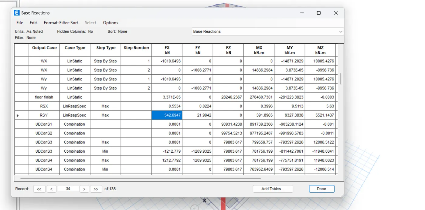
Base shear scalling:
- As we can see from the above image that the response spectrum base shear is less as compared to EQx and EQY.
- So now what we have to do is increase the scale of the response scale spectrum load
Modal Participating Ratio:
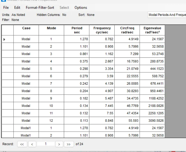
- IS 1893 clause no 7.1 it states that the natural period corresponding to fundamental torsional mode of oscillation should not be greater that sum of two
- So we need to check the participation ratio of the two transational modes only
- Therfore , here Tx= 1.278 and Ty=1.101, TXY =0.864
- So sum of the these two transationa mode of oscillation is 1.278+1.101+0.864 =3.243
- So the sum of the two transational mode of oscillation is 3.24 which is greate thatn the value of TXY whose value is 0.861, hence there is no torsional irregularities.
Story Response Spectrum:
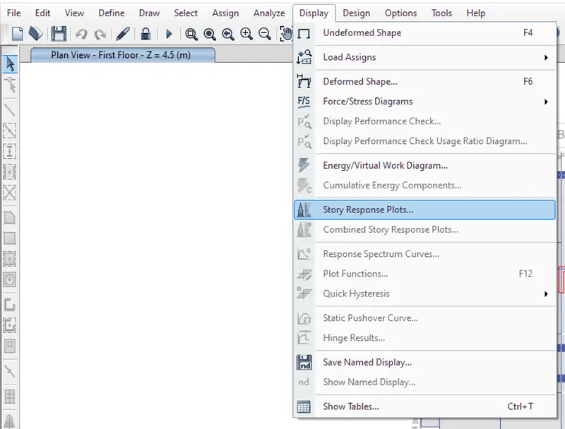
- Display type as Maximum story drifts and case/combo as RSx
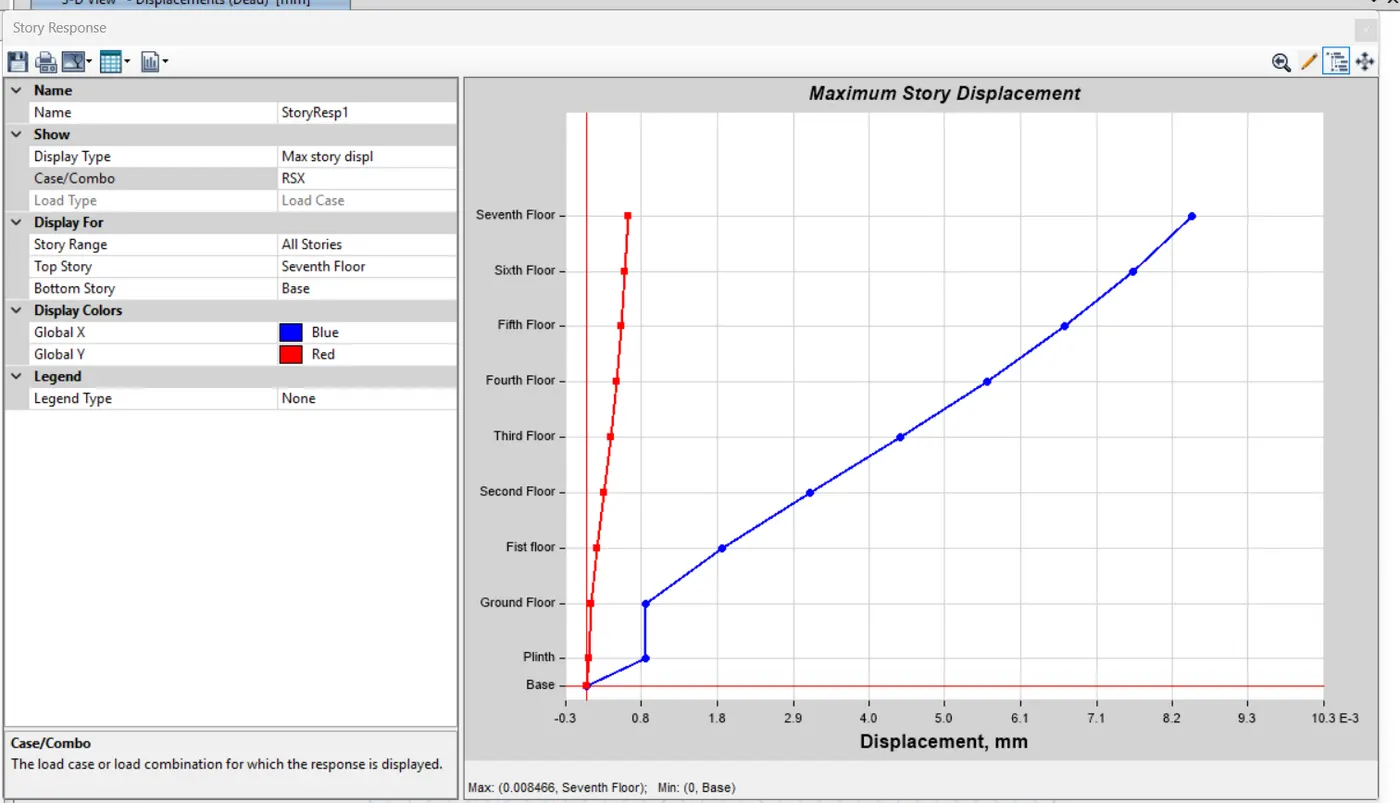
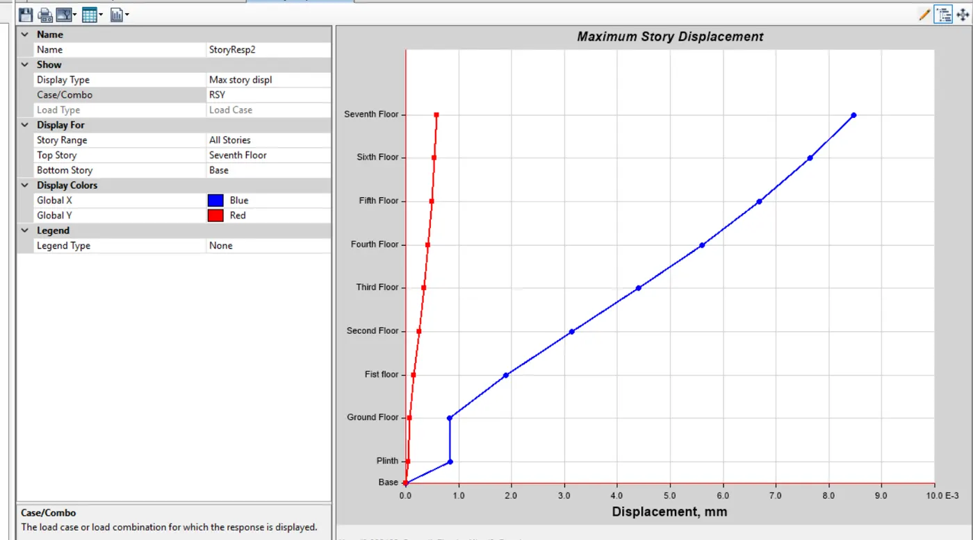
- Now here in our structure the number of shear walls is sufficient .
- Finally the model has been analysed successfully.
Reactions Opens, after that in the dialouge box select the earthquake load lowards the X- direction nd then click Apply and then OK. Just as shown in the below given image:
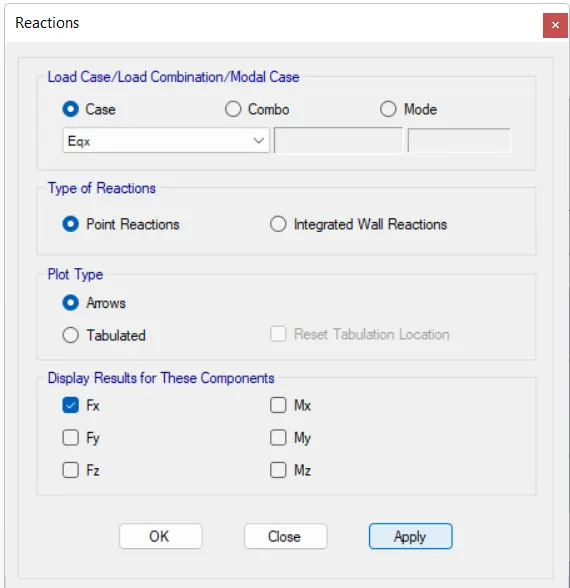
- And from the IS code we know that the shear wall should take at least 80% of the load
- The base shear reactions are shown in the below given images:
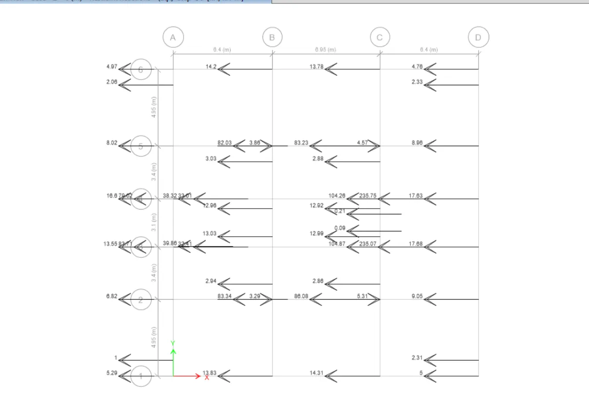
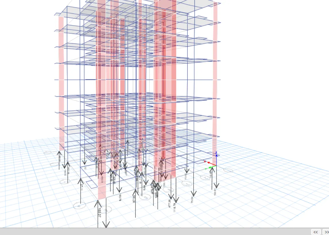
- in order to find the percentage value for the load capaccity of the shear wall divide the base shear wich is take by shear wall with the base shear of the building and is the number of the percentage is less than 80% then there is no need to provide more shear wall in our structure.
- Now here in our structure the number of shear walls is sufficient..
- Finally the model has been analysed successfully.
RESULT:-
- The structural model of the G+7 model is designed for given architectural planning using ETABS:
- Frame model which satisfies both code provison are analysed.
- Column, shear walls and beams are provide in possible symmetric way without much offsets
- Internal-Storey Drift within permissible limits as per IS 1893
- Vertical & Planner Irregularities Checked
- Shear wall Requirements Adequate walls provided for lateral stability.
- Effecive Moment of Inertia verified to ensure realistic stiffness distribution.
- As per the analysis result , building bit flexible in Y-axis as, shear wall are sufficent add aditional column as provided in Y-direction to meet the maximu storey drift limit.