Structural Modelling using Etabs 2018
AIM:
- To model an apartment with all seismic considerations, based on given architectural inputs.
- To know how to check the seismic performance of an apartment using ETABS.
Given Data:
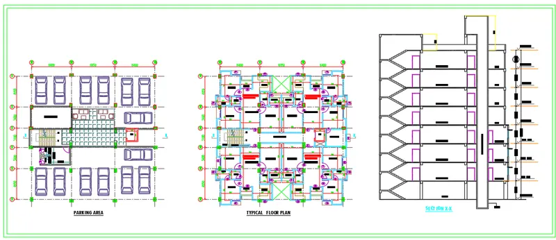
The architectural drawings for a G+7 residential building in zone 5 has been provided. The floor plan is the same for all 7 floor levels. Possible column positions have also been provided. Conceptualize a framing plan layout and then model the building in ETABS. The following architectural drawings have been provided:
- Typical floor plan – The location and thickness of the brick walls and the use of the space (for estimating live load) can be obtained from this plan
- A building section through the staircase and lift core is provided
- Parking layout in the ground floor – the column/shear wall arrangement must not obstruct entry/exit of vehicles.
The following loadings are to be taken into account:
- Brick wall made of AAC blocks
- Finishes – floor tiles of 75 mm thickness
- Live loads as per IS 875 part 2
- Water tank of 20 KL above the staircase at Mumty level
- Lift Machine room at mumty level above lift core
The structural model must comply with provisions of IS 1893 and IS 13920. Run a modal response spectrum analysis and check analysis results of the ETABS model for inter-storey drift requirements, vertical & planar irregularities, minimum shear wall requirements, maximum axial load ratio for column and shear walls, effective moment of inertia for beams and columns etc.\
Please note that the column positions shown in the architectural typical floor plan are only to provide an initial starting point for modelling. Participants will have to change its size, introduce shear walls, and add new vertical elements after running the analysis. You will have to run the analysis multiple times until a structural model is obtained that meets structural code requirements without compromising architectural functions. Also, there is no one ‘correct’ structural system for this challenge. There can be multiple possible solutions for this problem.
Procedure:
Data required for ETABS analysis :
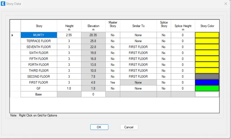
- Pinned support, Base + 9 storey (Ground to terrace) + 1 Mumty
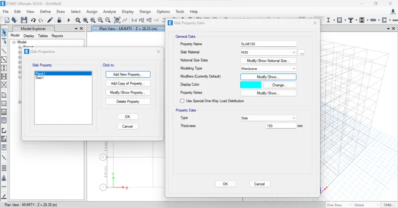
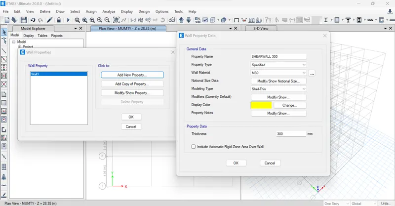
- Column 450mm x 600mm, Beam 400mm x 500mm, Slab 150mm thick, Shear wall 300 mm thick.
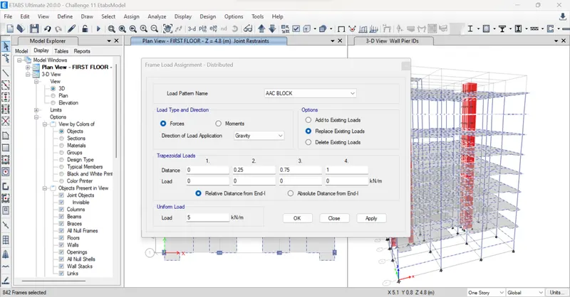
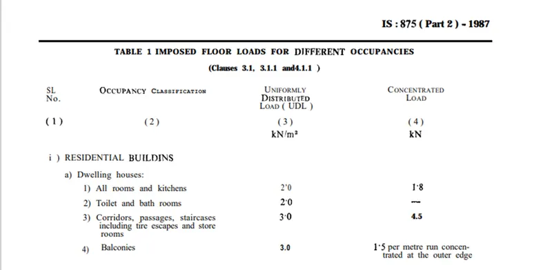
- Live load 2.5KN/m2, Floor finish 1.5 KN/m2, Wall load 5kN/m, Water tank 20K liter over mumty equivalent to 200Kn overall load.
Conceptual design considerations before analysis:
- Re- entrant and cutout check and modification.
Large opening in the center of the building due to architectural purpose or for spacing. Since it cannot be modified it has to be compromised with other designs. - Vertical irregularity.
The ground floor is allocated only for parking with less stiffness and mass compared to other levels of the building. So, it is soft storey mechanism. - Planar irregularity:
The plan looks symmetrical with almost same dimension in both X and Y direction. - 2% Shear wall area with respect to building area, as per IS 1893 (8m2)
- Stiffness modifier for column, Beam and shear wall. (0.35 for beam, 0.7 for column)
Layouts:
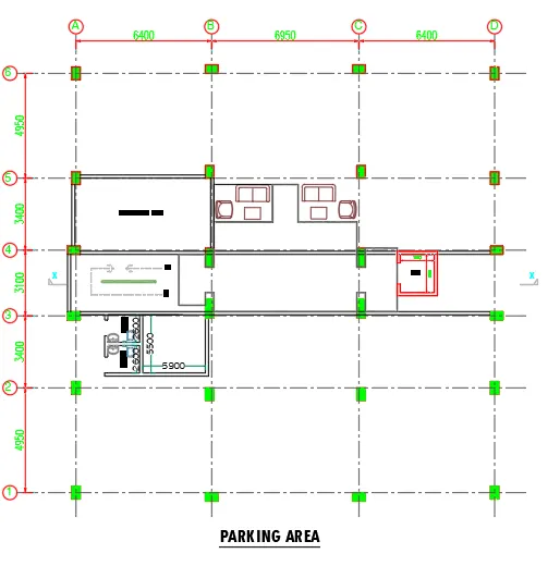
- Open the given plan.
- Add grids as required
Modeling in ETABS:
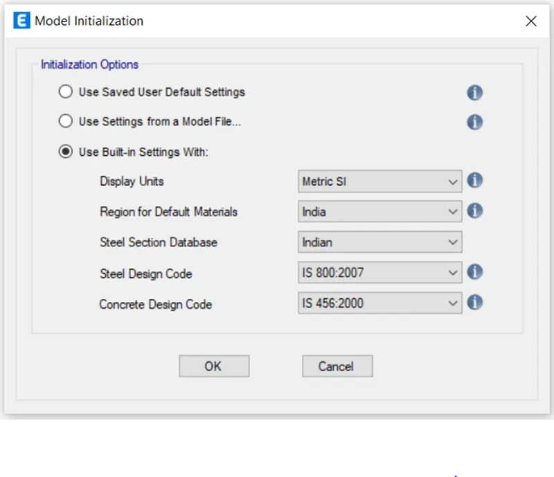
- Open the new file with following settings.
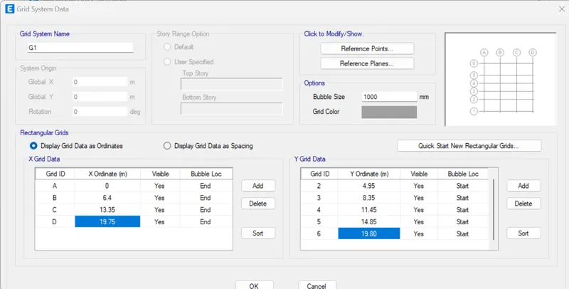
- In New model quick templates dialog box select Edit grid data to create grids in X and Y direction and select Edit storey data
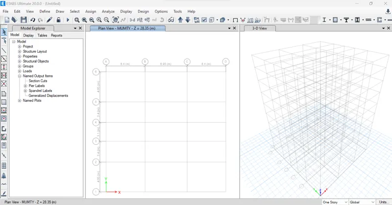
- After formation of grids the following screen opens.
Defining Material properties:
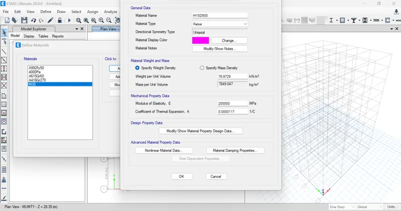
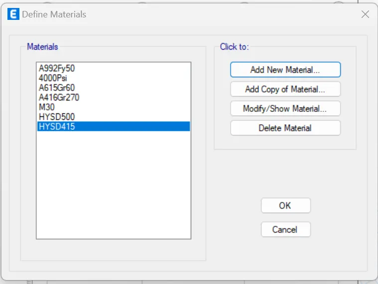
- For selecting material for rebars, Click Define-> Material properties-> Add new material->concrete and Rebar
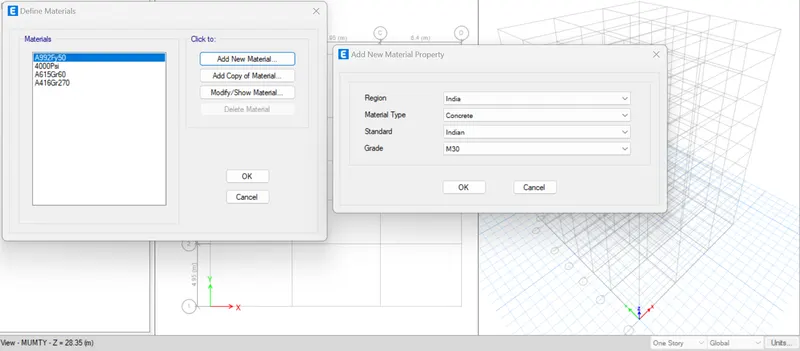
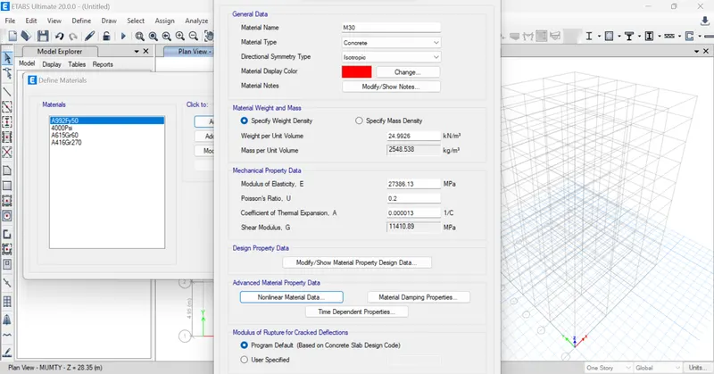
- Click ok and select new material for Rebar.
Defining Section property:
For beam
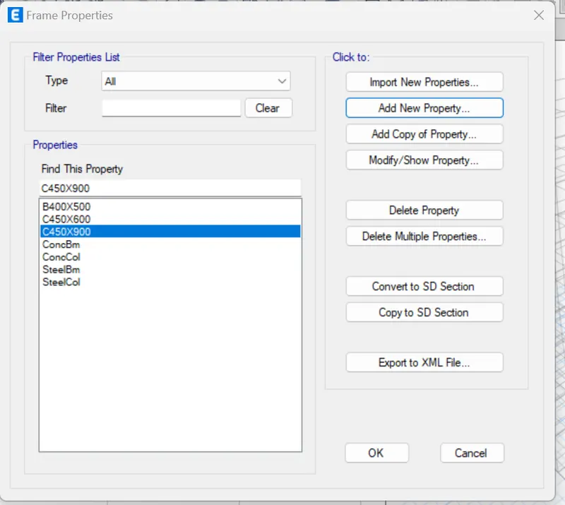
- Click Define ->Section properties -> Frame section -> Add new property.
- Select the shape as rectangle
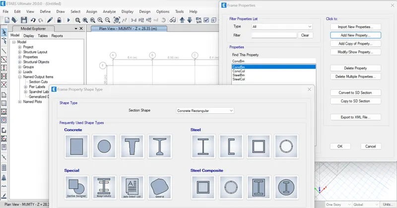
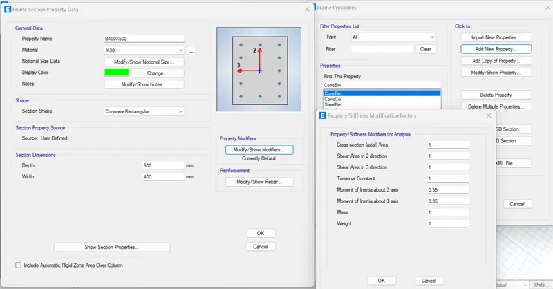
For column:
- Click add new property
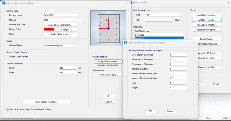
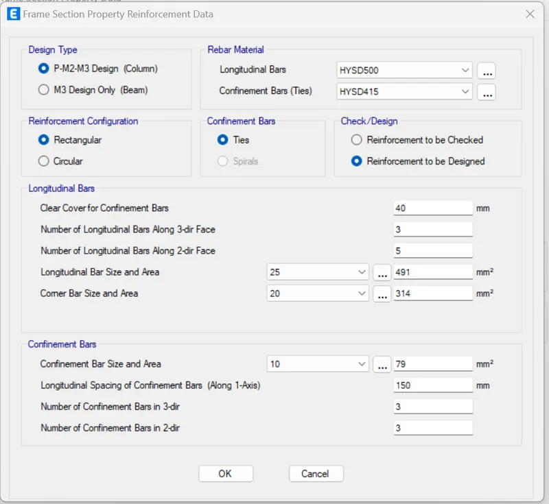
For slab:
- Go to Define -> Section property -> Slab section -> Add new property.
For shear wall:
- Go to Define -> Section property -> Wall property.
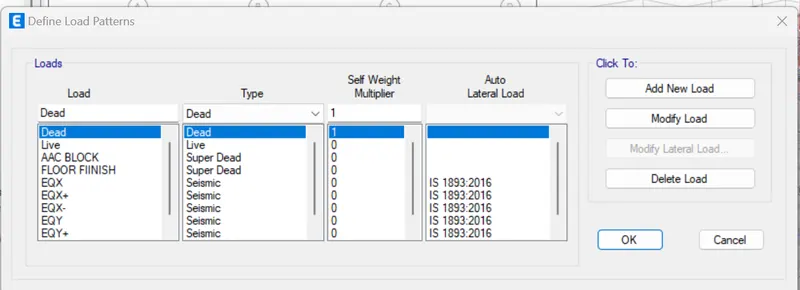
Defining load patterns:
- Go to Define-> Load patterns
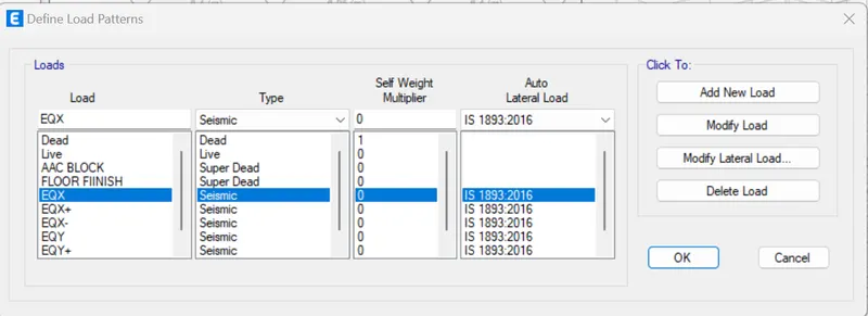
- Enter additional loads and give above data and click add new load.
- Click Modify Lateral Load for both seismic types respectively.
- For all the direction:
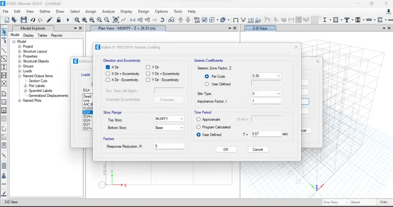
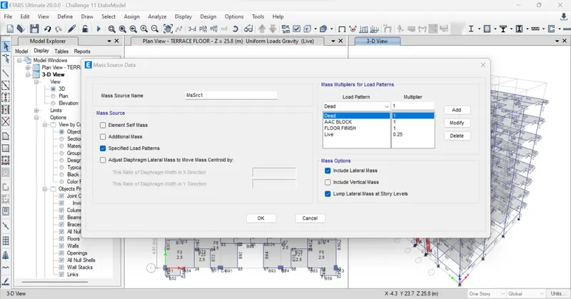
Defining mass source:
- Go to Define -> Mass source -> Modify/ show mass source
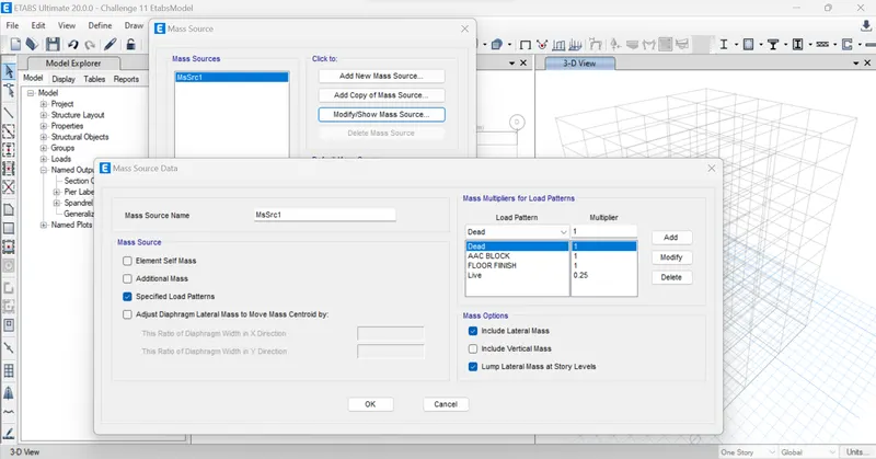
- Add mass multiplier for load pattern as above and click ok.
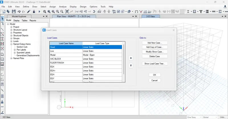
Check the load cases:
- Go to Define -> Load cases.
Create load combination:
- Go to Define -> Load combination ->Add default design combination.
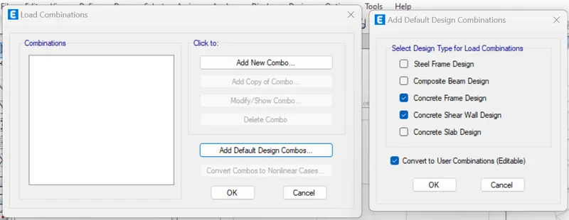
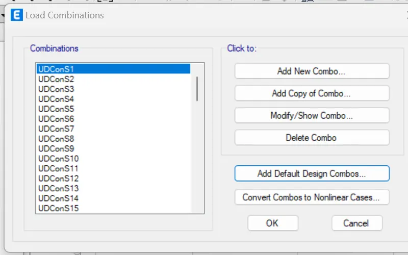
- Combination has created.
Modeling:
To create Column:
- Select Quick draw column icon in the panel and select the column property type as C450X600.
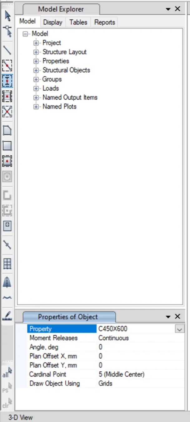
- Select All stories option in the bottom right.
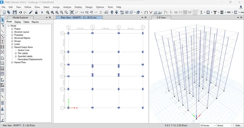
- Move the cursor on the grid and click to create column as shown below.
- To change the particular column orientation, select the columns to be changed and click Assign -> Frame -> Local axes -> Rotate by angle as 90.
To create beam:
- Select Quick draw beam icon in the panel and select the beam property type as B400X500.
- Select All story option in the bottom right.
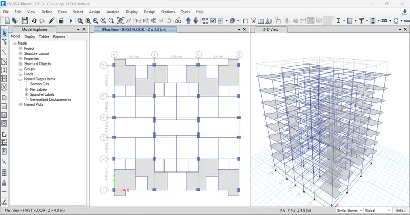
- Move the cursor on the line in between the grids and click to create beam as shown below.
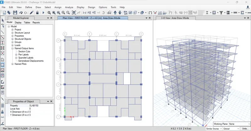
To create slab:
- Select similar stories option in the bottom right.
- Click plan icon on top of the panel and select the storey 1.
- Select Quick draw floor icon and select slab property type as S150.
- Click inside the frame.
To Create shear wall:
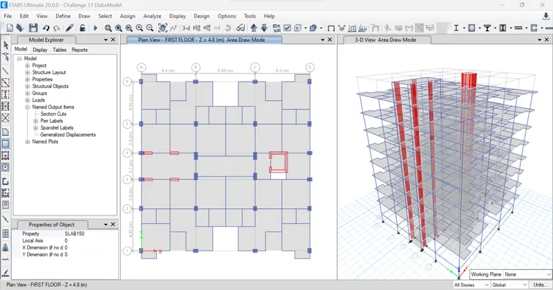
- Click Draw wall command-> Shear wall 300 as property
- Pick both end point of the grid to draw shear wall as shown below.
To give pier label to the shear wall:
- Go to C Elevation and keep All stories as status
- Select the shear wall
- Click Assign -> Shell -> Pier label -> modify/ show definitions -> Enter name.
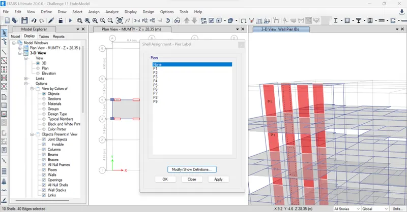
- Follow the same procedure to give name to the rest of the shear wall.
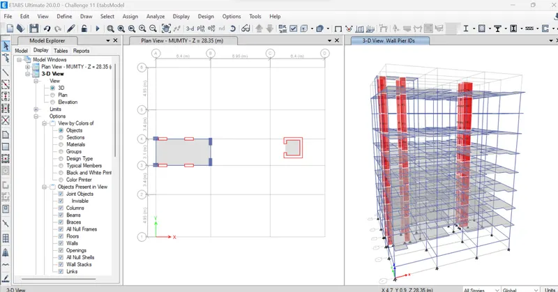
To assign the Joints :
- Select set of particular joints assign the Fixed
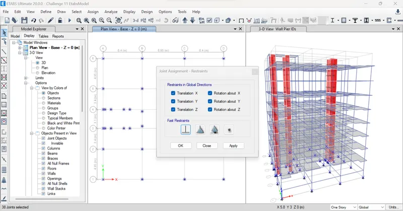
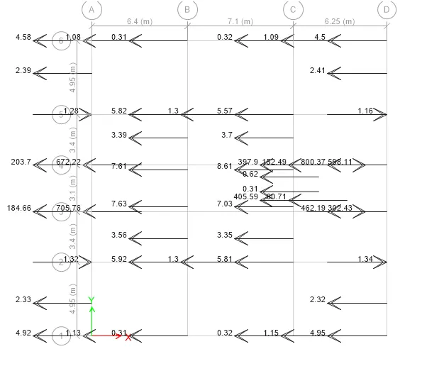
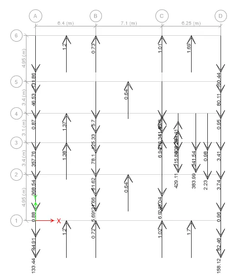
To assign the loads:
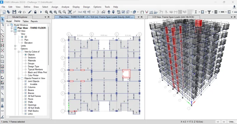
- Select set of particular elements and assign loads.
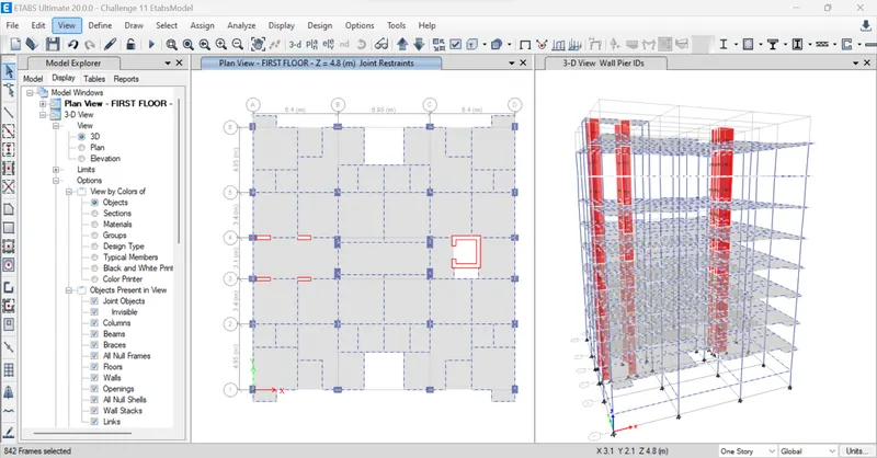
Beam:
- Go to Select -> Select -> Property –> Frame section
- Select the beam type.
- Go to Assign-> Frame loads-> Distributed.
- Give load pattern and load as mentioned above.
Slabs:
- Select slab property as S150
- Go to Select -> Select -> Property –> Slab section
- Go to Assign-> Shell loads->Uniform.
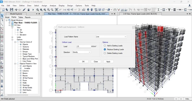
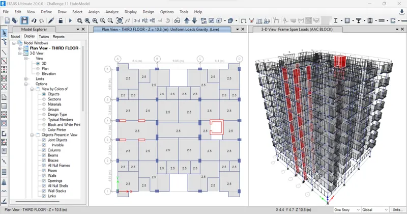
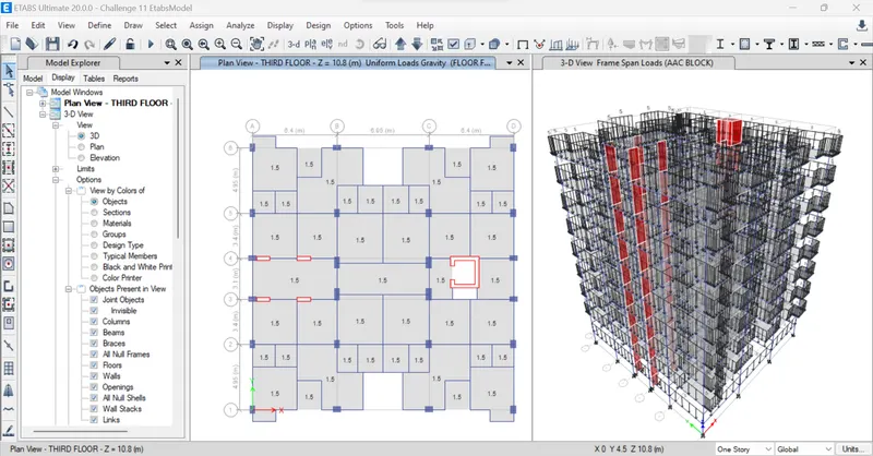
- For Floor finish- Follow the above same procedure.
To assign Diaphragm:
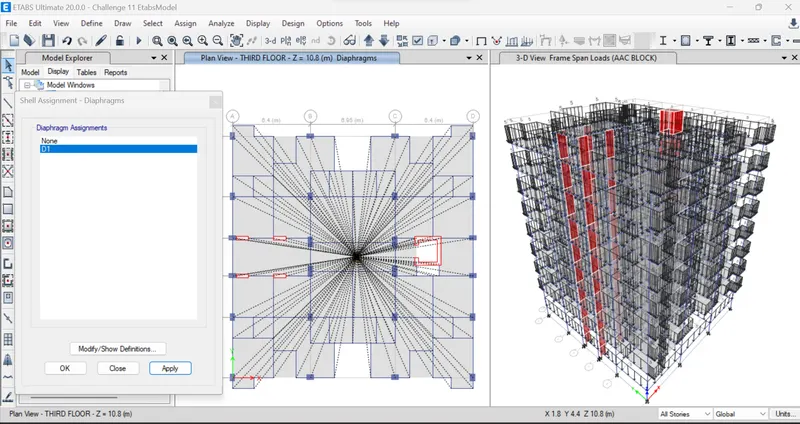
- Again, go to Select -> Select -> Property –> Slab section
- Select Assign -> Shell -> Diaphragms -> D1.
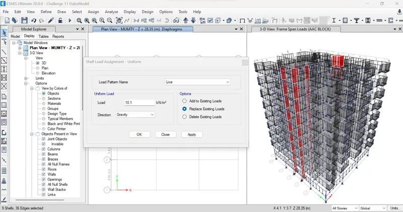
Adding Water tank of 20 KL above the staircase at Mumty level:
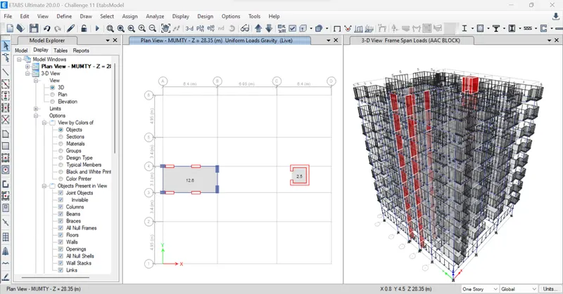
- Area above the staircase at mumty level = 3.1m x6.4m= 19.84m2.
- 20 KL= 20T
- Hence, 20T = 200 KN
- =200/ 19.84= 10.1 KN/m2
- Apply it as live load.
- Select the slab and click Assign -> Shell loads -> Uniform
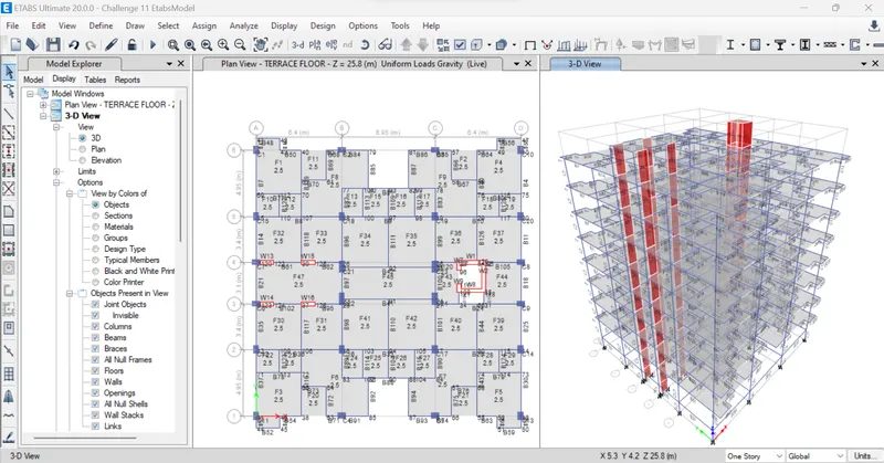
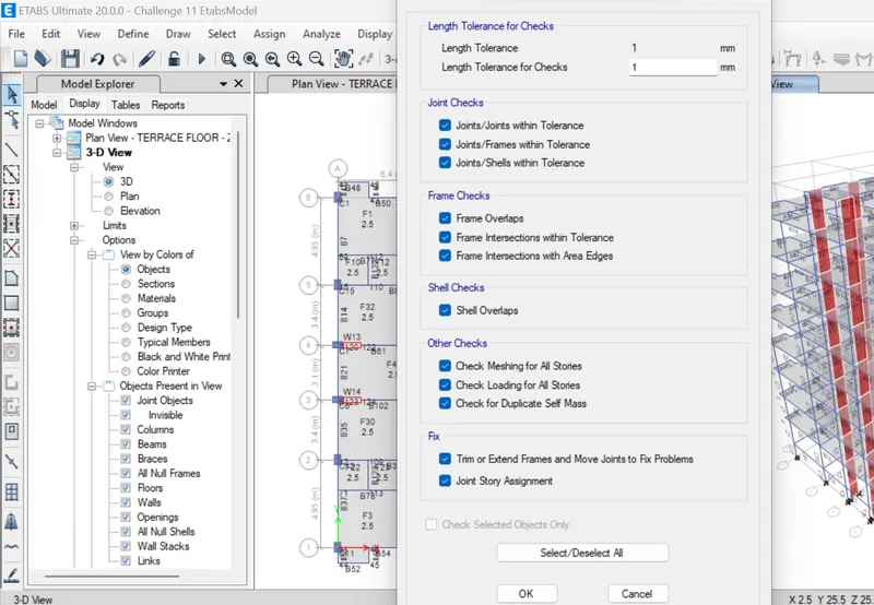
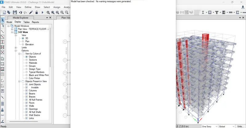
- Checks are to be done before running the analysis.
- All the beams and column sizes and assignments are checked
- Load pattern:
- Live load as per IS 875 PART 2 -1987
- Mass source data:
Run Analysis:
- Click Run analysis button on the top panel.

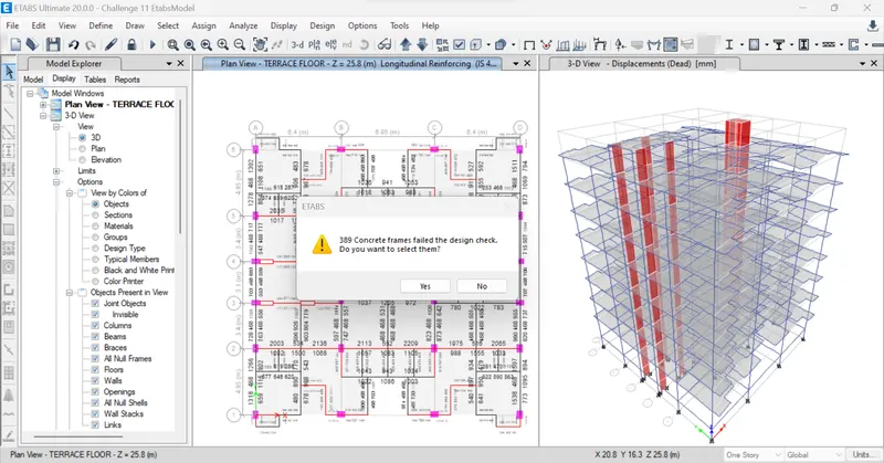
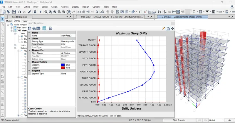
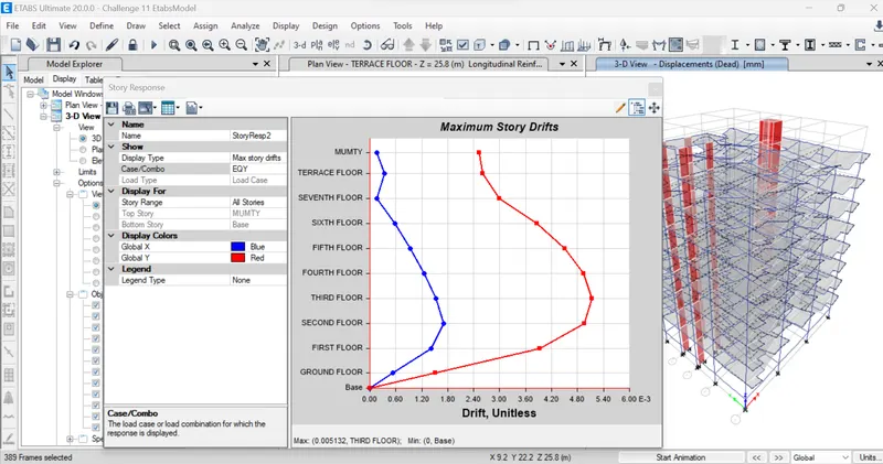
- Go to Display -> Story response plot.
- Select Max story drift and EQY
Response spectrum method:
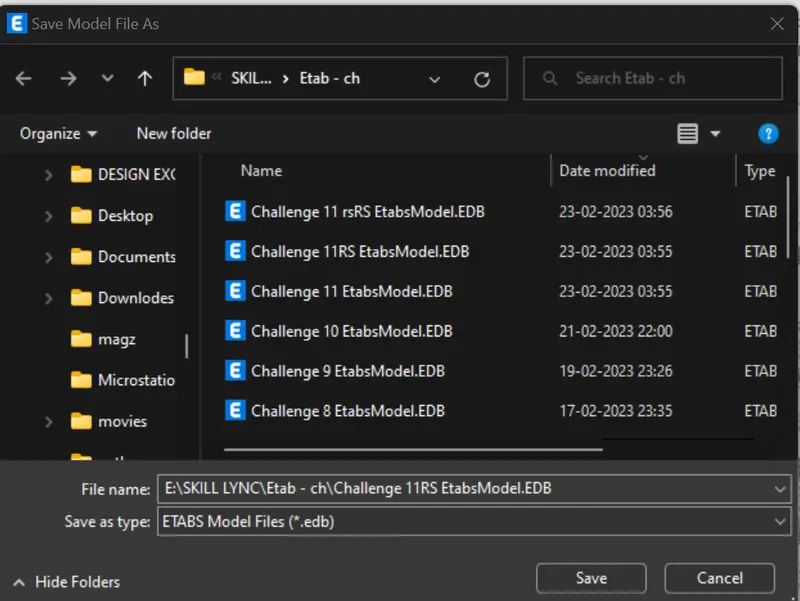
- Save as the project
-
- Delete the created EQX and EQY
- Create new load cases as RSX and RSY.
- Define -> Function -> Response spectrum.
-
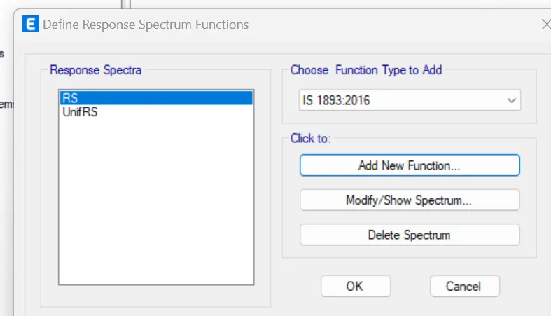
- Give the below settings.
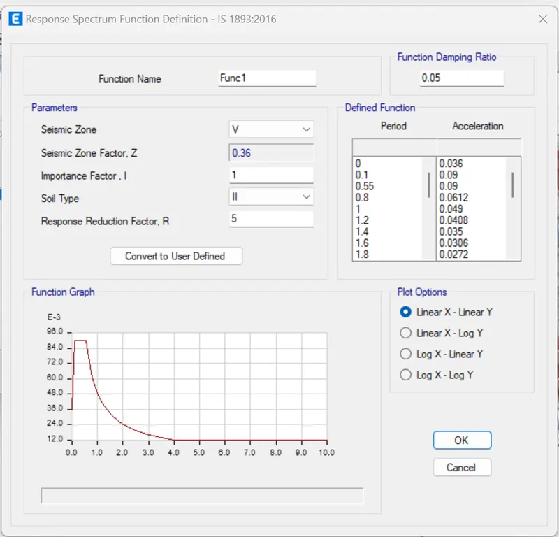
- Go to define -> Load cases
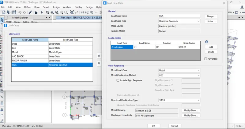
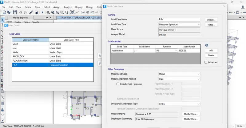
Run the analysis:
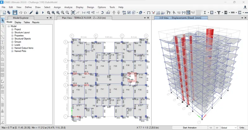
Result:
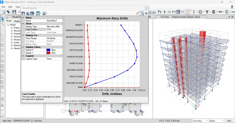
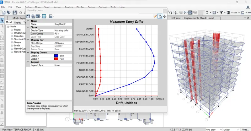
Story drift:
- Go to Display -> Story response plot.
- Select Max story drift and RSX AND RXY
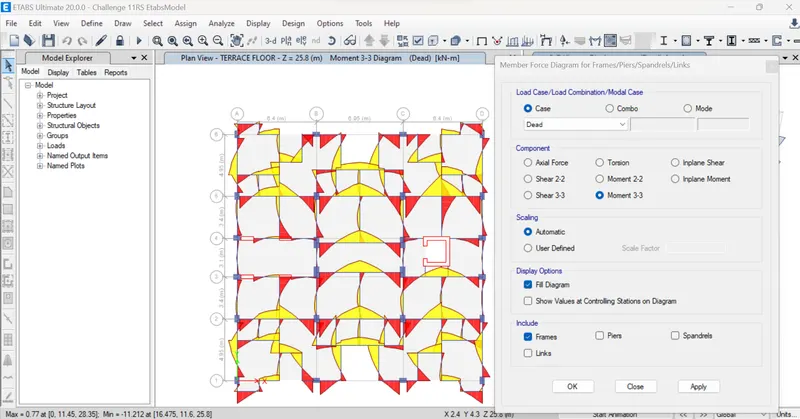
- Shear force AND Bending moment:
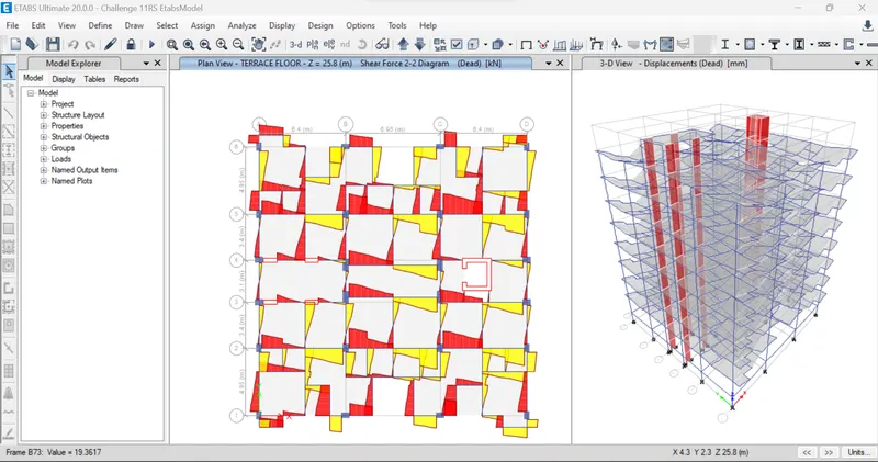
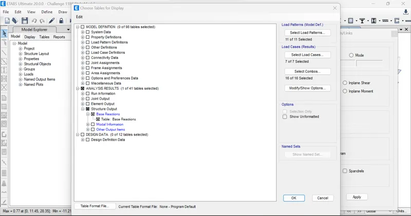
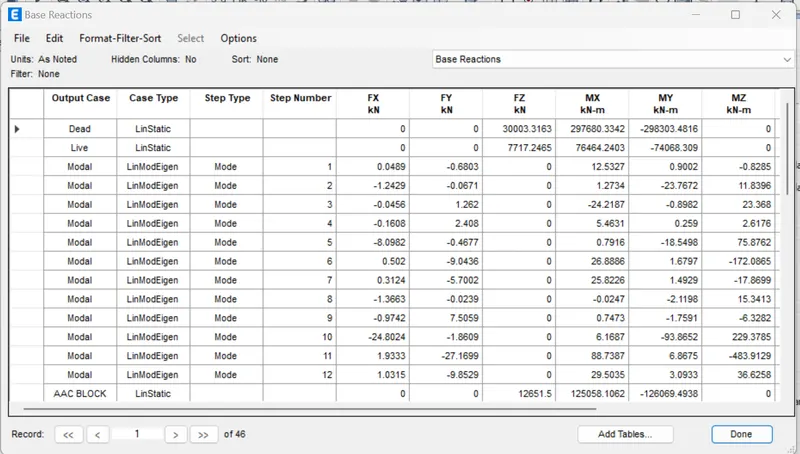
Base Shear is grater than 80%.
Therefore analysis has been done successfully.