Structural Modelling using Etabs 2018
Aim - i) To design a structural model on the basis of provisions from IS 1893 and IS 13920 in seismic zone 5.
ii) To Run a modal response spectrum analysis and check analysis results of the Etabs .
Procedure -
Step 1)
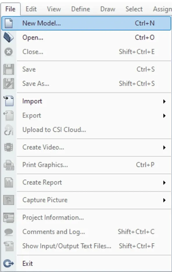
i) We have to open the ETABS software and click on the new model option from the file menu.
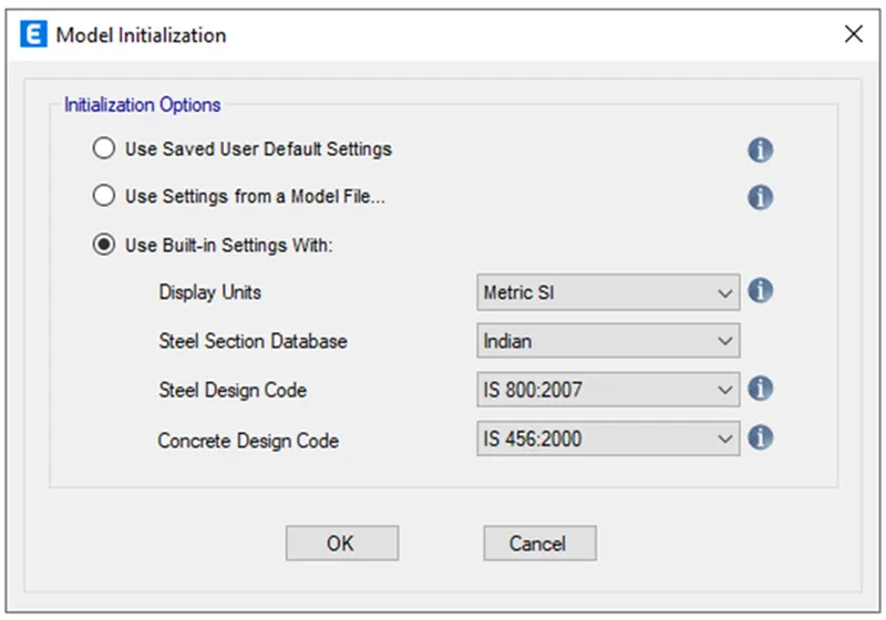
ii) Now in the model initiation window desired units, Design codes which are to be used was selected.
Step 2)
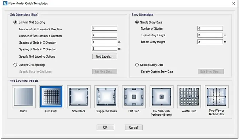
i) In New Model Quick templates under grid dimensions select the custom grid spacing and then click edit grid data.
ii) The grid dimensions were inserted according to CAD file drawing as follows.
Step 3)
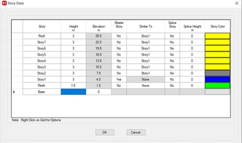
i) Now we have to enter the Story data as per cad files. ( It's G+7 building)
ii) Floor to floor height is given as 3m
iii) For that click on New Model Quick templates under Story dimensions select the custom story data and
then click edit story data.
iv) Now input the storey details as given in question and story 1 was selected as the master story
and was applied to rest story from 2nd story to roof and then click OK.
Step 4)
i) Now we have to define material properties
ii) For that Define the properties of elements - Define menu
iii) Select material properties.
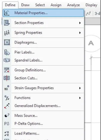
iv) Once you select material properties a following dialog box will appear
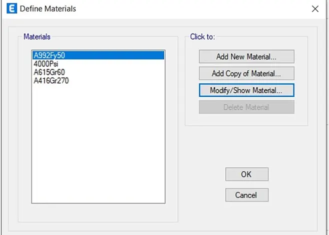
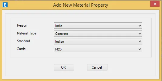
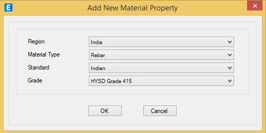
v) Define the materials - Add New material -
vi) Select M25 grade of concrete -
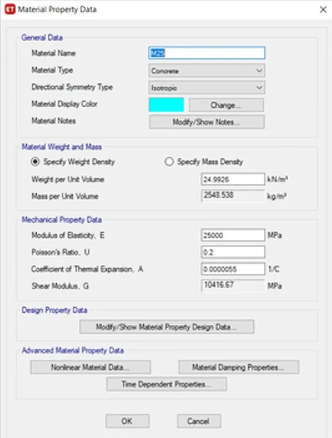
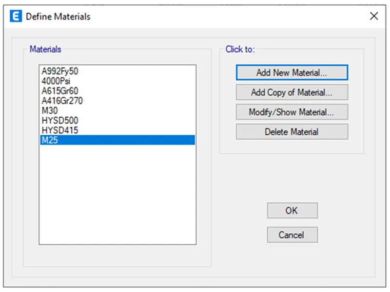
vii) Similarly for Steel select Rebar Steel(HYSD 500 and HYSD415) properties was added to the list now as shown and then click OK.
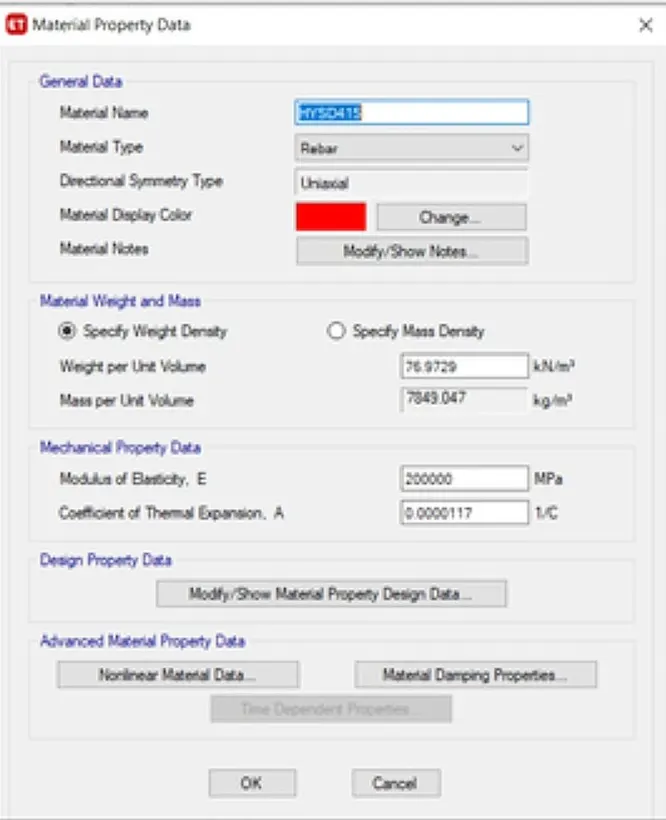
viii) Material Properties is added
Step 5)
i) Now we have to add section properties -
ii) For that Click on Define Properties- Section Properties- frame sections options.
iii) From the frame properties dialogue box click on add new property option.
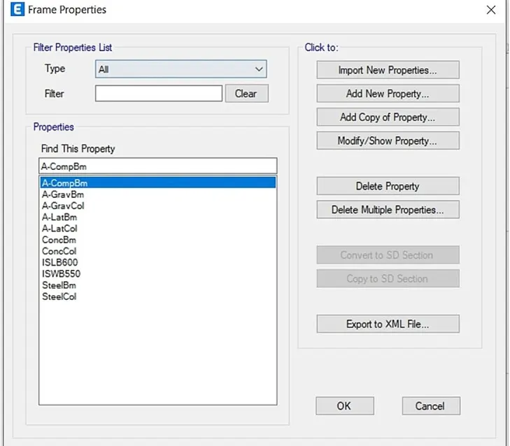
iv) Click on Add new Property
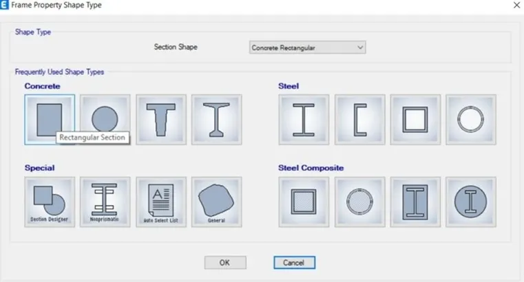
iv) Select frame property shape type select the rectangular concrete option and click OK.
v) Beam details (250X450) was provided as shown in figure and then click on Modify/ Show reinforcement under reinforcement section.
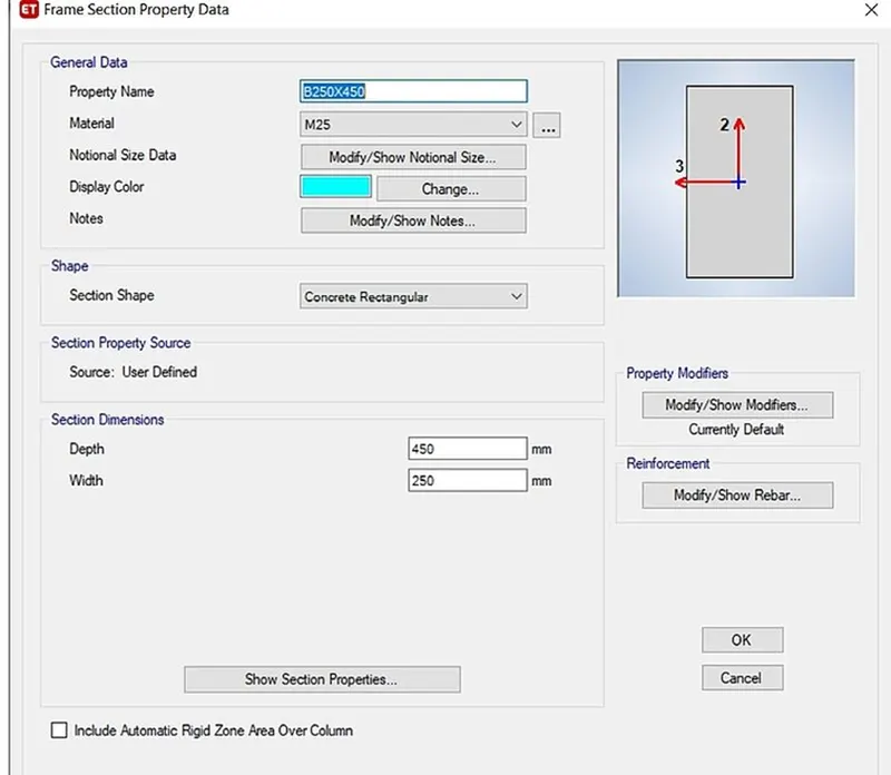
vi) Click on Modify / Show Rebar -
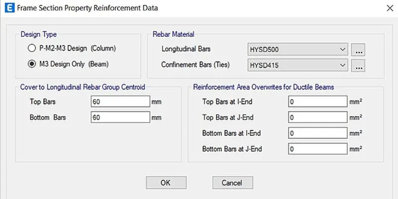
vii) Select M3 Design Only (Beam) and chose the rebar materials as shown and click OK.
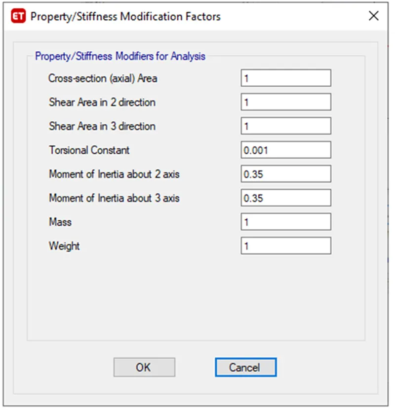
viii) Click on Modify / Modifier
ix) The torsional constant was reduced to 0.001, The Moment of Inertia about 2nd and 3rd axis was reduced to 0.35 respectively.
x) Similarly the beam of size 300x500 is also added by following same steps
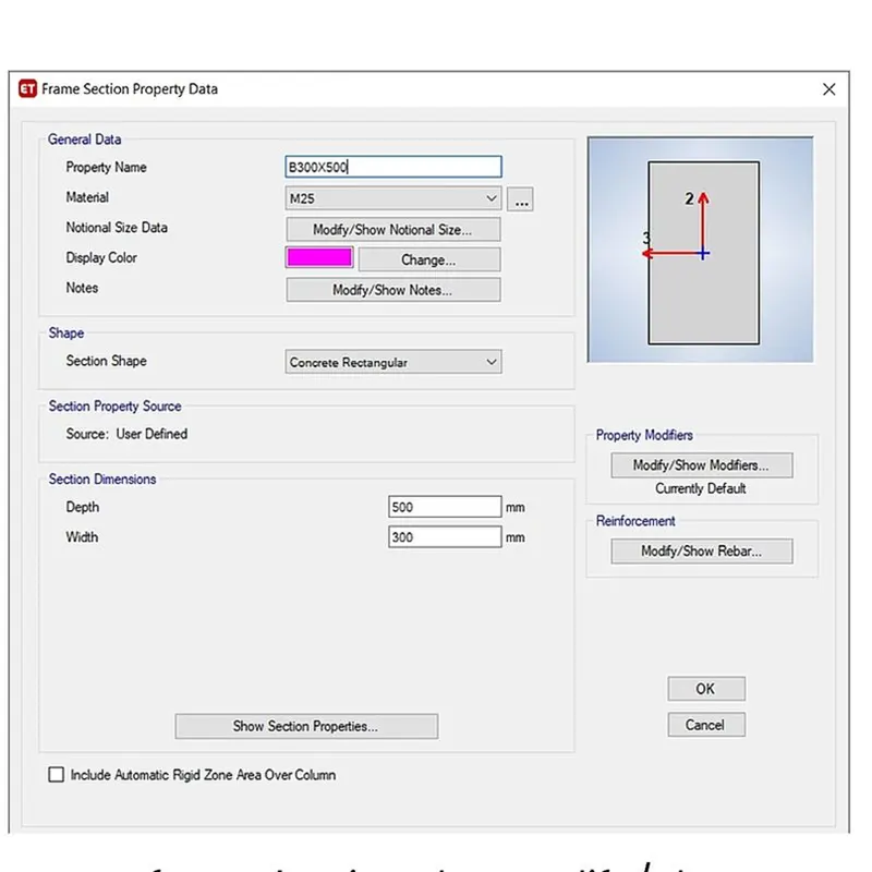
xi) In the similar manner Column properties is also added by following same steps
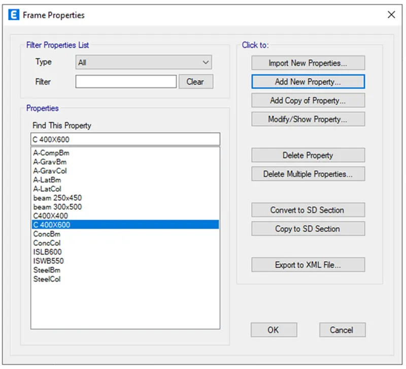
xii) Column 400 x 600 is added as shown below
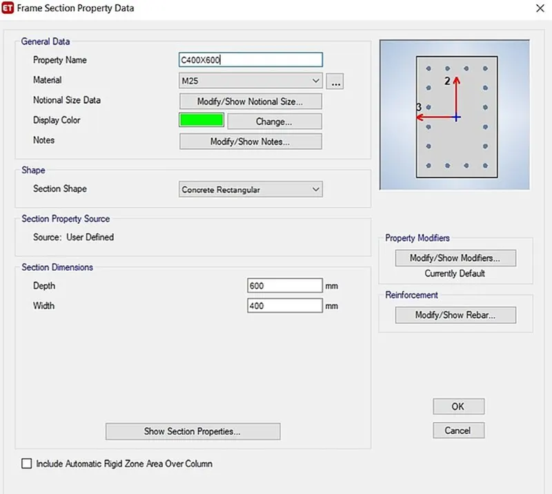
xii) In case of column the Moment of Inertia about 2 and 3rd axis was reduced to 0.75 respectively.
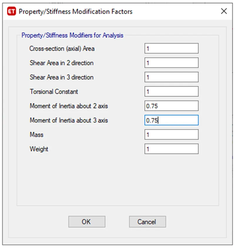
xiv) In the similar way 400X 400 column was also detailed.
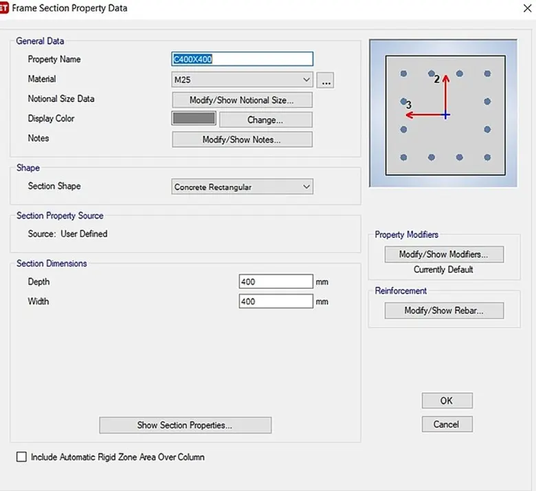
xv) From property list we can see the columns of size 400x400 and 400x600 and Beams of size 250x450 and 300x500 are added.
Step 6)
i) To design the slab initially For Select Slab section from the section properties under Define menu.
ii) Select add new property option.
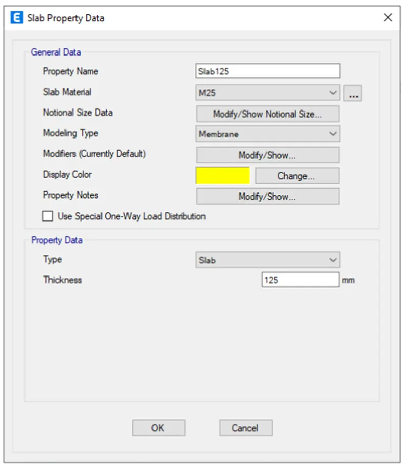
iii) Slab properties like thickness and other details are added as shown below and then click OK.
iv) Give the thickness = 125 mm.
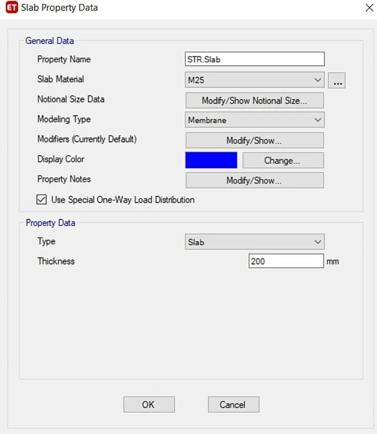
v) Similarly a slab of 200mm thickness is also added for the staircase.
Step 7)
i) Now we have to add the Shear walls
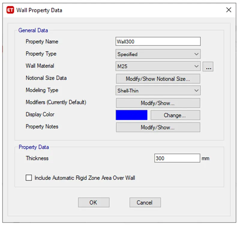
ii) For that click on Define - Section properties- Wall sections-
iii) Assign the Wall thickness as 3000mm
Step 8)
i) First we have to draw the columns by using Quick draw column option -
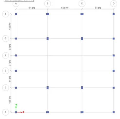
ii) Next we need to add the beams using quick draw beams option as shown below
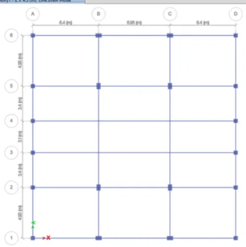
iii) Next we need to add the secondary beams by using quick draw secondary beams option as shown below
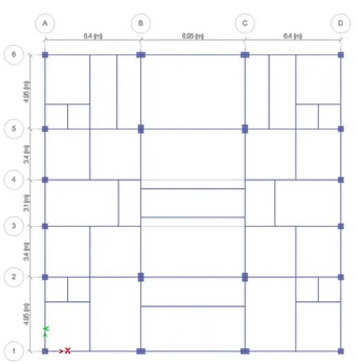
iv) Next we have to add the slab by using Quick draw floor plan / walls
iv) Next we have to add the shear walls in required locations as shown below
v) And add the balcony wherever required
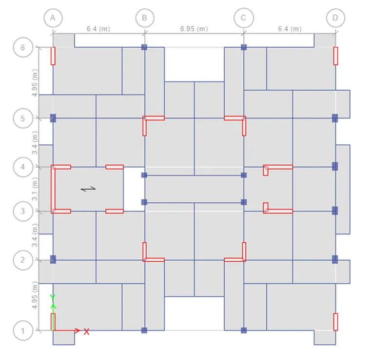
Step 9)
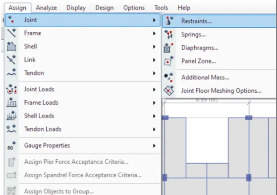
i) Now we go to the base plan and select all base joints
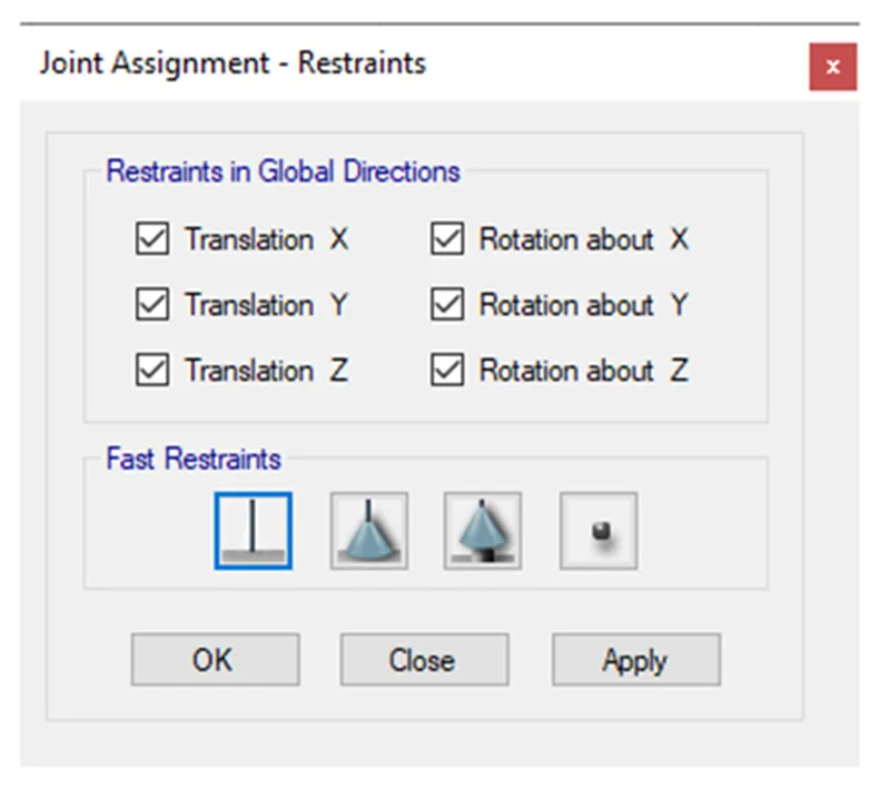
ii) Next we select the restraints from the joint option as shown below
iii) Select the Base connection are fixed
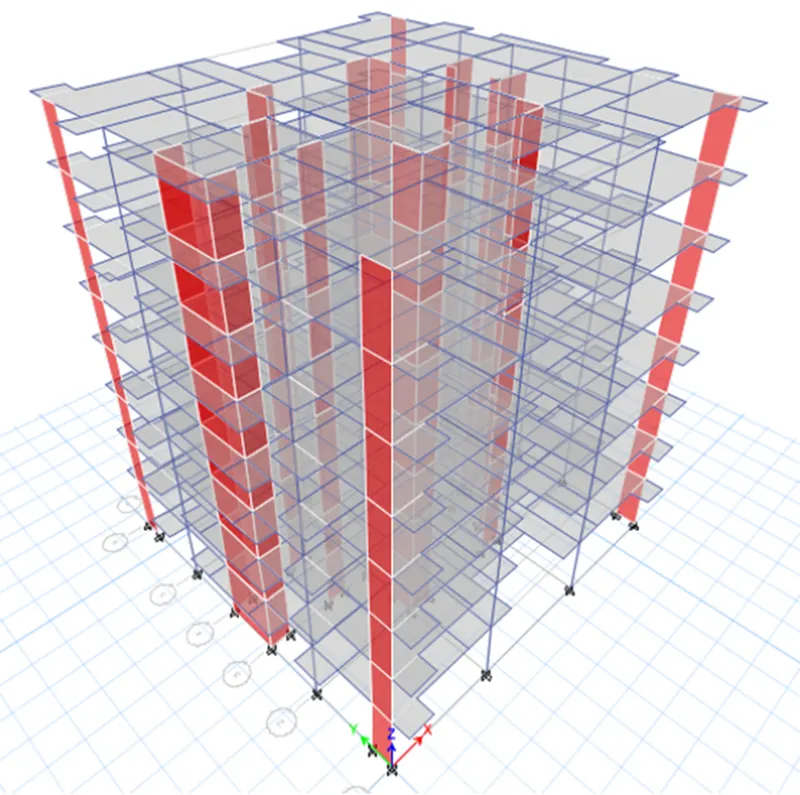
3D view after assigning all properties -
Step 10)
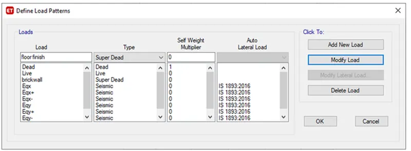
i) Now we have to assign loads patterns
ii) Select Define - by load patterns to open the Define load pattern dialogue box.
iii) The various loads which are applied are as shown below
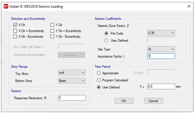
iv) The direction and eccentricity were selected as the X direction.
v) The Response Reduction Factor R was taken as 5
vi) Seismic Zone is 5 so Z = 0.36
vii) Soil type was taken as III
Viii) Importance factor for residential building with less than 200 is taken 1 and time period is taken as 0.5
Step 11)
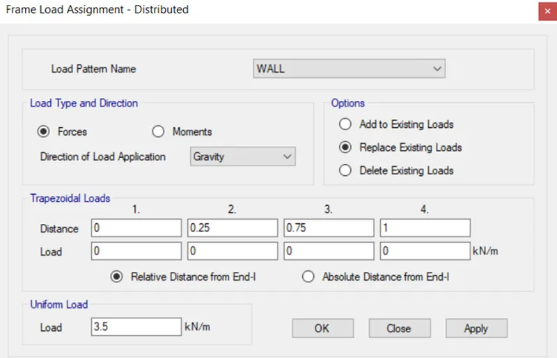
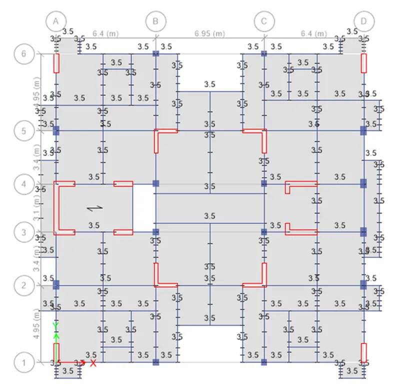
i) Now we have to assign the loads to the strucure -
1) Brick wall load - 3.5 kn/m2
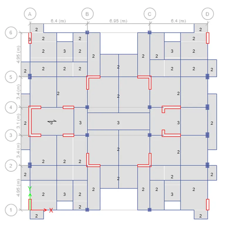
2) Live loads were applied to slabs next.
i) As per IS 875 in residential bui;dings its 2kn/m^2 for rooms and bathrooms whereas it is 3kn/m^2 for staircase, lift and balcony.
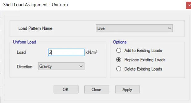
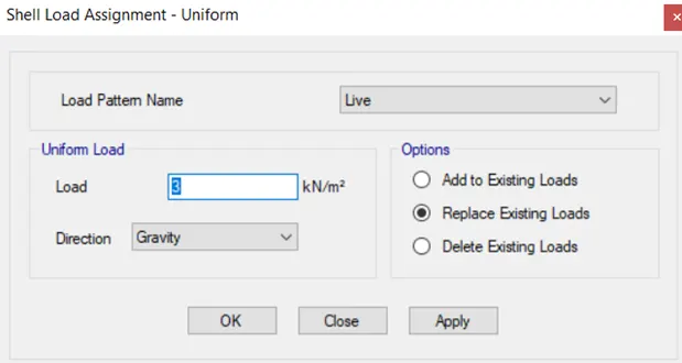
Live loads are applied repectively .
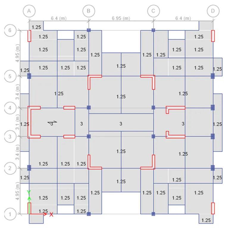
3) Floor Finish
i) In the same way select slabs to assign floor finih which is 1.25kn/m^2 for rooms and bathrooms whereas it is 3kn/m^2 for staircase and balcony.
Step 12)
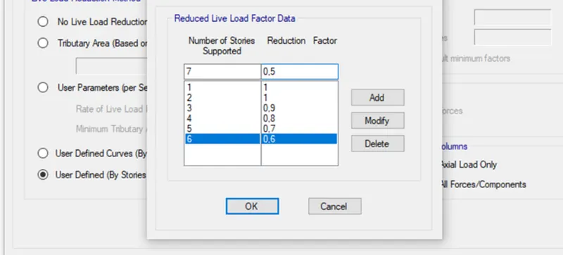
i) Live load reduction factor as per IS 875 code
ii) For buildings above 10 Storey we have to reduce live load by 50%.
Step 13)
i) Now we have to assign Mass source
ii) For that Define menu - mass source options to open the mass source dialogue box.
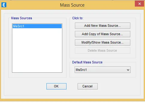
iii) Now select Modify mass source data option and click OK
iv) Now mass source data was provided as shown and load pattern was also added to it.
v) For live load upto 3kn/m2- we have to assume some fraction of live load i.e., 25%
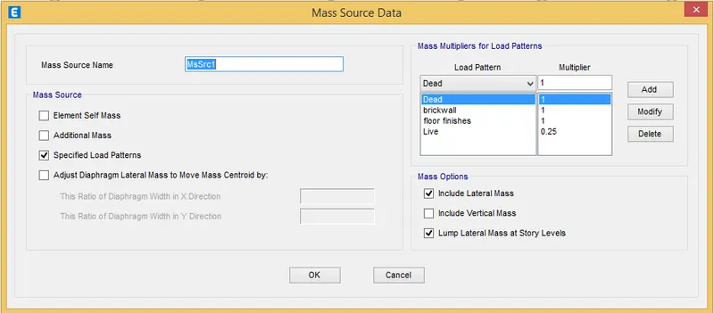
Step 14)
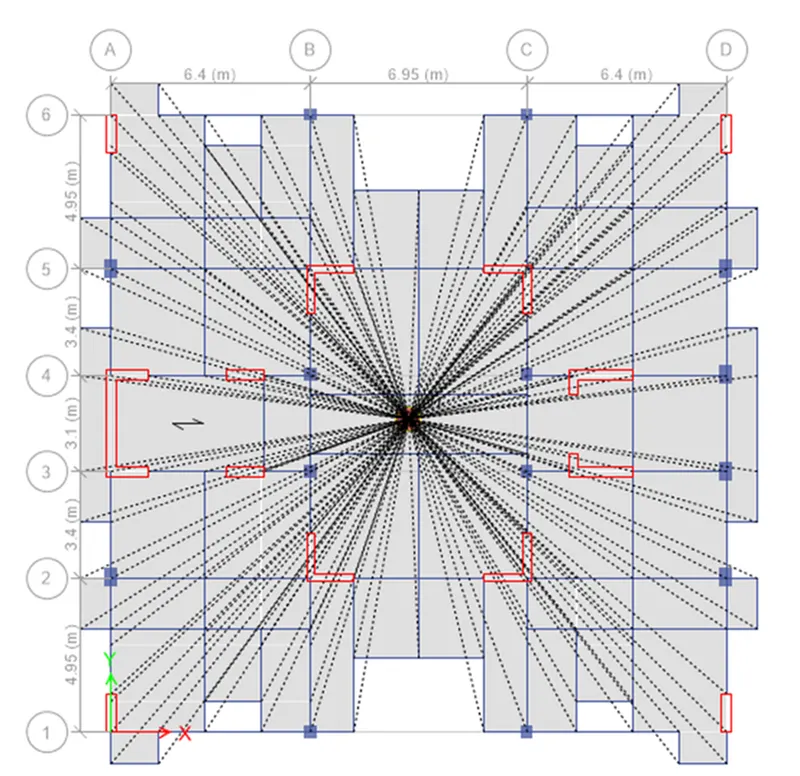
i) Now we haev to assign diaphragm
ii) In assign menu select Shell followed by Diaphragm to open the shell Assignment diaphragm dialogue box
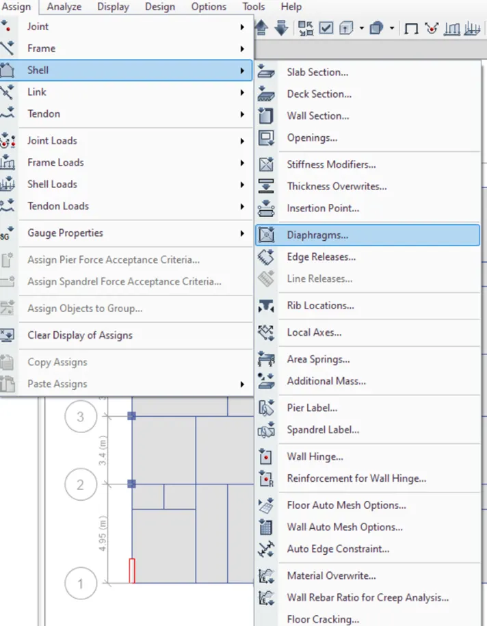
iii) Select D1 from the diaphragm assignments and click apply followed by OK.
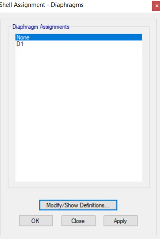
The Diaphragm D1 is applied and is as shown below.
Step 15)
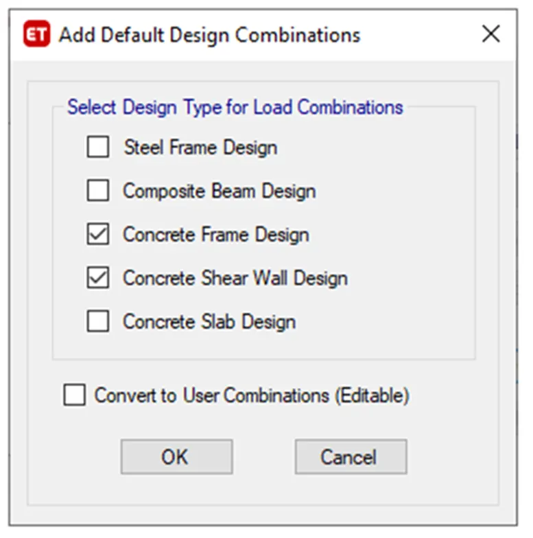
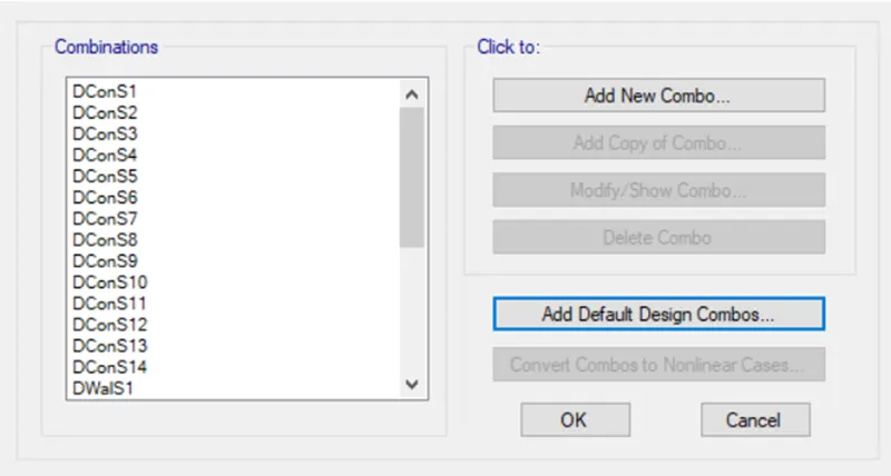
i) Now we have to add the load combinations
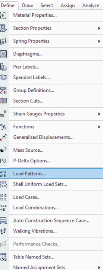
ii) Click on Add default Design Combo
Step 16)
i) Next we have to select the pier label from the shell option as shown below
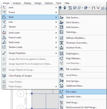
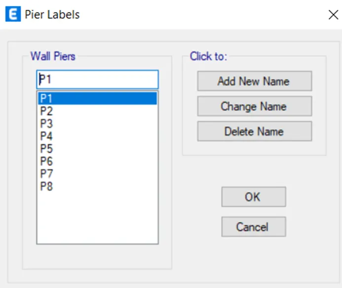
ii) Before going to the shear wall design we have to assign the names for the shear walls as P1,P2 etc .
Step 17)
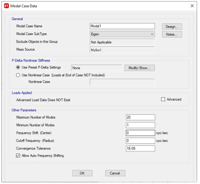
i) Now we have to create a Modal analysis
ii) For that define tab- modal cases- and select modify
iii) Enter the data’s as shown in image. Maximum number as 20.
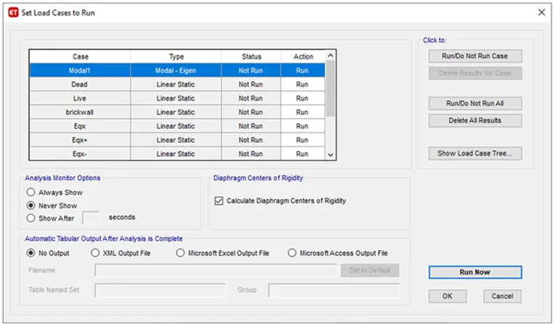
Here both spectrum analysis and equivalent lateral force are done at the same time
Step 18)
i) New function was defined as per the IS 1893 for response spectrum analysis.
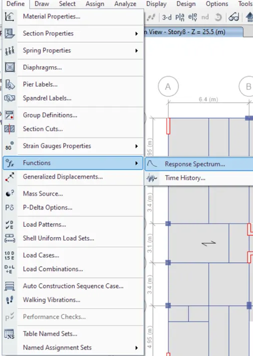
ii) After selecting the response spectrum the new tab is visible,
iii) In that we choose IS 1893:2016 from the "Choose function type" and click on the Modify /Show option as shown below
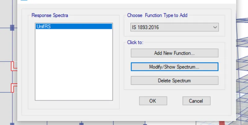
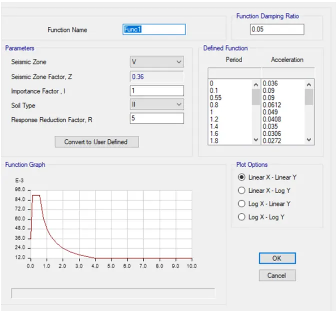
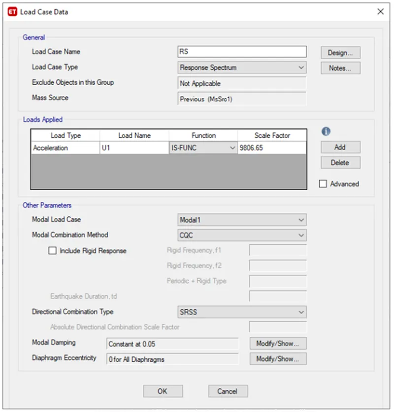
iv) Two load cases was defined for response spectrum analysis and set default scale factor initially
Step 19)
i) Now we have to check the model for errors, go to Analysis tab and select check model.
Step 20)
i) Now Run the model
ii) Click on Run Analysis
Step 20)
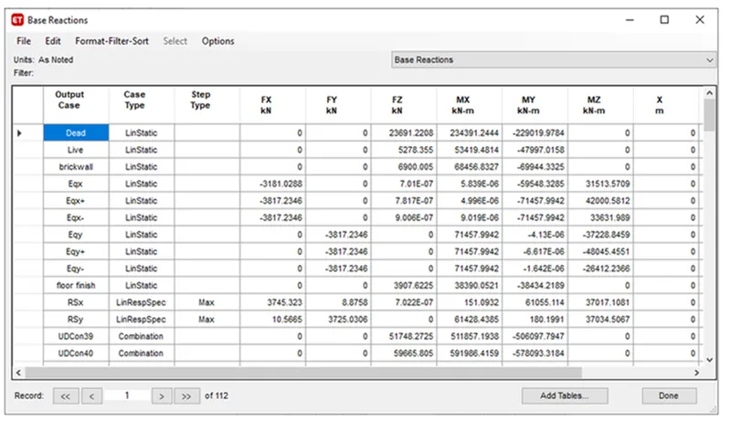
i) In order to obtain the new scale factor, go to display- show table- structural output- base shear.
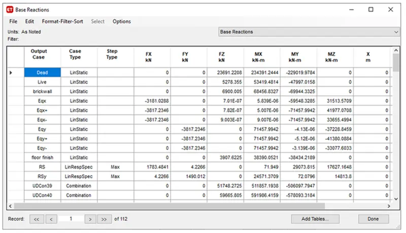
ii) As per IS 1893 design base shear should not be less than design base shear, If so then scale factor needs to be multiplied with calculated base shear by estimated base shear.
Step 21)
1) Modal Participation ratio -
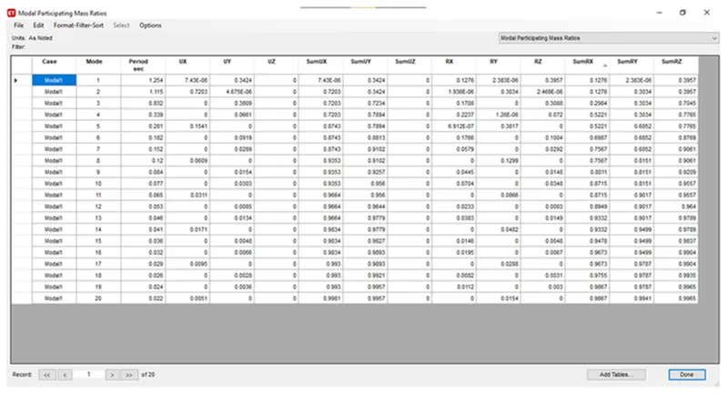
i) Modal number check for that go to Display-Show Tables-Analysis Results-Structure Output-Modal Information-Modal mass participation ratio.
ii) According to IS 1873 clause 7.1, the natural period corresponding to fundamental torsional mode of oscillation should not be greater than sum of two fundamental translational mode of oscillation (Tx+Ty>Txy)-from table 1.25+1.115=2.365>0. 832. hence no torsional irregularity.
iii) IS 1873-clause 7.1, table 6 the first three modes contribution should be more than 65% of mass participation factor in each principal plan direction. Here it is 0.738>0.65.
iv) Here Tx=1.254 and Ty=1.115, differ by 12%, hence conclude that building is regular in mode of oscillation in two principal plan direction
From modal number, maximum required is 13 number as it captures more than 90% of mass in all 6 degrees of freedom.
Step 22)
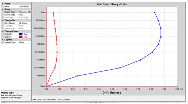
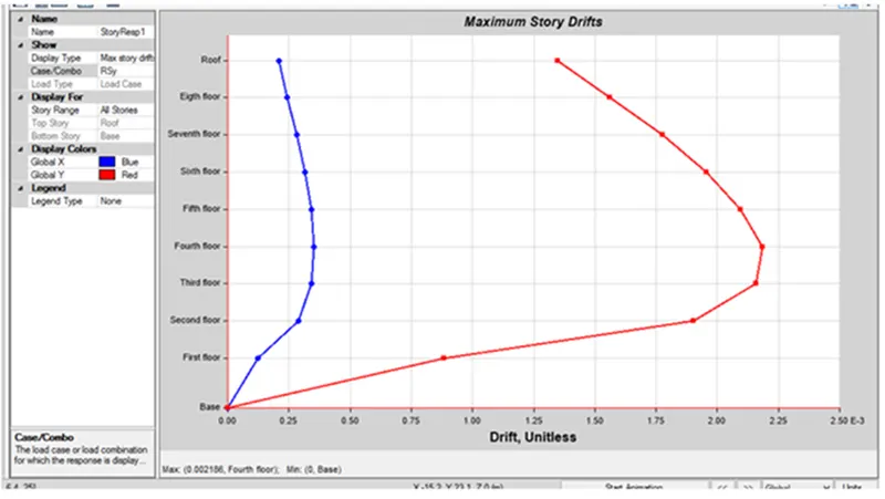
2) Storey response plot:
ii) For this go to Display-Story Response Plot- Maximum Storey drift
iii) Here storey response for maximum storey drift is less than 0.004 for both X and Y
3) Base Shear Checking:
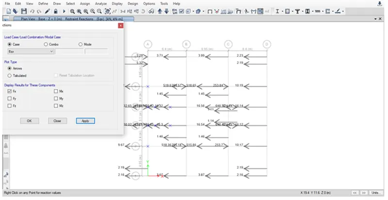
i) click on Load Display >Load Type as Eqx > Show Fx load.
ii) From code- shear wall shoud should take at least 80% of the load.
iii) In order to find the percentage,
3174/3800-83.5%>80%, provided shear wall is sufficient in x-direction.
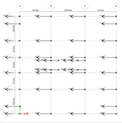
iv) 3181/3800=83% which is greater than 80% so the shear wall provided in Y direction is sufficient.
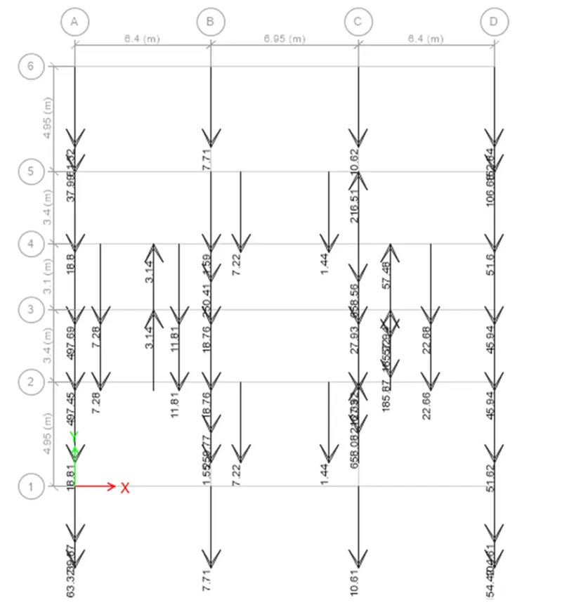
4) Check for Columns under tension:
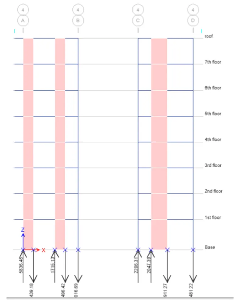
i) Under loading conditions 4b and 4d are found to be under tension.
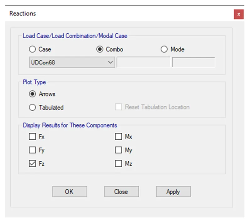
5) Check for aspect ratio for both column and shear wall.
1) Column -
i) The aspect ratio should be less than 0.4.(aspect ratio=force/cross section area*fck).
ii) Considering first load combination(1.5DL),force 1580kN.
iii) Aspect ratio=1580*1000/400*600*30-0.22< 0.4, hence ok.
2) Shear wall:
i) The aspect ratio should be less than 0.28.
ii) Force is 7.22kN.
iii) Aspect ratio=7.22*1000/1200*300*25=0.08-0.28, hence ok.
RESULT -
i) The structural model of the G+7 model is designed for given architectural planning using Etabs.
ii) Frame model which satisfies both code provision are analysed.
iii) Columns, shear walls and beam are provided in possible symmetrical way without much offsets.
iv) Analyses is done for modal number, base shear storey drift aspect ratio, irregularity etc.,