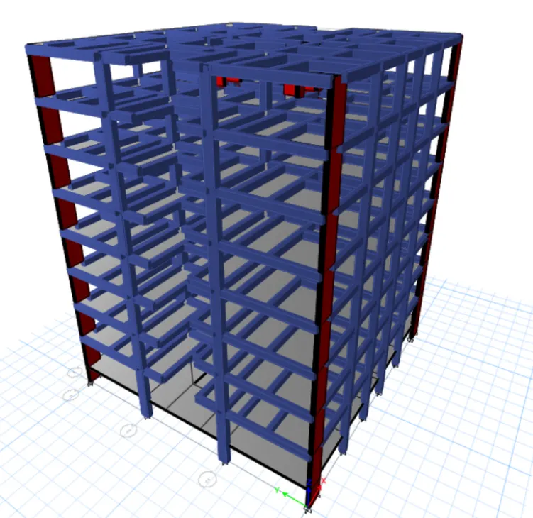
Structural Modelling using Etabs 2018
Aim
To model and analyze the G+7 residential building from given architectural drawing using the ETABS 2018
Procedure
- Open the Etabs software click on new then choose model information
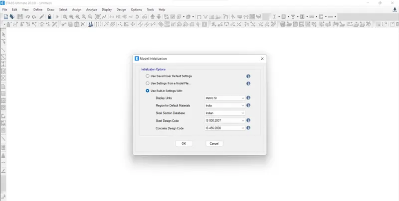
- Click on custom grid spacking select Edit grid type
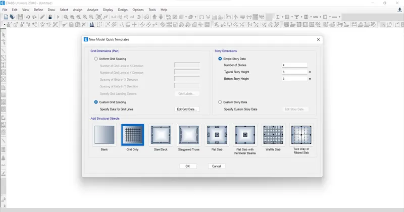
- Give X and Y grid data

Then screen will appear
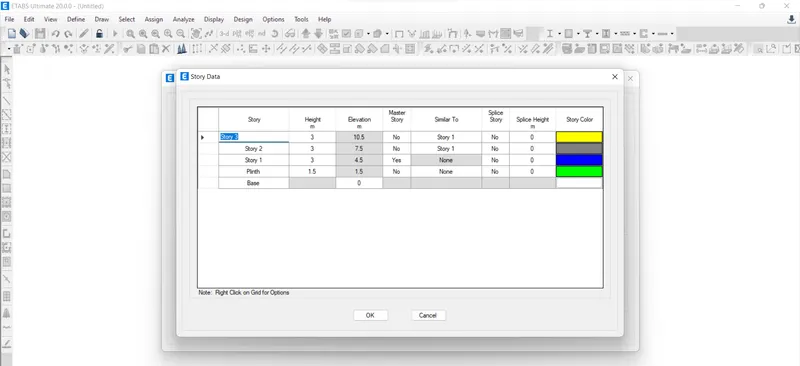
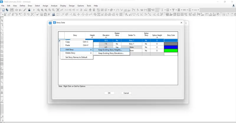
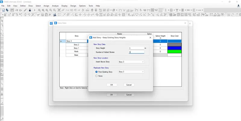
Add story height 3m
Number of added stories as 4
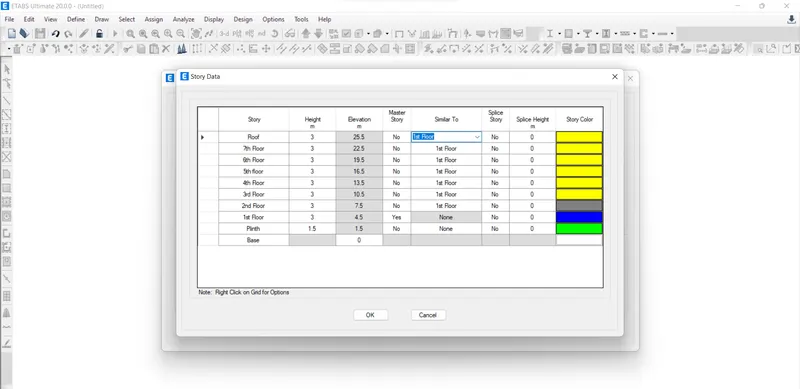
Successfully & story is created and crate all storey similar to 1st Floor
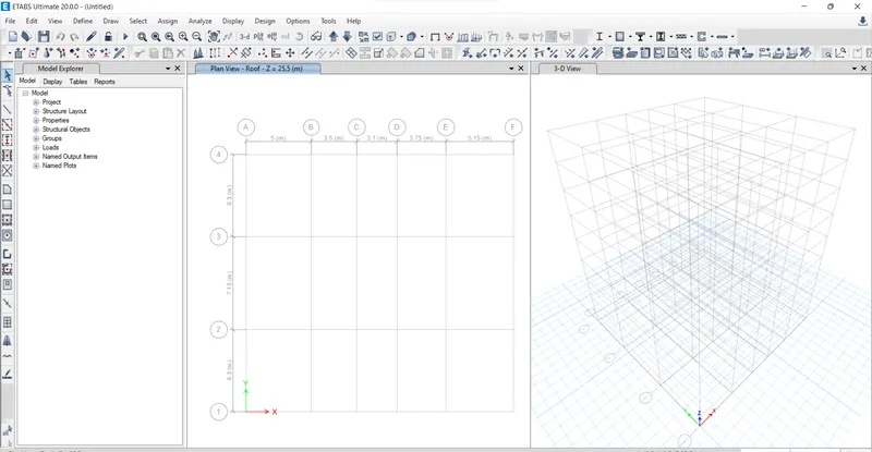
Go to define and Select material properties
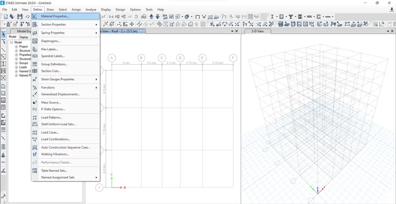
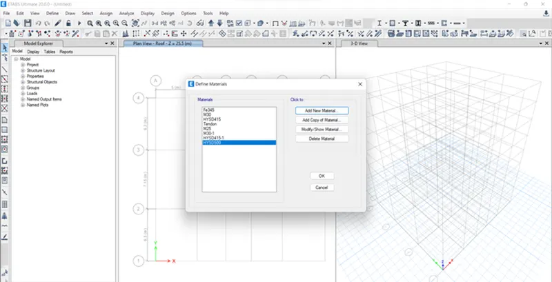
Then define material will display add material from window give all detils
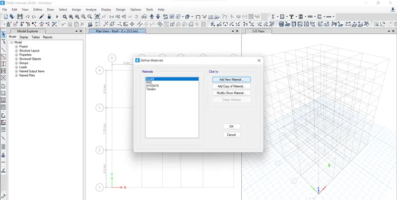
Then define material will display add material from window give all detils
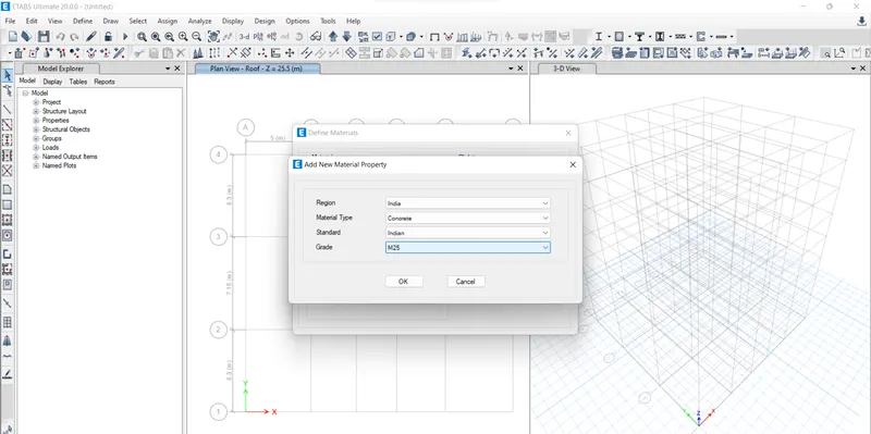
- now need to add material type as concrete and grade M25 and check material property data
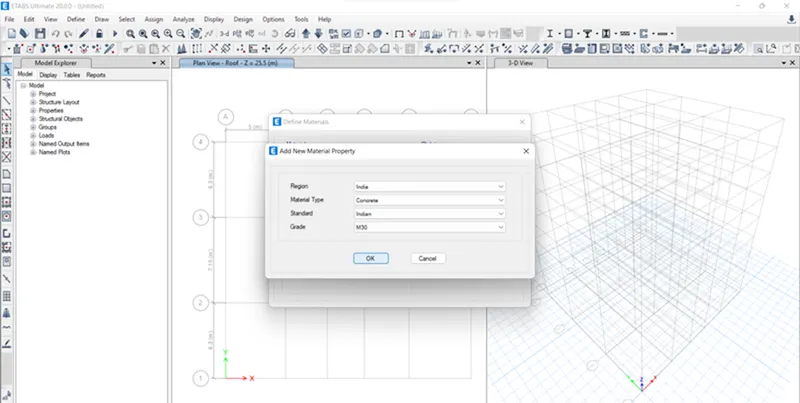
- now need to add material type as concrete and grade M30 and check material property data
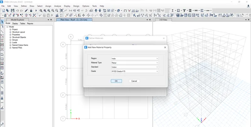
- now need to add material type as rebar and grade HYSD 415 and check material property data
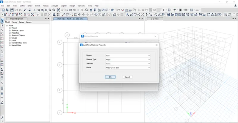
- now need to add material type as rebar and grade HYSD 500 and check material property data
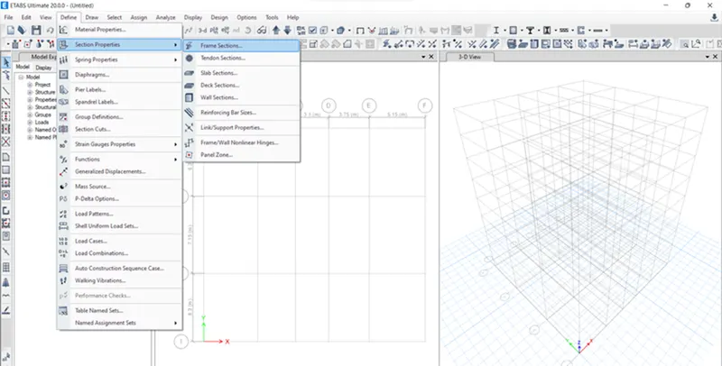
Go to define click on section property select frame section add new proerty in frame property
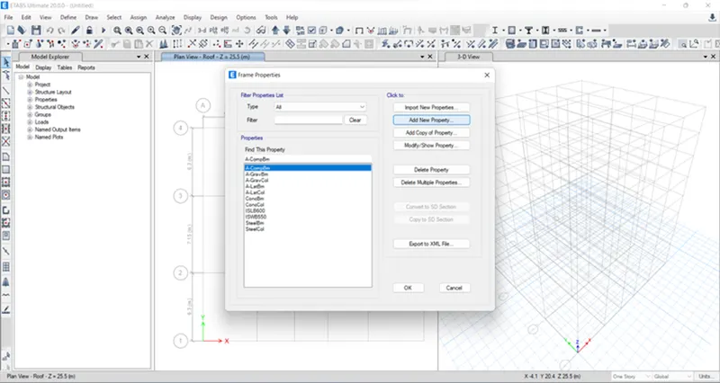
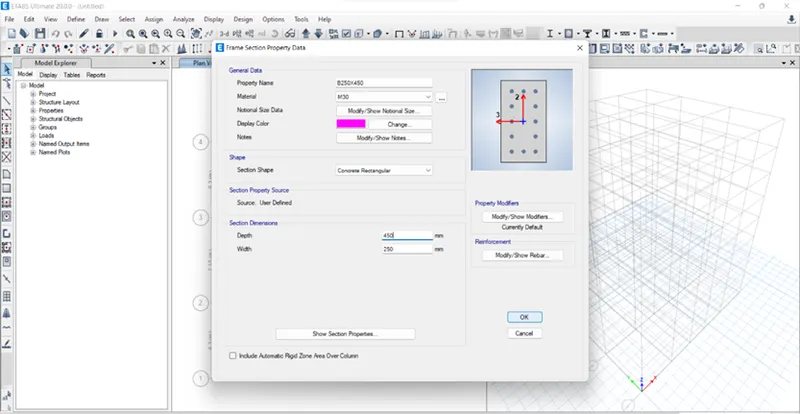
- Create new property as beam &input value 250x450 and select modify /show rebar in reiforcement option Select
- M3 design only for beam Seect rebar as HYSD 415
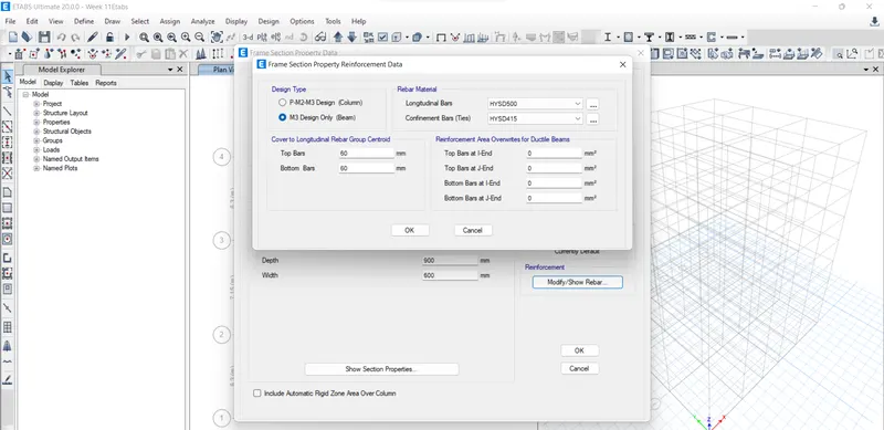
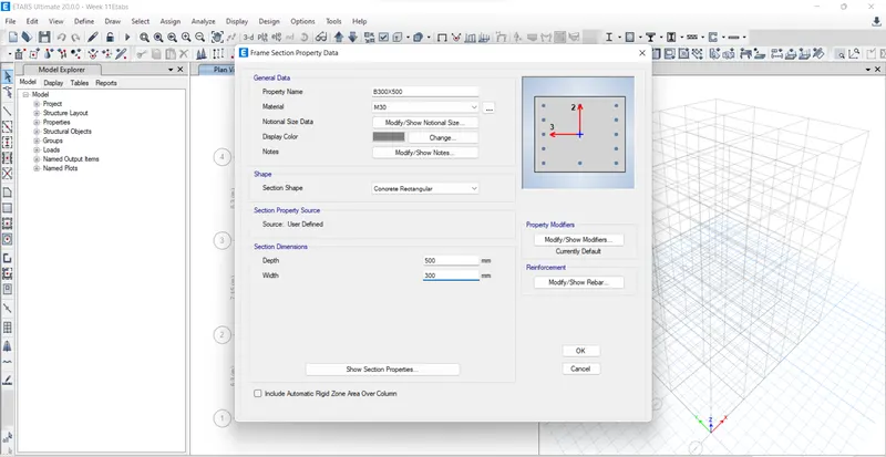
- Create new property as beam &input value 300X500 and select modify /show rebar in reiforcement option Select
- M3 design only for beam Seect rebar as HYSD 415
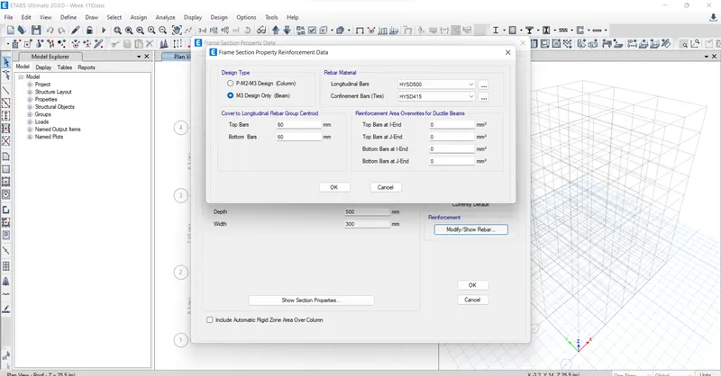
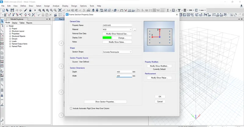
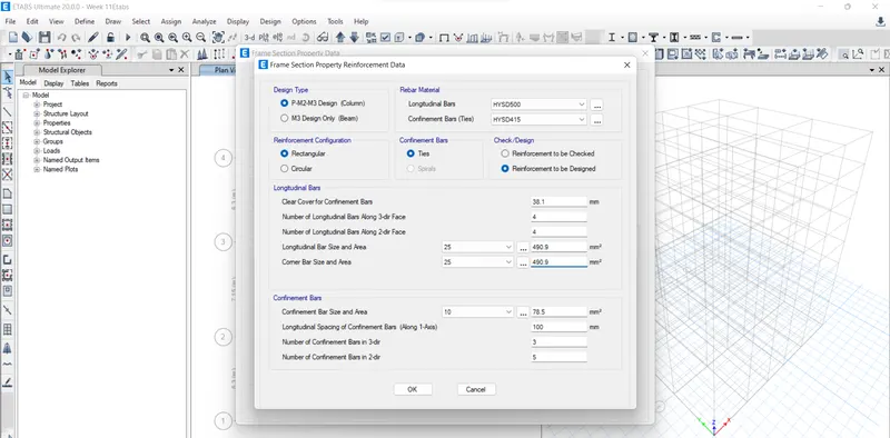
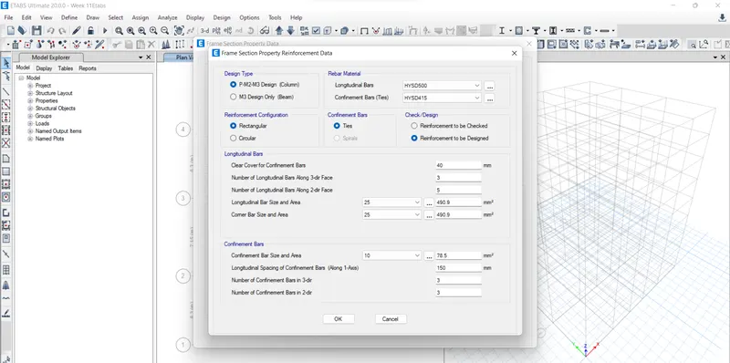
- Create new property as column and value as 400X400 and click on modify rebar in reinforcement option select P-M2-M3 design select rebar and click ok
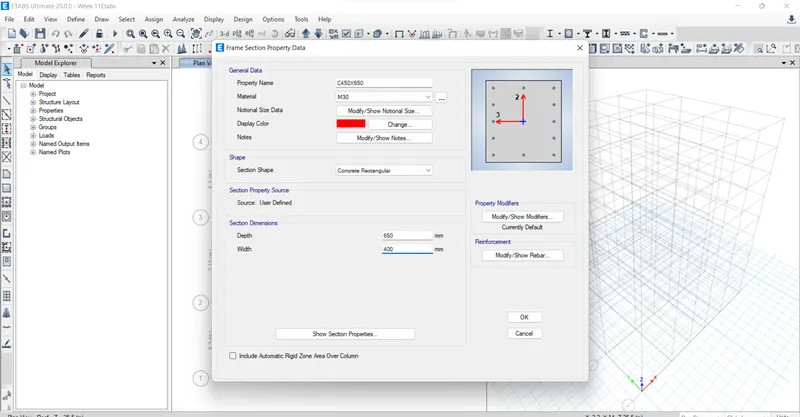
- Create new property as column and value as 400X650 and click on modify rebar in reinforcement option select P-M2-M3 design select rebar and click ok
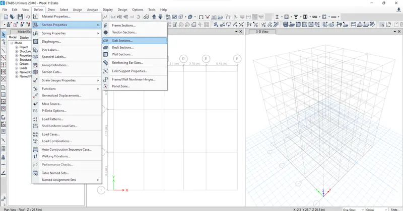
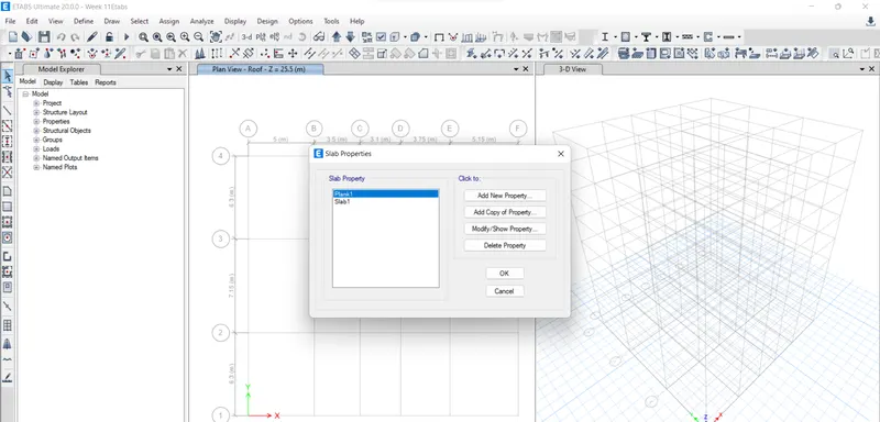
- Go to define select section property click on slab thickness
- Using membrane property slab size as 125mm it helps to consider only slab weight and floor wt in analysis of structure while no stiffness component of flange advantages are consider during calculation
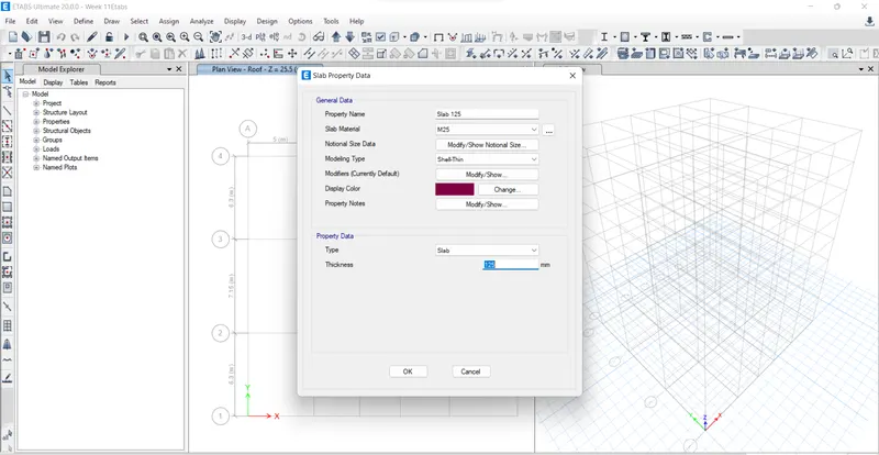
- Using membrane property slab size as 200mm it helps to consider only slab weight and floor wt in analysis of structure while no stiffness component of flange advantages are consider during calculation
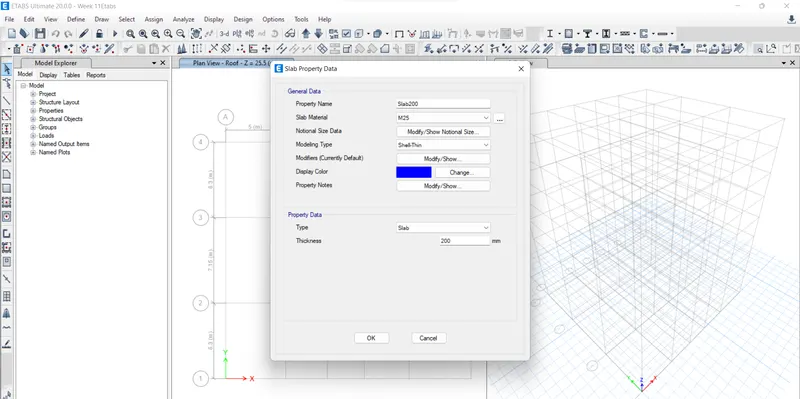
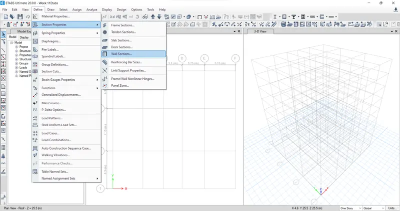
- Go to define click on section property and select wall section
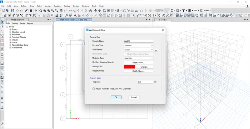
- Now add wall thickness as 250mm material-M25
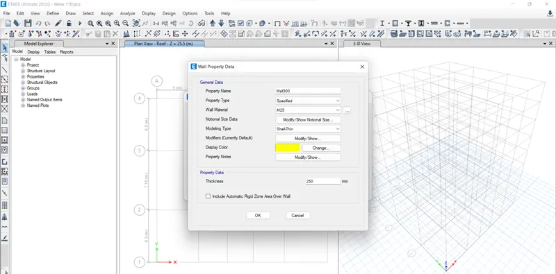
- Now add wall thickness as 300mm material-M25
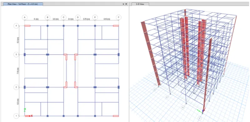
- Now draw column 400X400 mm at intersection of horizontal and vertical grid aand beams with quick draw column keeping all the stories on
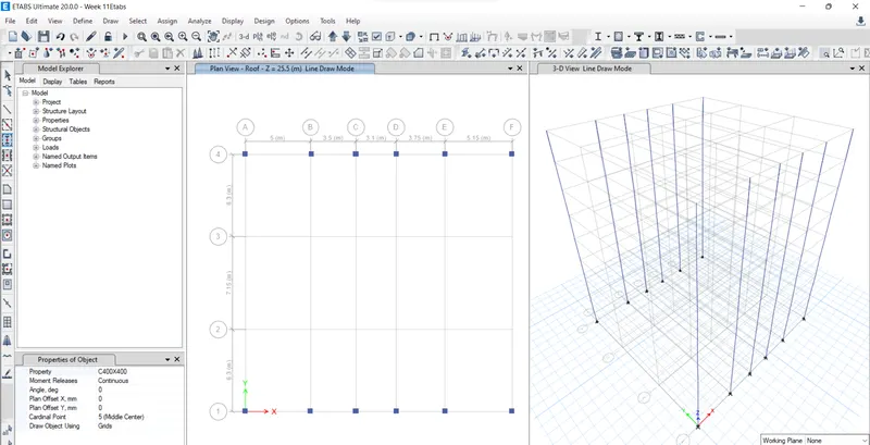
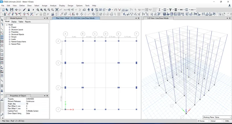
- Now draw column size of size 450X650mm at intersection of H and V grid beams and quick draw column keeping all stories on
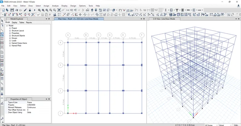
- Now drawn beam of size 250X450mm at intersection of H and V grid and beams with quick drawn beam for all stories
- Next have to drawn secondary beams
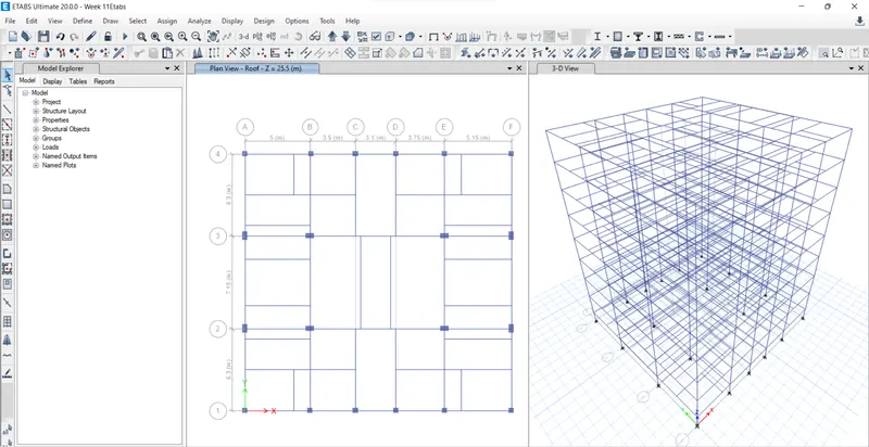
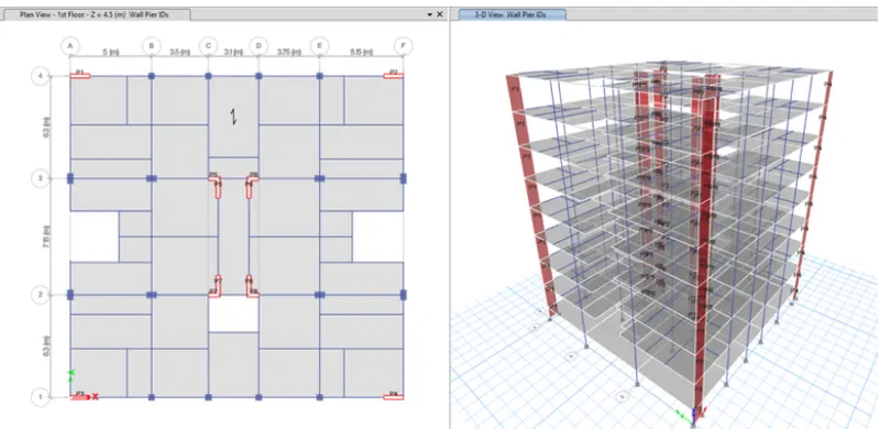
- Add shear wall required to location in longitudinal building
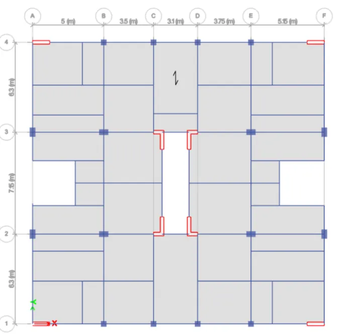
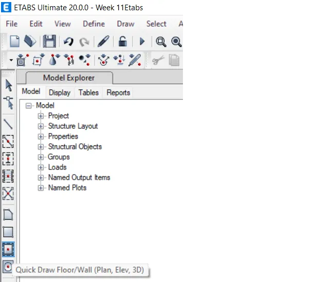
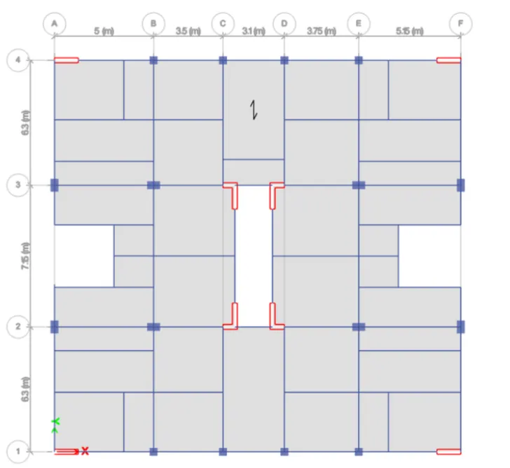
- Now draw slab as 125mm thickness
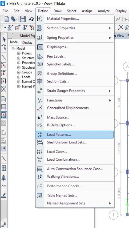
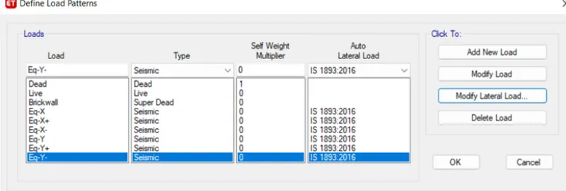
- Go to define click on load pattern Define load like DL, LL, brick load , earthquake load in X and Y direction and give iS code
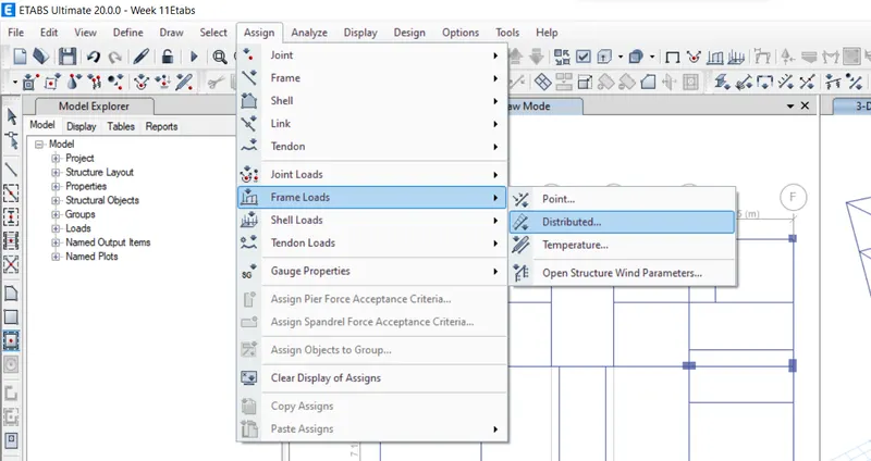
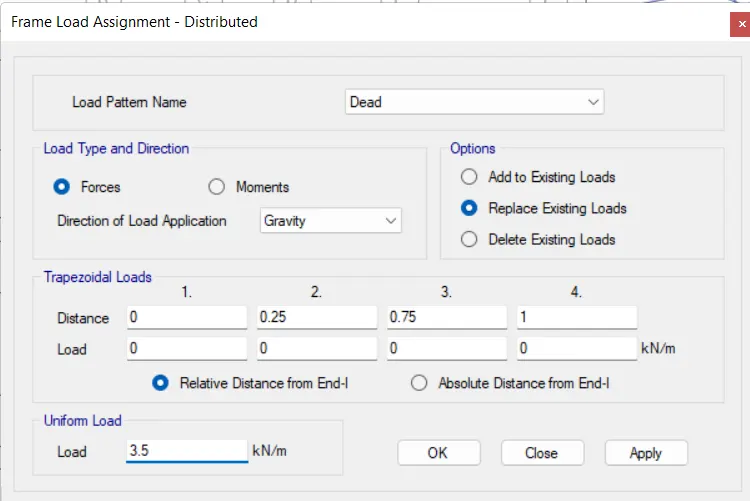
- Go to analyze click on frame load select distributed
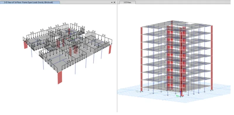
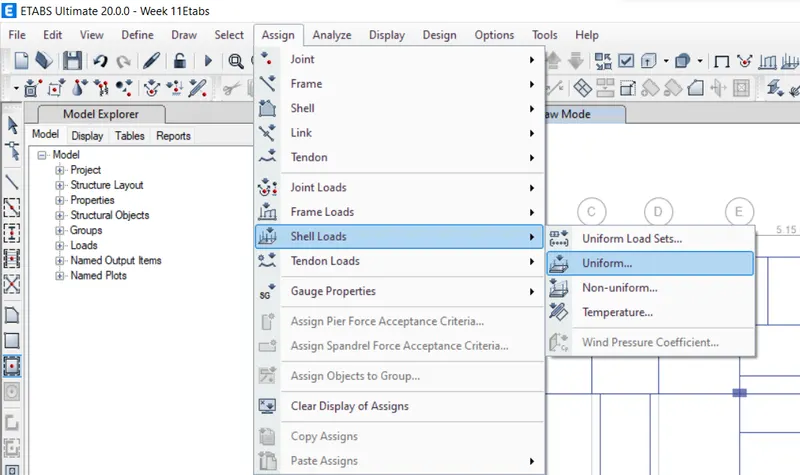
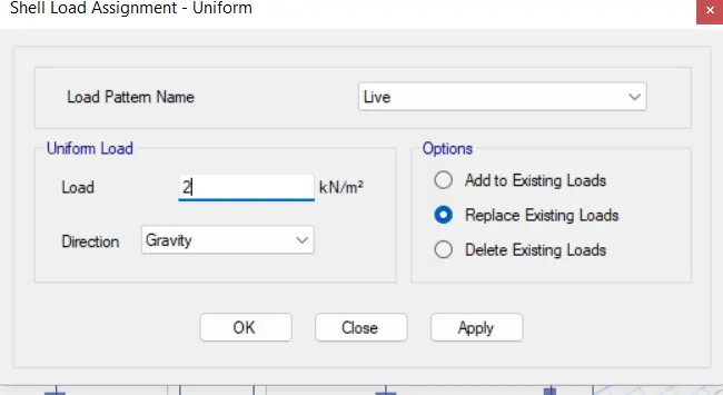
- Go to assign click on shell load select uniform option
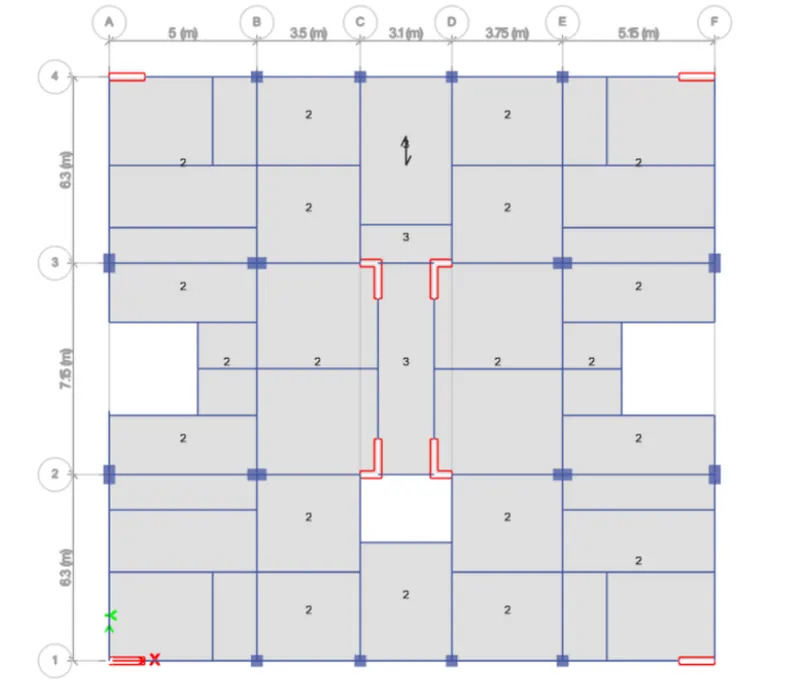
- Apply 3KN/m^2 LL forr staircase verandah and liftcore area
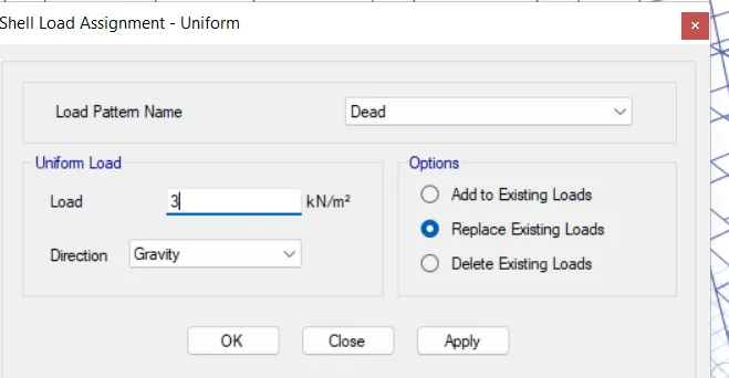
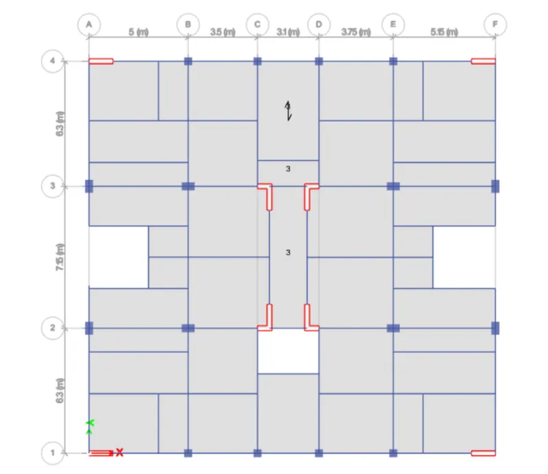
- Here apply 2KN/m^2 L for rest of portion in slabs
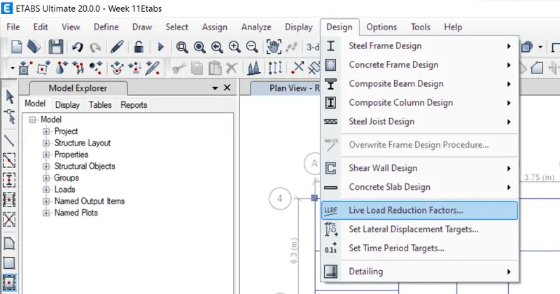
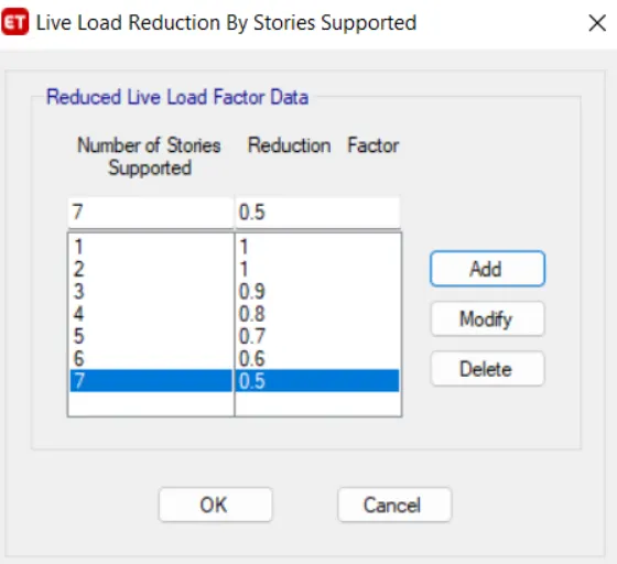
- Go to design click on LL reduction factor now add reduction factor as decrease of 10% from 1st to &th floor
- G0 to desine select mars source
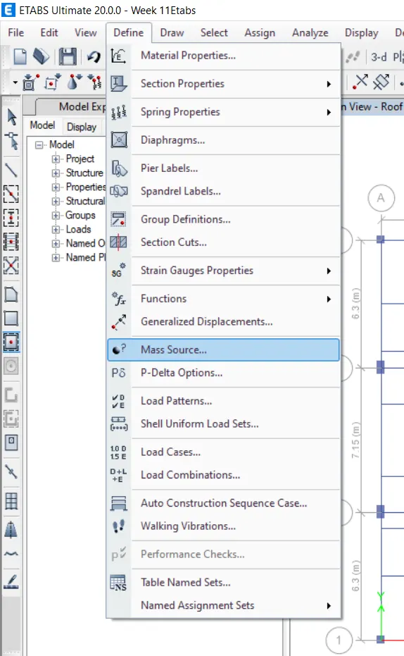
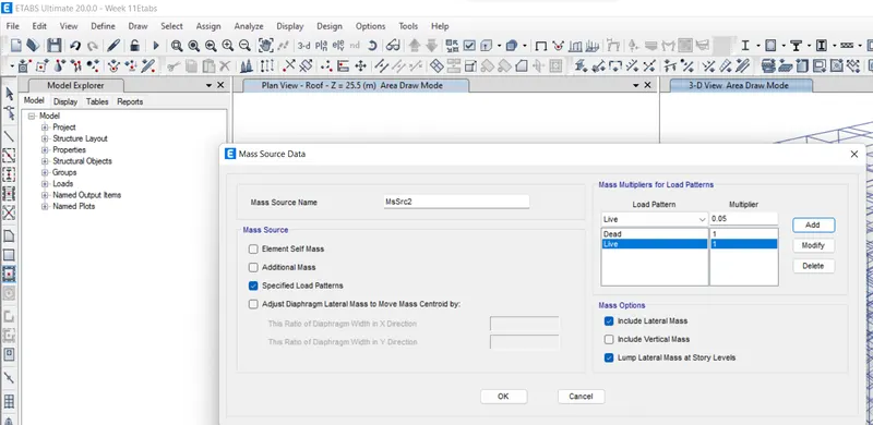
- Go to define click on load cases
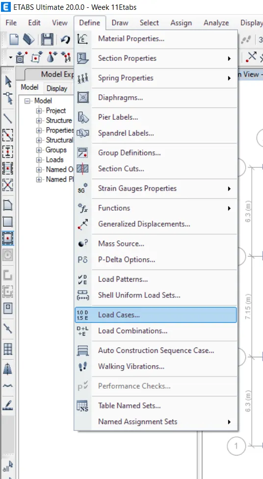
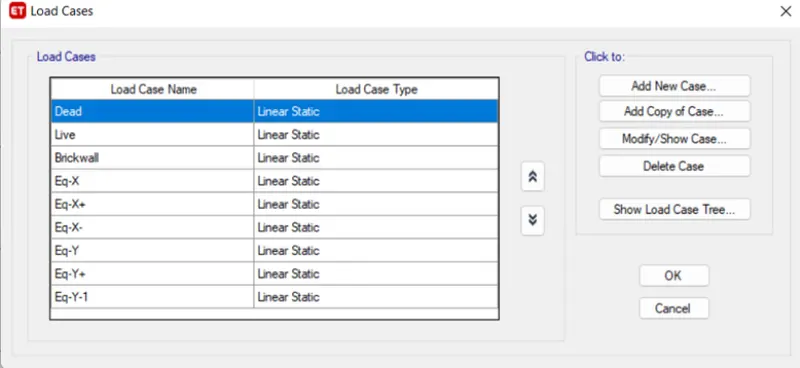
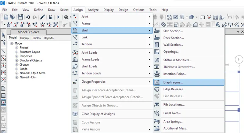
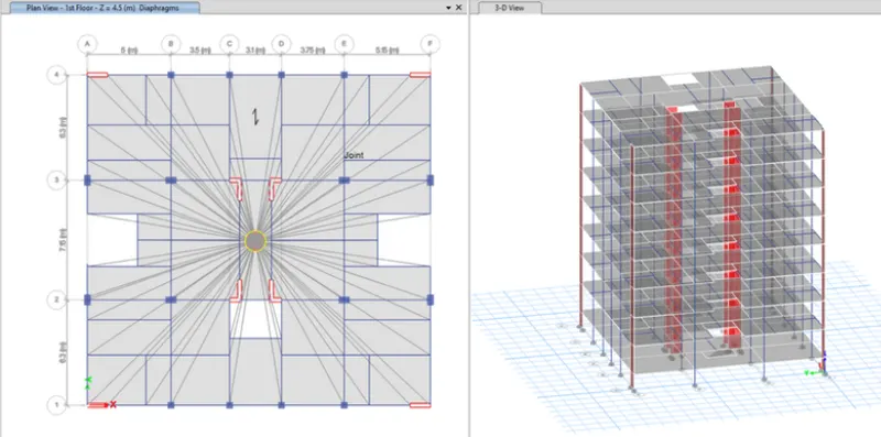
- Now create diaphragm by going to assign tab and select daiphagm
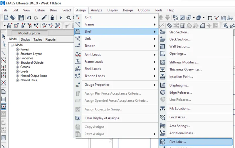
- Next go to assign click on shell select pier lable
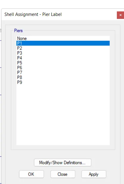
- We have assign names for shear wall
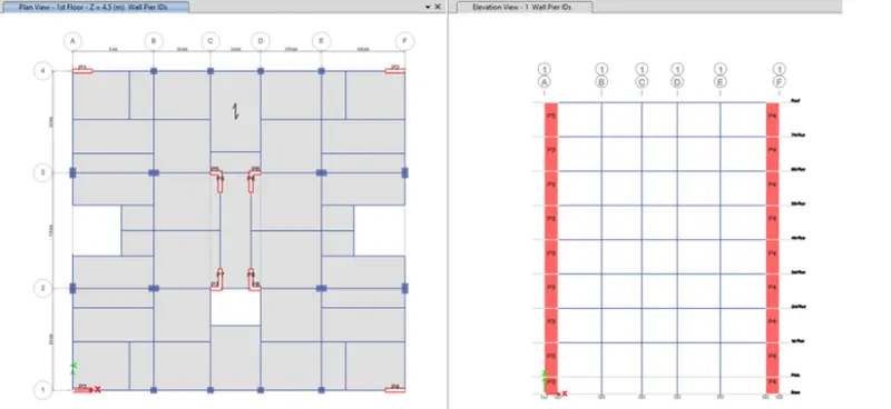
- Go to define click on load combinations select add default design combo select concrete frame
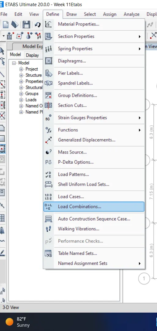
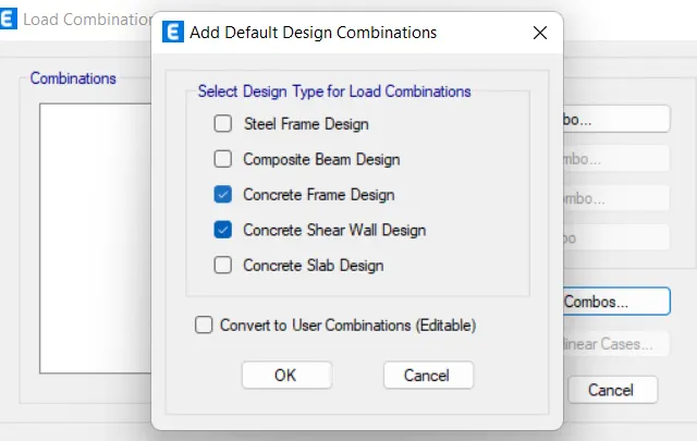
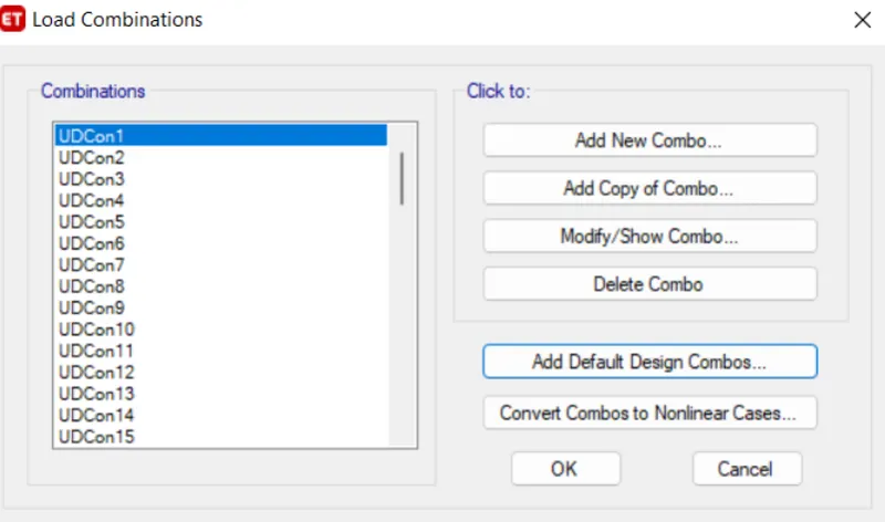
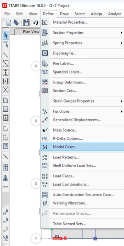
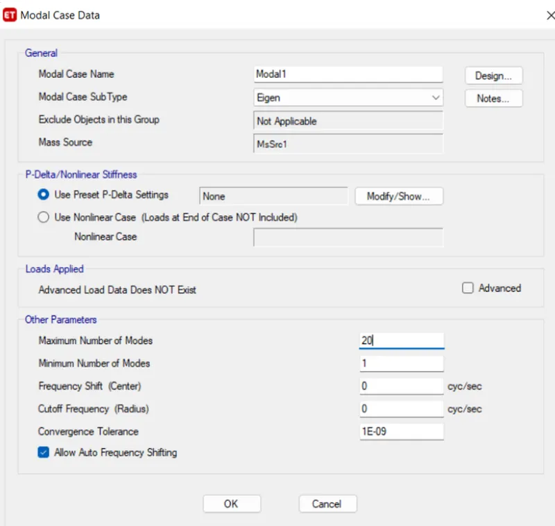
- Go to define click on modal cases give the odeal case name and number of modes
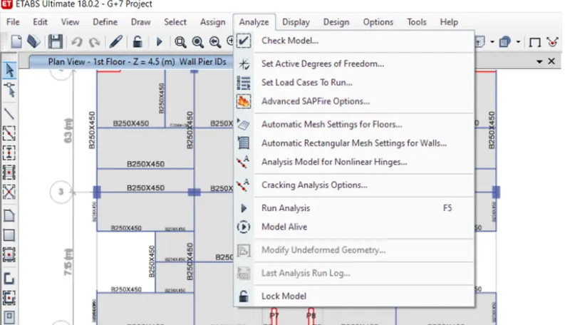
Next we need to check the modal
- After model is checked it show no warning
- Go to define click on function select response spectrum
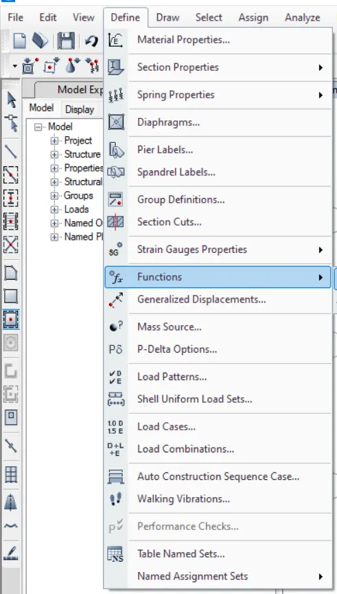
- Choose IS 1893:2016 from choose fun type and click on modify spectrum option
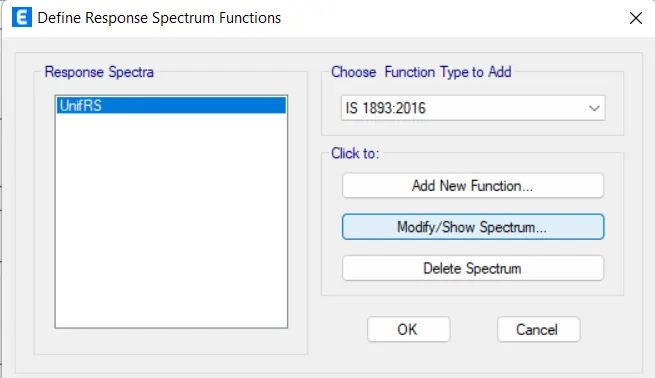
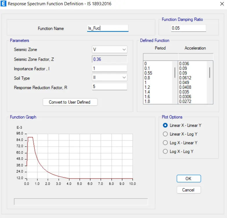
- Go to define click on load cases
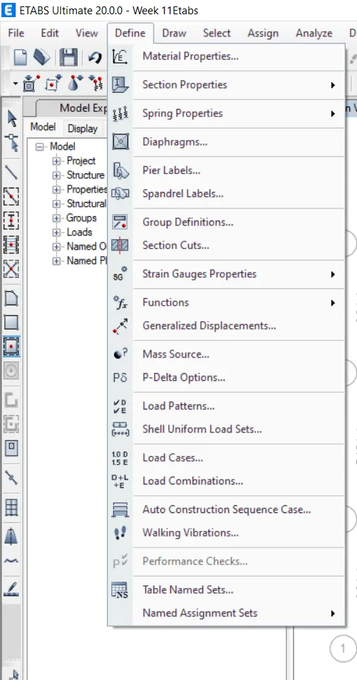
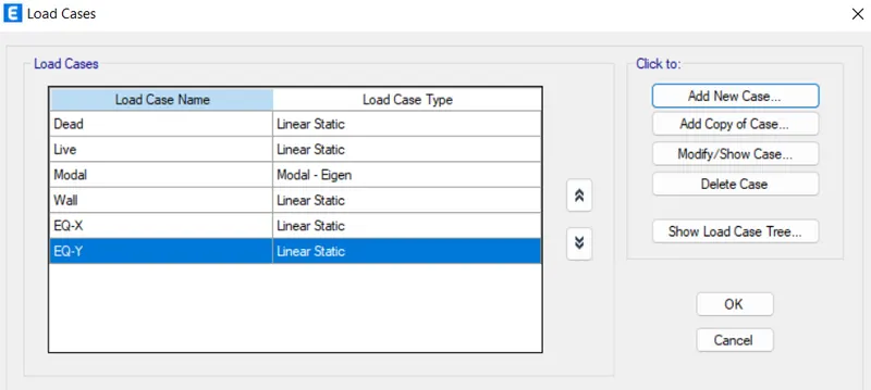
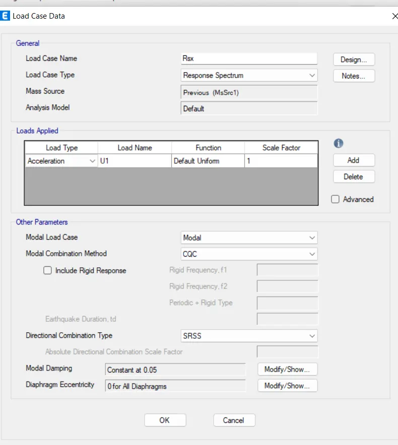
- Analyses the modal using analysis option
- Then table will display click on structure output and select base reaction
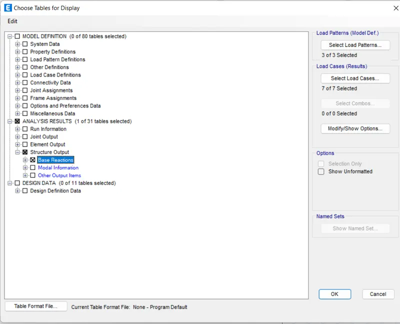
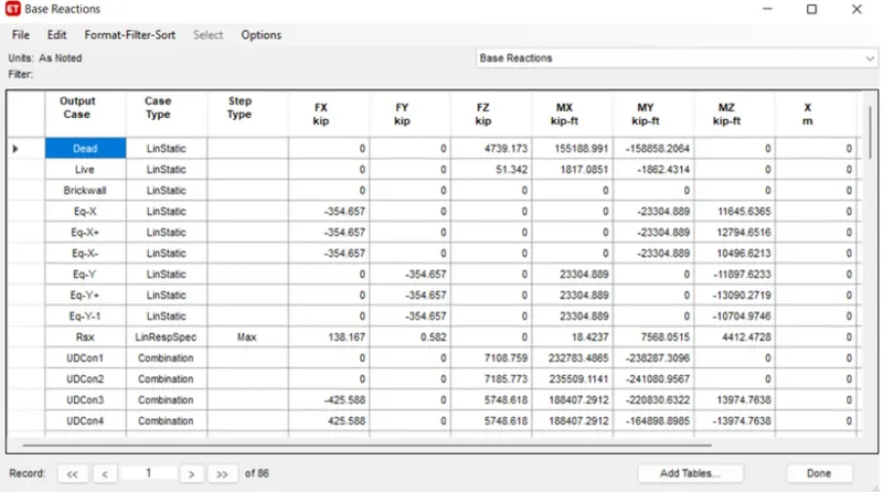
- Click on display then table appear on screen click on structure output , model information select modal periods and frequencies
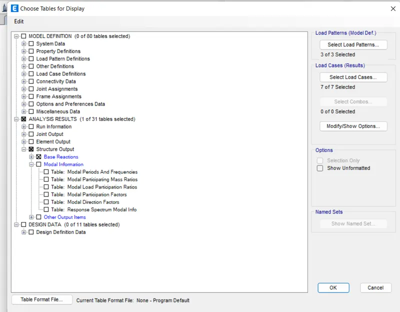
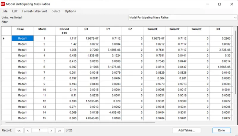
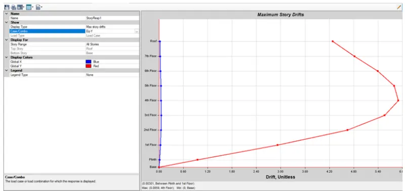
- Select story response plot on display option
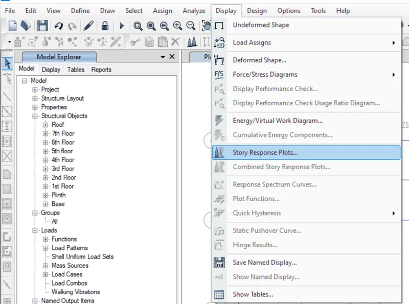
- Story response for max story drifts for X and Y direction
X Direction
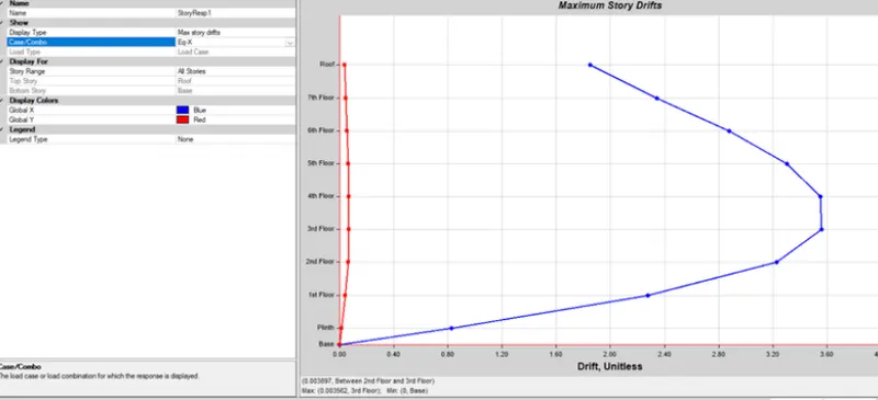
Y Direction
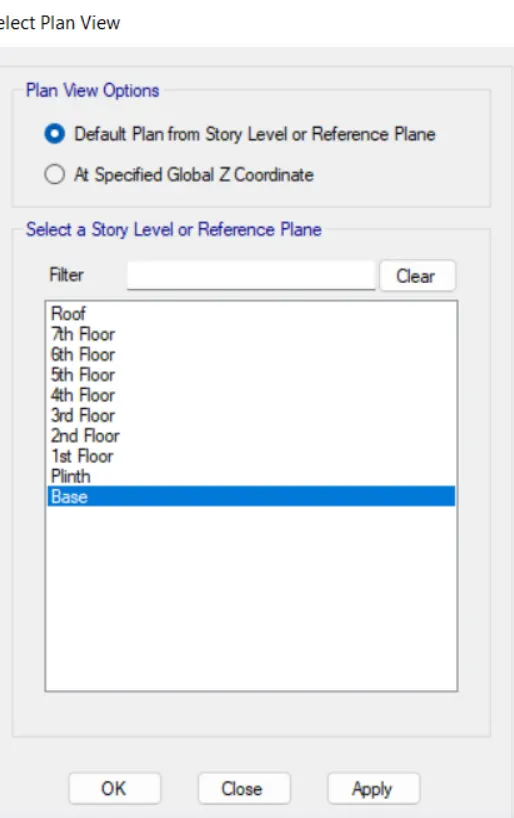
- Next open base floor in plan view
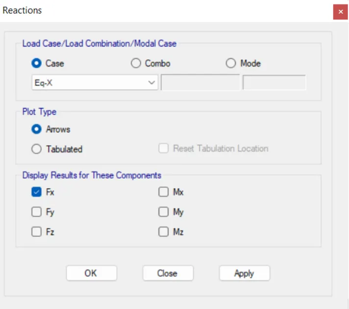
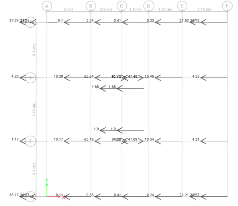
- We have to open reaction tab, we select earthquake load towards X direction in load cases
- When we divide base shear taken up by shear wall divided by total base shear of building will get % of shear forces taken by shear wall
Result
Modeled and analyzed G+7 residential plan from given archotectural drawing using ETABS 2018