Structural Modelling using Etabs 2018
Aim:
To model an apartment with all seismic consideration, based on given architectural input and to know how to check the seismic performance of an apartment using ETABS
Introduction:
To model and analyse the G+7 residential building with the given architectural drawing using ETABS
Objectives:
Data required for ETABS analysis-
- Pinned support, base + 9 story (ground to terrace) + 1 mumty
- Column 300x600mm & 300X750, beam 300x450mm, slab 150mm thick, shear wall 300mm thick
- Live load 2kN/m2, floor finish 1.5kN/m2, wall load 3.5kN/m, water tank 20KL over mumty equivalent to 200KN overall load
Conceptual design consideration before analysis-
- Re-entrant and cut-out check and modification (compromise)
- Vertical irregularity (soft story)
- Planar irregularity (looks symmetrical)
- 2% shear wall area with respect to build area (8m2)
- Stiffness modifier for column, beam & shear wall (0.35 for beam, 0.7 for vertical)
Key point to remember while modelling-
- No slab, no wall load in ground floor
- Proper end releases in beams as per engineer intent
- No interior wall load in terrace
- Comparison of static and dynamic forces and revising the factor
Procedure:
Step 1: First we have to create a model reference in AutoCAD.
- Open the given Dwg file in the AutoCAD.
- Now using this given DWG file, create a new one. In this you have to show the repositioning and resize of the columns and the orientation. Without disturbing the parking area.
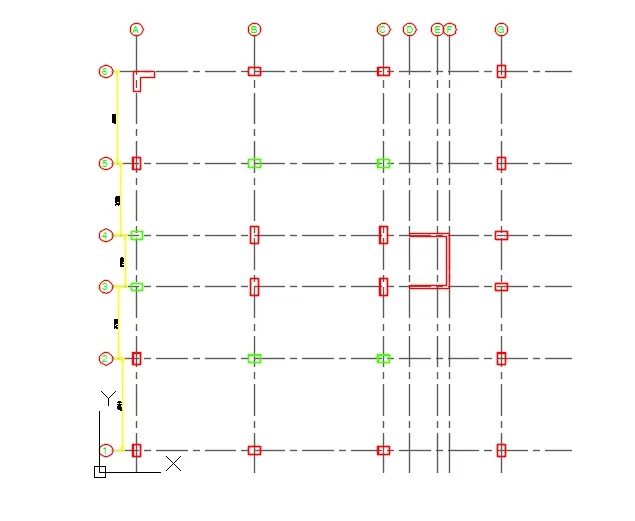
- This drawing we have created is used as a reference drawing in the ETABS.
- Now creating the grids as per the reference Drawing.
Step 1: Creating model in the ETABS
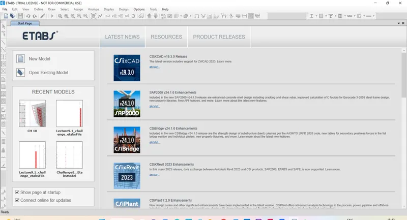
- Open the ETABS
- For creating a new model click on the New
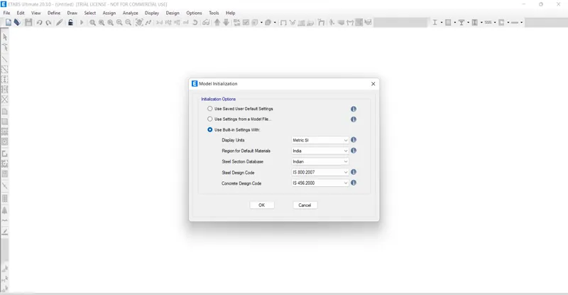
Step 2: Creating the Model Initialization.
- Do the following setting given in the image below.
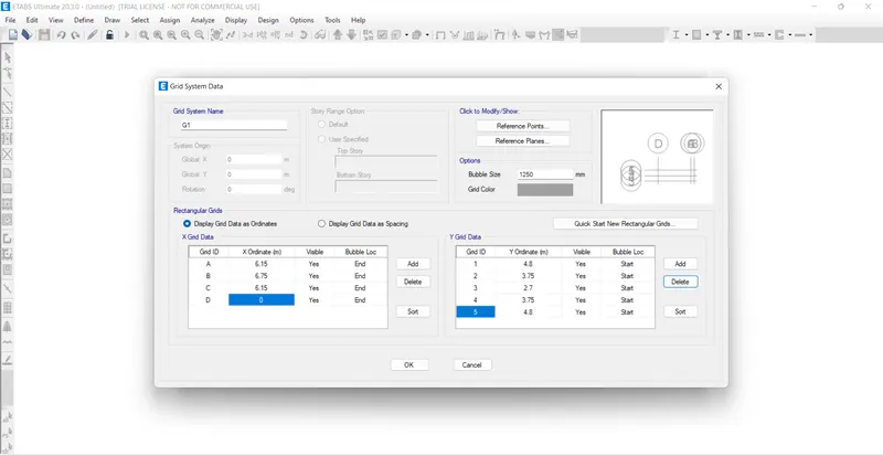
Step 3: Creating the Grids using reference drawing we have created in AutoCAD.
- After clicking on the OK in Model Initialization a new dialogue box will open.
- Select Custom Grid Spacing and click on the Edit Grid Data.
- Enter the X spacing of grids in (metre).
- Enter the Y spacing of grids in (metre).
- Adding the Storey data
Step 1: Creating the storey data
- Click on custom storey data
- Edit the requires storey given in the challenge.
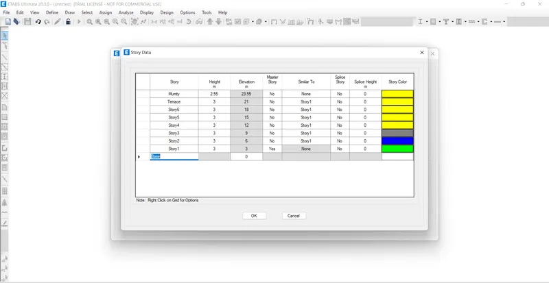
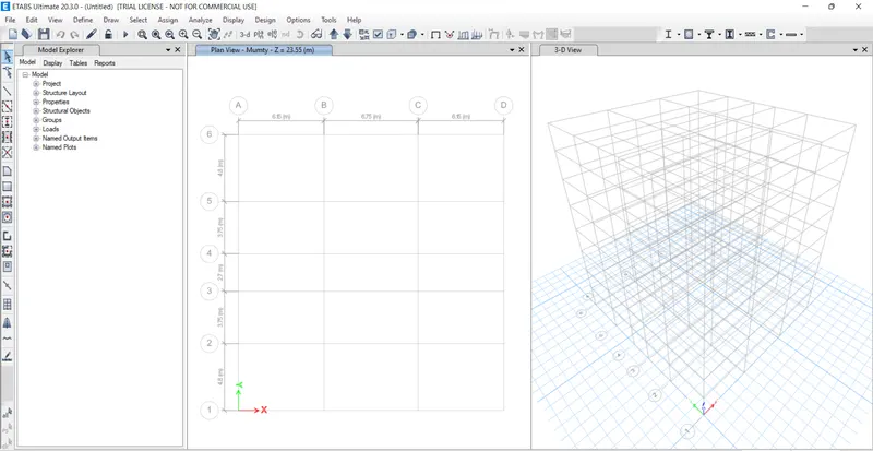
- Defining the materials for the drawing.
Step 1: First define the materials properties.
- Click on the materials properties.
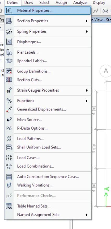
- Then a dialogue box will appear
- Click on add new
- Select Material Type Concrete and ensure Grade M30 click OK.
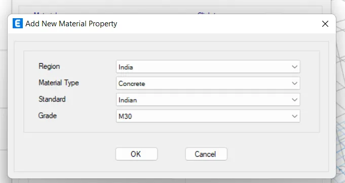
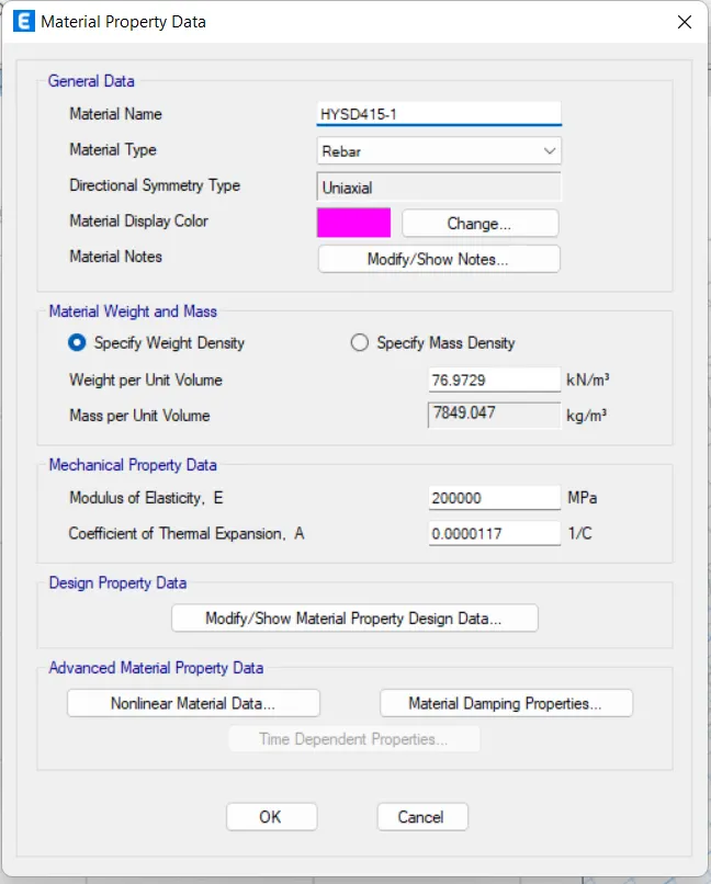
- Again, click on Add New Material
- Select Material Type Rebar and select Grade HYSD 550 & 415 click OK
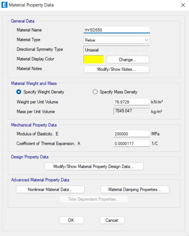
- Now we have to Add the Column, beam and shear wall.
Step 1: Adding the column
- In the Define tab, select Frame Section from Section Property.
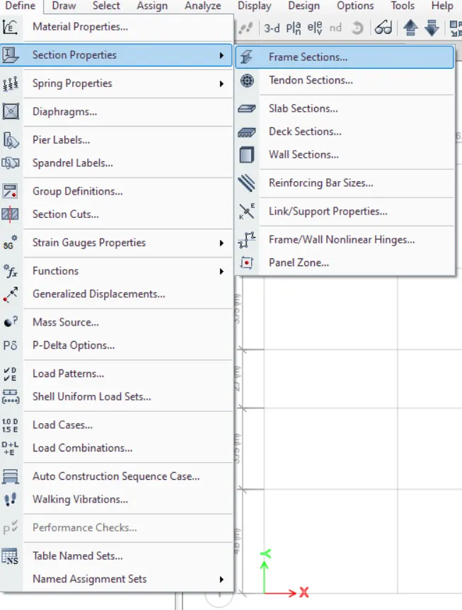
- Click on Rectangular Section for Beam from Frame Property Shape Type.
- Change the Property Name as C300X600 and Material M30
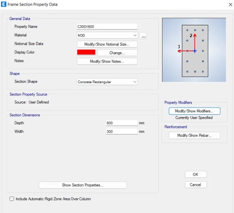
- Now click on Modify show rebars option and change the settings.
Step 2: Adding the Beam.
- Click on Rectangular Section for Column from Frame Property Shape Type.
- Change the Property Name as B300X450 and Material M30
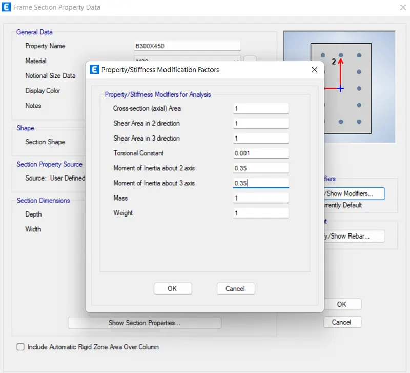
- Now click on Modify show rebars option and change the settings.
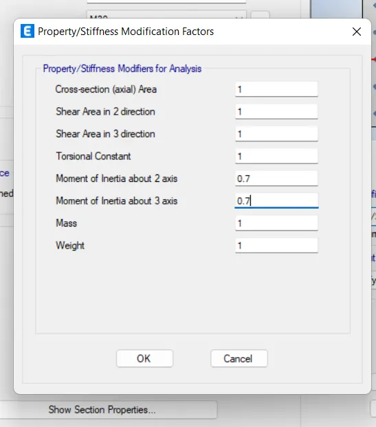
Step 3: Adding the Shear Walls.
- In the Define tab, select the wall sections.
- Then select the wall and provide the thickness as 300
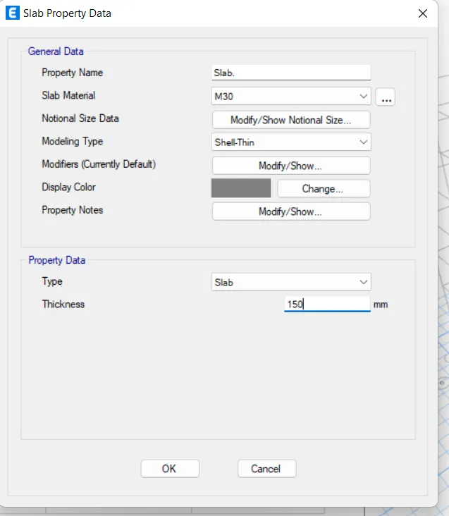
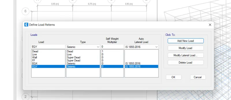
6. Adding Load pattern.
- Click on Define
- Select the load pattern from it
- Now add different load case i.e. Live, Dead, Wall and Floor finishes as Super dead type and EQX and EQY as Siesmic type
7.Now defining Mass Source.
- Click on Define then select Mass source.
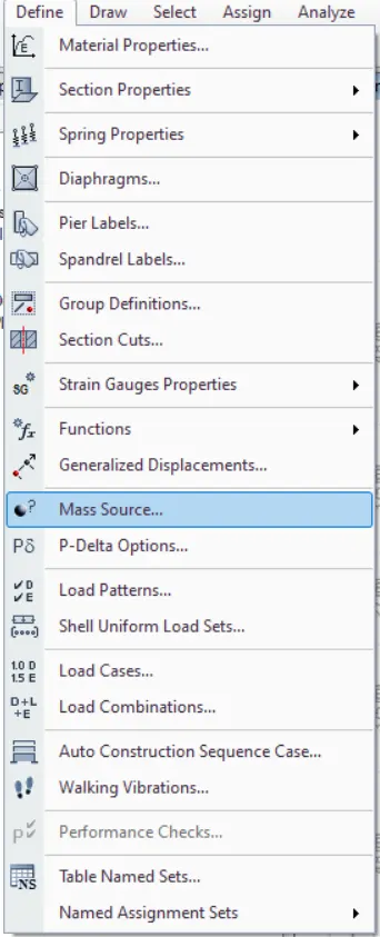
- A dialogue box will appear
- Now click on Modify
- Check mark only Specified Load Pattern
- Add wall, live and dead load,Floor finishes as shown below
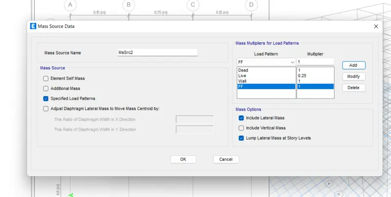
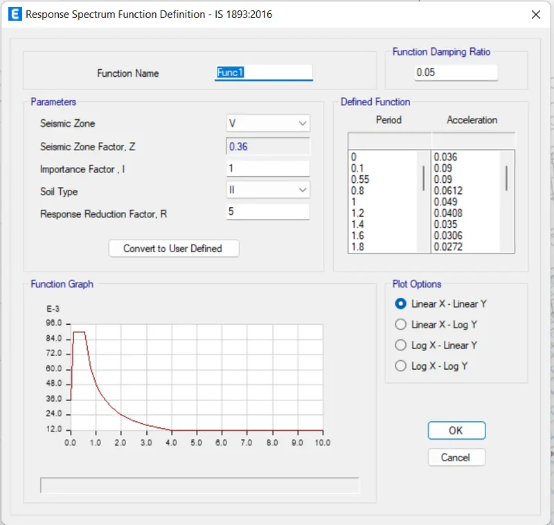
8.Checking the Response Spectrum.
- Click on define
- Then Select the Response spectrum in the function
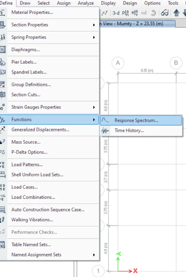
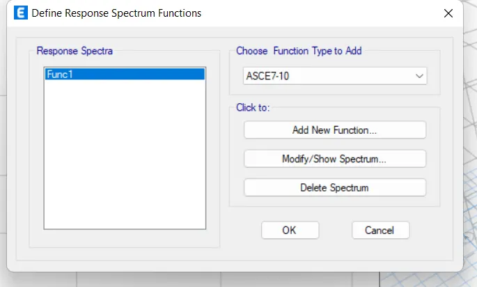
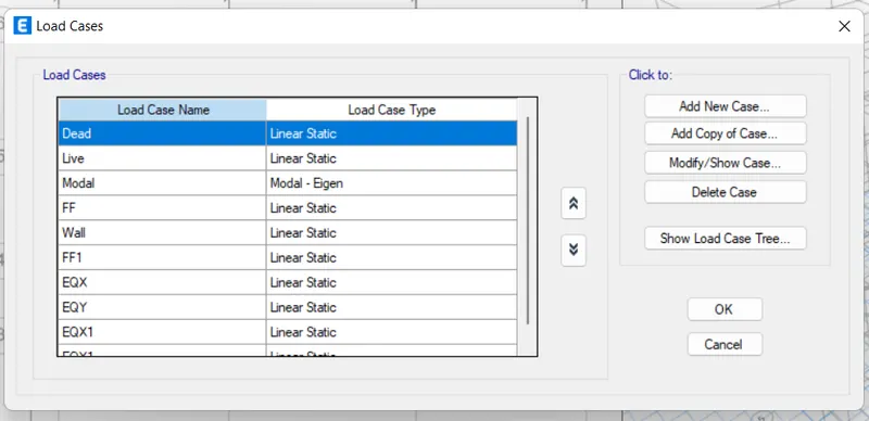
9. Checking the Load Cases.
- Click on define
- Then select the load cases.
- A dialogue box will appear which shows the Loads
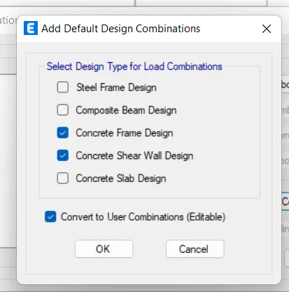
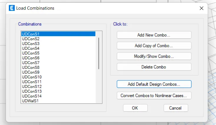
10.Now for Load Combinations.
- Click on define
- Then Click on Load combinations
- Check the follwing things shown below.
11.Now Drawing the Columns, Beams and Shear walls.
Step 1: Drawing the Shear walls
- In the left side select the wall option
- And draw the shear walls.
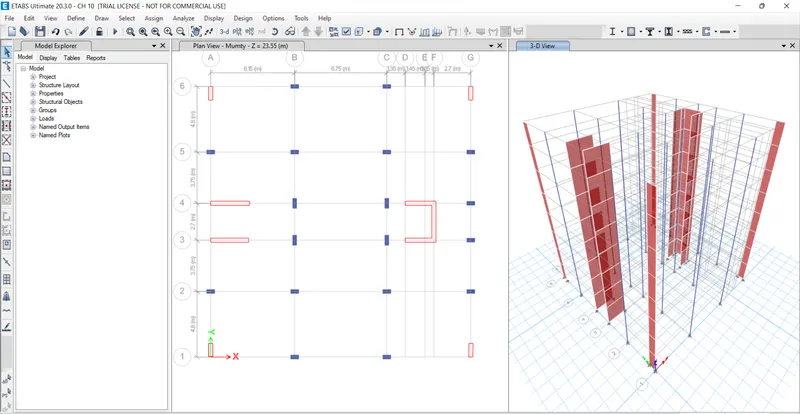
Step 2: Drawing the beams
- Draw the beams as required
Step 3: Drawing the columns
- Select the columns from the property browser.
- And draw the columns.

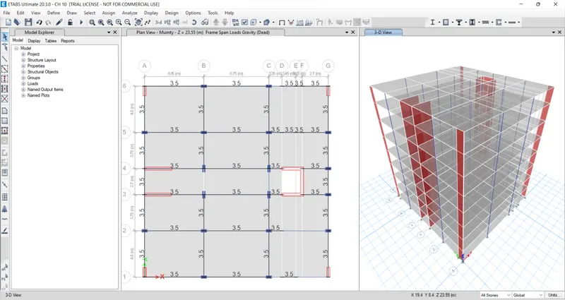
12. Assigns the Load cases.
Step 1: Applying distributed load of 3kN
- Select all the beams
- Click on Assign and then click on the Frame loads and then distribution.
- Then modify the 3kN
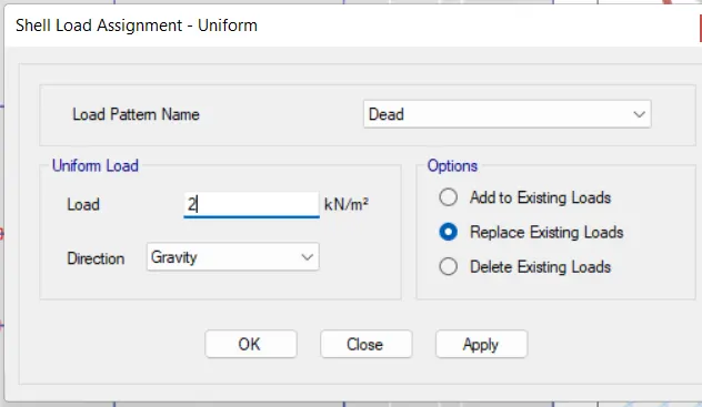
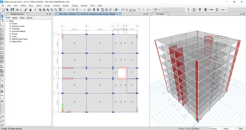
Step 2: Applying the uniform load of 2kN
- Select all the beams
- Click on Assign and then click on the Shell loads and then Uniform
- Then modify the 2kN
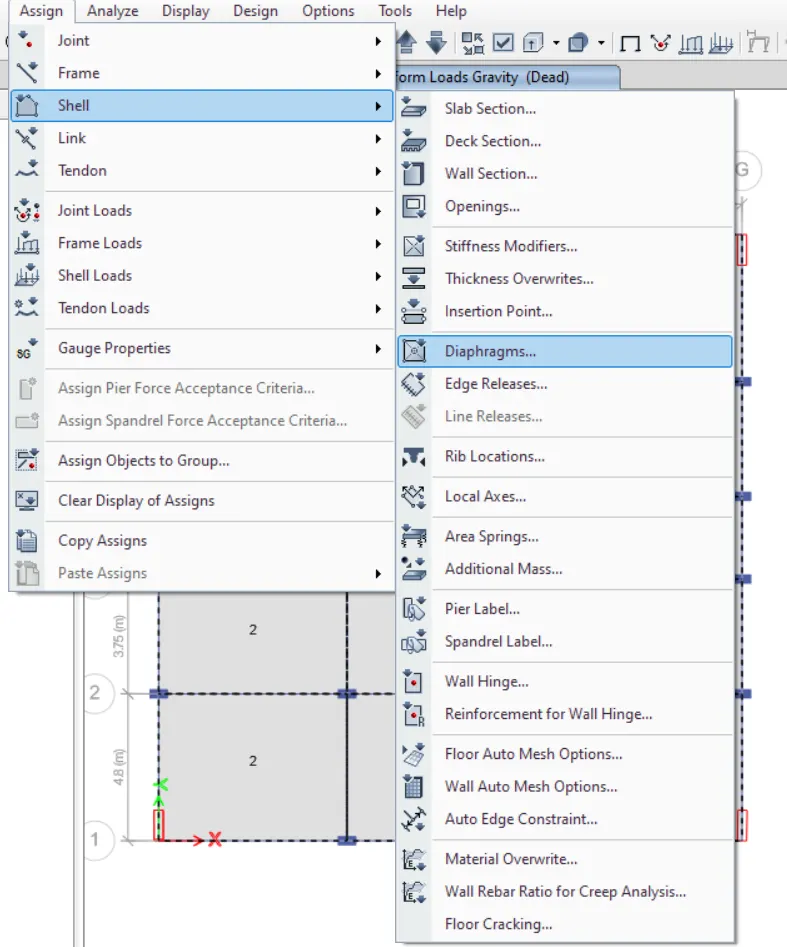
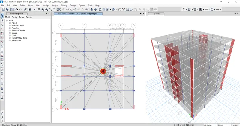
13. Now Adding Diaphragms
- Select Slab
- Assign Shell as Diaphragms
14. Assigning the base support.
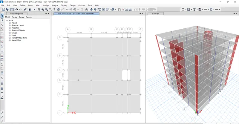
- Go to the base plan
- Select all the joitns
- Click on Assign then joints>restrian
- Select fast restrain and click ok
- All the joints are fixed
- Run the Model Analysis
- After completion of anaysis we got max. & min. deflection
- Check the result Result
- Form table checked the modal infromation and compare the result
- First two fundamental modal mass grater than the torsional mode
- Modal mass participation for first 3 modes dominates at least 65% (Achieved for X-axis only)
- Mode-1 and Mode-2 differs by 10% (Achieved)
- Principal modes be greater than Torsional mode (Achieved)
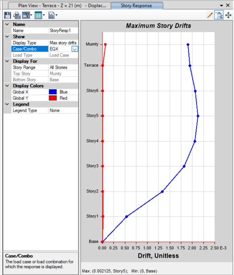
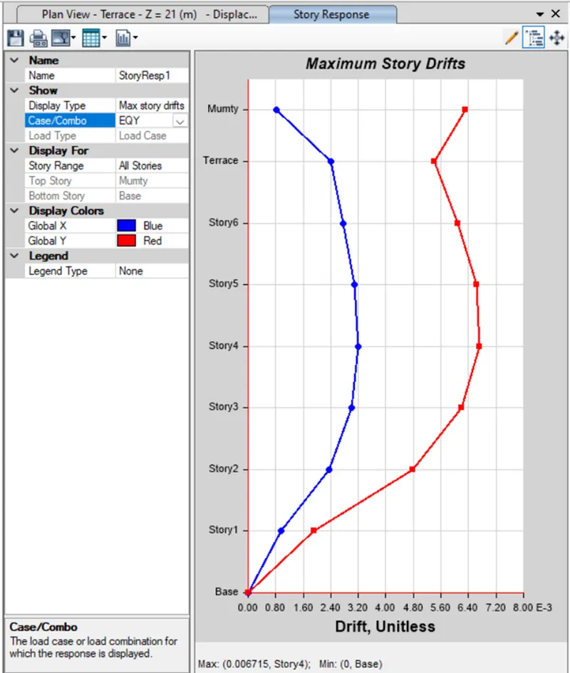
- Inter story drift ratio limited to 0.004 (Achieved)
Result:
To model and analyse the apartment with all seismic consideration, based on given architectural input and to check the seismic performance of an apartment using ETABS and attach the model