Structural Modelling using Etabs 2018
AIM: - To model and analyse the G+7 residential building in zone 5. We have to Run a modal response spectrum analysis and check analysis results of the ETABS model for inter-storey drift requirements, vertical & planar irregularities, minimum shear wall requirements, maximum axial load ratio for column and shear walls, effective moment of inertia for beams and columns etc.
PROCEDURE: -
- Open the ETABS software and first specify the appropriate codes required for this design
- So, in order to do that, first we need to go to the Click on the option Custom Grid spacing and after that just go to the option Edit Grid.
- After doing this a new dialogue box opens named as Grid system data. In that dialogue box based on the sectional elevation, set up the story data and specify the height of each floor as well as the master story height. Specify the all-relevant data in the grid and story section. And just click OK, just as shown in the below given image:
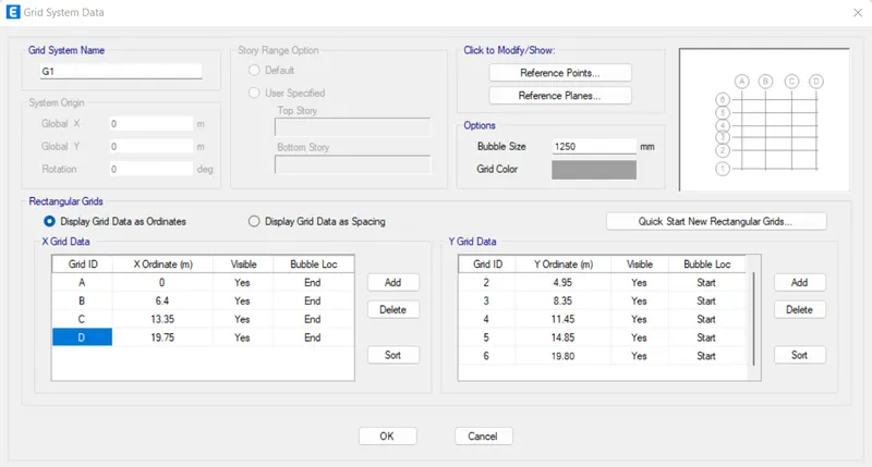
- The above given data is according to the architectural file that have been provided to us with the challenge.
- Now that the grids have been arranged according to the given data, now we have to set the story data also.
- So, in order to do so just click on the Custom Story Data and then click on the option Edit Story Data.
- After clicking the Edit Story Data option there will be another dialogue box named as the Edit Story Data, and we need to add the stories up to the 7 floors so just add the stories.
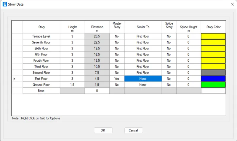
- The story and the grids setup have been completed.
- The plan view and the 3D view are shown below in the image:
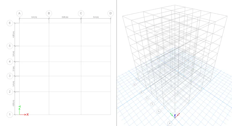
- After setting the grids and the story data now we need to define the materials and the Section Properties as well.
- So, in order to set the material first we need to go to the Define option and there will be a drop-down list in that list there is another option called Material properties.
- After clicking on the Material property there will be another dialogue box named as Define material
- in that dialogue box just click on the option Add New Material.
- Now that all the materials have been added shown in the below given image:
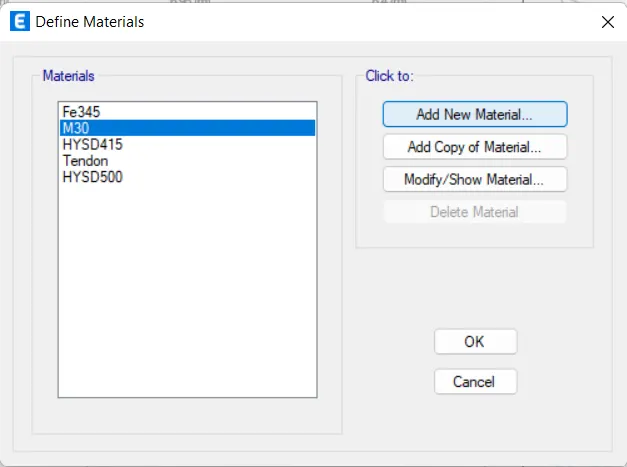
- Now we will have to define the frame properties. We will be adding the columns, slabs shear walls etc.
- So, in order to do that first we need to go to the option Define tab there will be a drop-down list in that list there is another option called Section Properties and then click on the option Frame section, just click on that option.
- After clicking on the Frame section option there will be a dialogue box named as Frame Properties click on the option Add New Property.
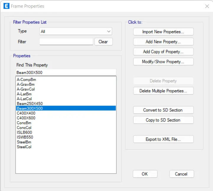
- After adding the columns and the beams in the given plan now we will be adding the slab of thickness 125mm.
- In order to do so first we need to go to the Define tab there will be a drop-down list in that list there will be an option called Section properties and another option called Slab section just click on the option.
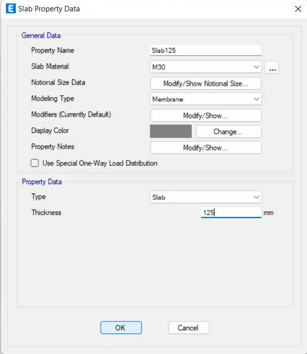
- After that a new dialogue box appears on the screen named as Slab property in this dialogue box there is an option called Add New Property just click on that option.
- After this another dialogue box opens named as Slab Property Data.
SLAB 125 mm:
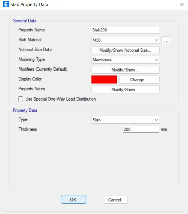
- Similarly, we will be adding the slab for the staircase of 200mm thickness.
- Do the same procedure as we had done for the slab 125 mm.
SLAB (For Staircase) 200 mm:
- Now after adding slab, we will be adding Shear wall. And in order to add shear wall first we need to go to the option Define there will be a drop-down list in that list there will be an option Section Properties and then there will be another option called Wall Section just click on that.
- After this there will be another dialogue box named as Wall Properties, in that dialogue box just click on the option Add New Property.
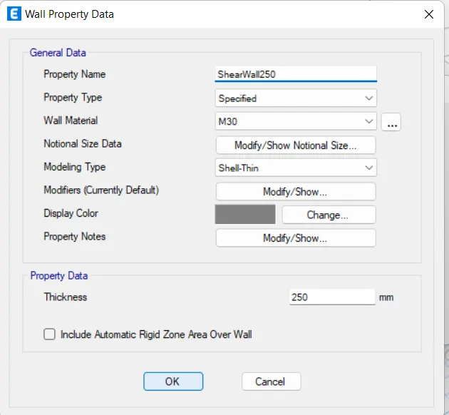
- After clicking on the option Add New Property there will be another dialogue box named as Wall Property Data just as shown in the below given image:
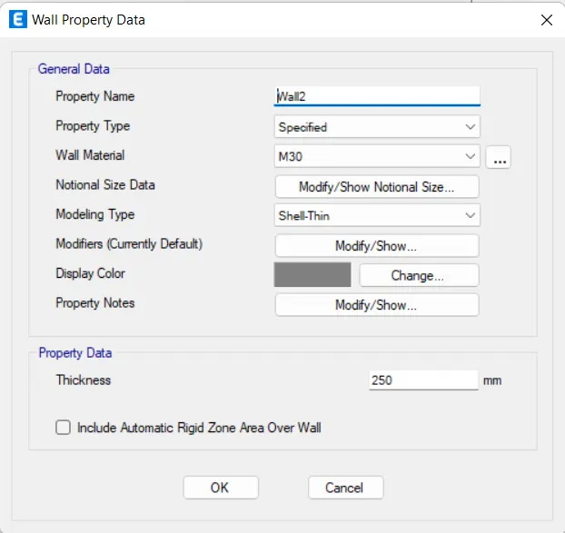
SHEAR WALL 250 mm:
- All the materials and the frame properties have been added.
- Now we have to add the Columns, beams, slab and the shear walls using ETABS software tools.
- Now first let’s add columns using the quick draw column tool available in the software to make easy the positioning of the columns.
- So, in order to use this tool to place the columns in a quick way so first go to the left side of the screen there is an option of quick draw columns just click on that icon.
- Now place the column according to the given AutoCAD file and the requirement of the question. But before placing the column make sure the settings are set to All stories. And now place the column accordingly.
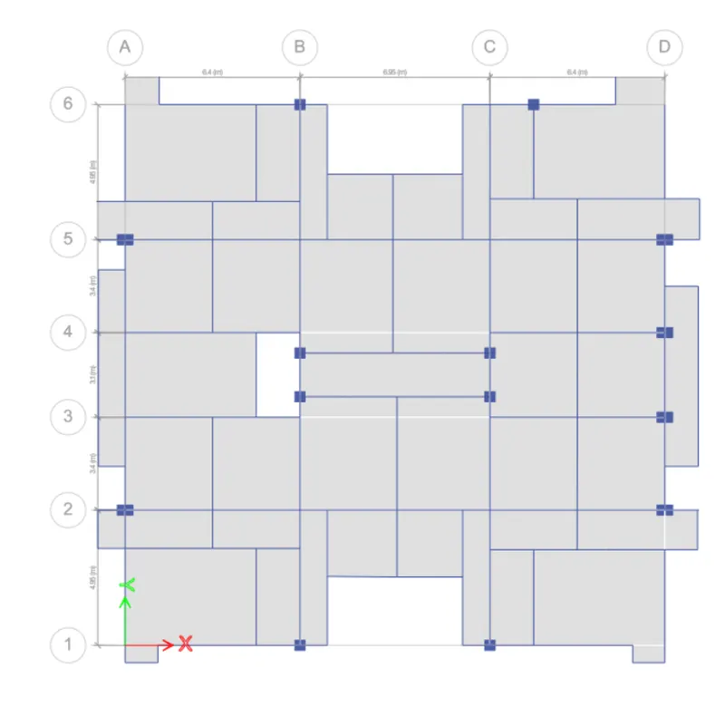
- After adding the secondary beams in the we will be adding the balcony wherever required but before adding the balcony we have to add the slab just by using the option Quick draw floor plan/wall that are present in the left side of the screen just as shown in the below image:
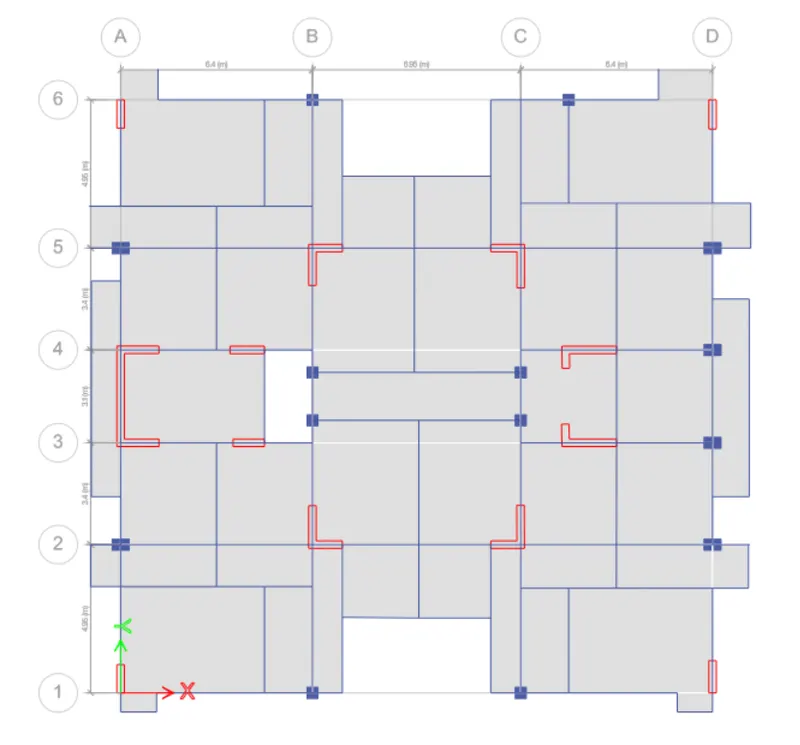
- After adding the slabs and the balcony now add shear walls in their appropriate locations just by using ETABS quick tools to draw the walls and this tool is present at the left-side of the screen just click on that option and draw the shear walls wherever needed just as shown in the below given image:
2D Plan View:
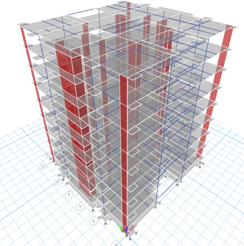
3D View:
- Now we have to fix the connection at the base plan.
- So, in order to do that first we need to go to the base plan and then select all the joints.
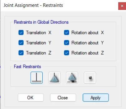
- After that just go to the Assign toolbar then there will be a drop-down list in that list there will be another option called Joint click on that option after clicking on that option there will another drop-down list in that list there will be another option called restraints just click on that option.
- After this there will be another dialogue box named as the Joint Assignment-Restraints, in that dialogue box choose the connection as the fixed connection and then press Apply and then OK just as shown in the below given image:
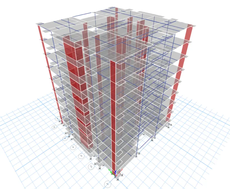
- 3D view of the model after assigning all the properties:
- After assigning all the properties like column, beam, slabs etc now we have to assign the load patterns.
- In order to assign the loads patterns first we need to go to the Define tab then there will be a drop-down list in that list there will be an option called Load Patterns
- After clicking on that option there will be a dialogue box opened named as Define Load Patterns in that dialogue box assign all the loads i.e., Live load, Dead load, super dead loads and the seismic loads just as shown in the below given image:
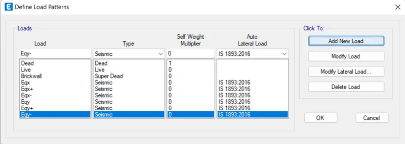
- All the loads have been added after adding the loads now go to the option Modify Lateral Loads and modify the seismic load so here the direction and the eccentricity were selected as the X-direction.
- And now we will be assigning the Brick Wall Load to the given structure.
- So, in order to do that first we need to go to the option Assign then there will be a drop-down list in that list there is an option called Frame Loads click on that after clicking on that there will be another drop-down list in that list there is an option called Distributed.
- After this there will be a dialogue box that appears on the screen named as the Frame Load Assignment- Distributed, in that dialogue box give the Brick wall load as 3.5 KN/sq. and then click Apply and then OK just as shown in the below image:
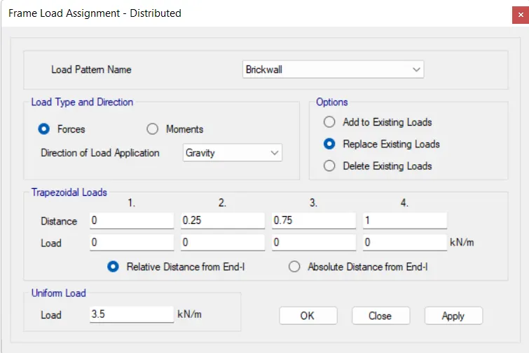
BRICK WALL LOAD-3.5KN/M:
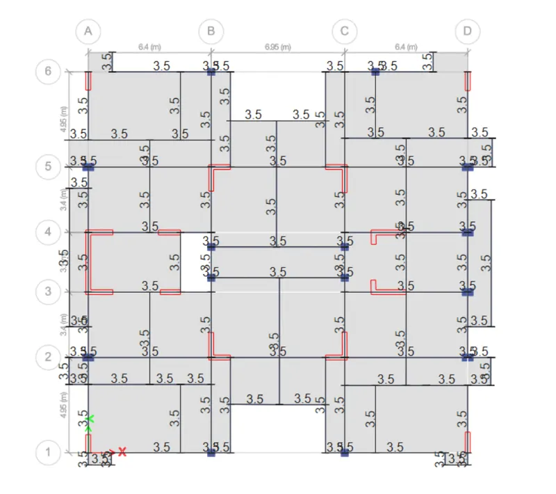
- After applying the dead loads to the structure now we will be applying the live load.
- So, in order to apply the dead load first we need to go to the option Assign and then there will be a drop-down list in that list there is an option called shell load click on that option after that there will be another list in that list click on the option Uniform.
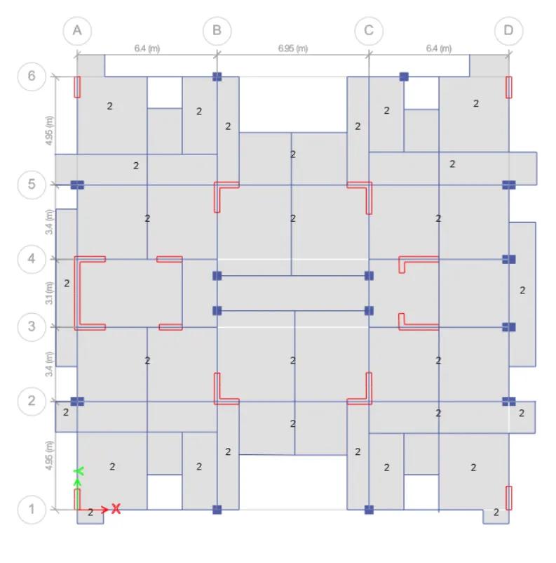
- After clicking the option Uniform there will be another dialogue box named as Shell Load Assignment-Uniform, in that dialogue box fill the relevant data.
For Rooms: 2KN/sq.m
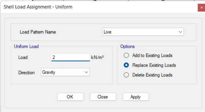
For Bathrooms, staircase, lift: 3KN/sq.m
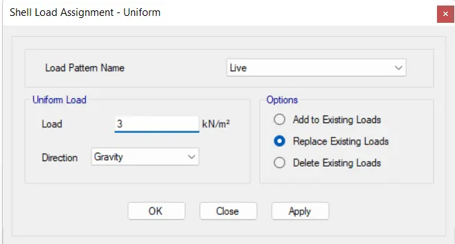
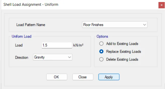
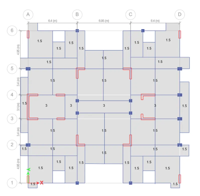
- Now that we have added the live load and the dead load to the structure, now we will be adding the floor finishes to the structure.
- For adding the floor finishes to the structure first select the slabs and then click the option Uniform there will be another dialogue box named as Shell Load Assignment-Uniform, in that dialogue box fill the relevant data.
- Now after assigning the floor finish load now, we will be doing the Live load reduction Factor according to the code.
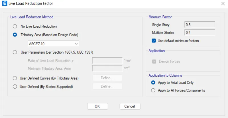
- In order to that first we need to go to the option Design and then go to the option Live Load Reduction Factor.
- After that there will be another dialogue box named as the Live Load Reduction Factor in that dialogue box there will be an option called User Defined just click on that option just as shown in the below given image:
- After that there will be another dialogue box named as the Live Load Reduction by Stories Supported and, in that dialogue, box fill the relevant data just as shown in the below given image:
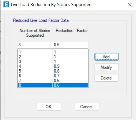
- According to the IS code it states that the buildings that are above the 10 stories, then we have to reduce the Live Load by 50%.
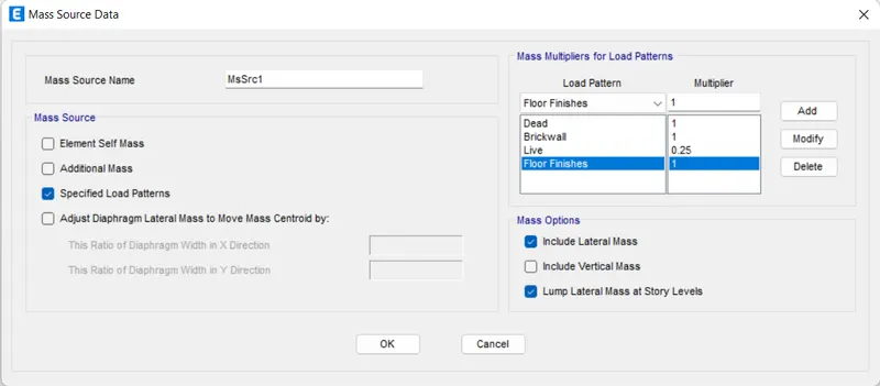
- And now we have to assign the Mass source for this structure.
- In order to do that first we need to go to the option Define then there will be a drop-down list in that list there is an option called Mass source just click on that option.
- After this there will be another dialogue box named as Mass source, in that dialogue box there will be an option called Modify mass source data just click on that option.
- After this there will be another dialogue box named as Mass Source Data, in that dialogue box fill the appropriate data just as shown in the below given image:
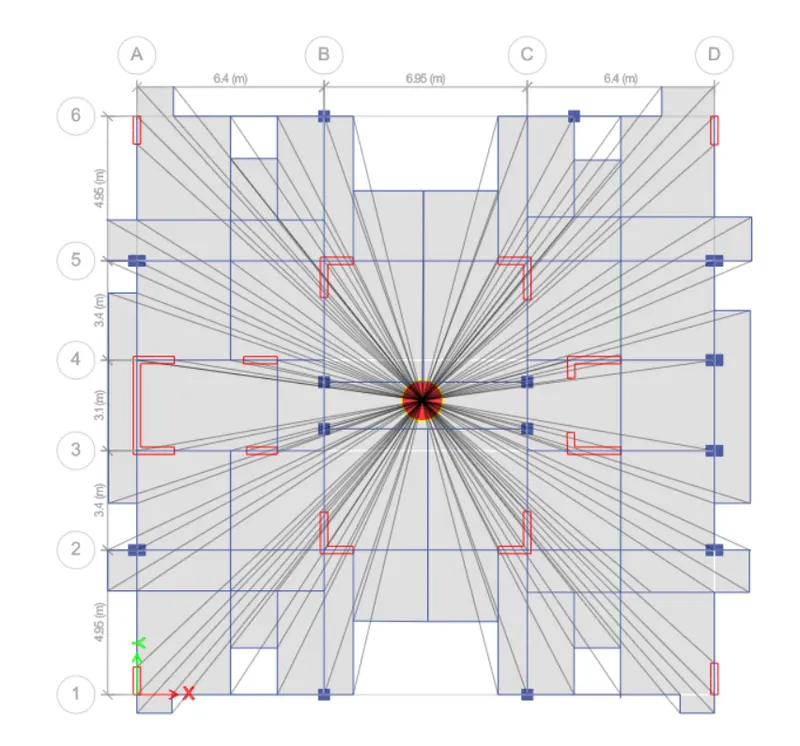
- After assigning the mass source now we have to assign the diaphragm.
- In order to assign the diaphragm, we need to go to the Assign menu and after that there will be a drop-down list and in that list, there is an option called Shell and then there will be another list in that list there is an option called Diaphragm just click on that option.
- There will be a dialogue box named as Shell Assignment Diaphragm in that dialogue box select D1 and then click on the option Apply and then click on OK just as shown in the below given image:
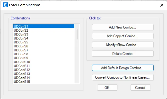
- After assigning the diaphragm now we have to assign the load combinations and in order to do so we need to go to the Define menu then there will a drop-down list and there will be an option called Load combinations just click on that option.
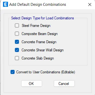
- Then there will be another dialogue box named as the Load combinations and in that dialogue, box click on the option Add Default Design Combos.
- After this there will be another dialogue box named as Add Default Design Combinations in that dialogue box just click on the option Concrete Frame Design and Concrete Shear Wall Design and then click on the option OK just as shown in the below given image:
- Now there will be another dialogue box named as Combinations in that dialogue box all the ETABS generation load combinations are there in that box just as shown in the below given image:
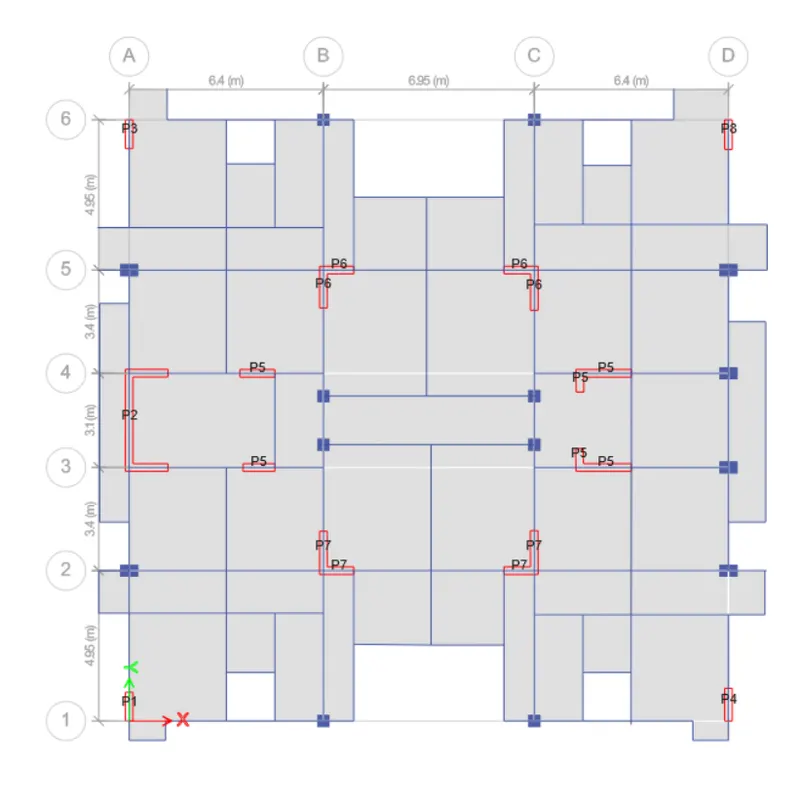
- Now select the pier labels and in order to do so first we need to go to the Assign menu then there will be a drop-down list in that list there will be an option called Shell click on that after that there will be another option called Pier label click on that option.
- After this there will be another dialogue box named as the Pier label in that dialogue box just add the labels or we can say that add the names for the shear walls just like P1, P2, P3 etc.
- Assign the Pier Labels accordingly just as shown in the below given image:
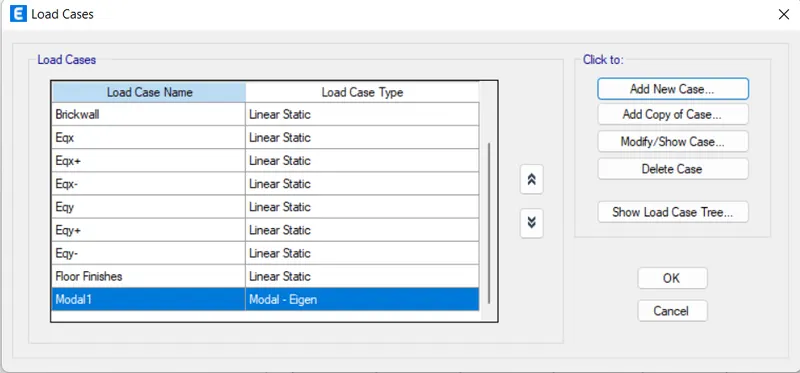
- Now we will be creating the modal analysis and in order to do that go to the Define menu there will be a drop-down list in that list there will be an option called Load Cases just click on that option.
- Now there will be another dialogue box named as the Load Cases in that dialog box there will be another option called Add New Cases just click on that option just as shown in the below given image:
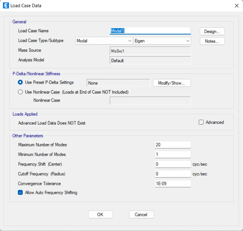
- After clicking the add new case option there will be another dialouge box named as Load Cases in that box enter the data just as shown in the below given image:
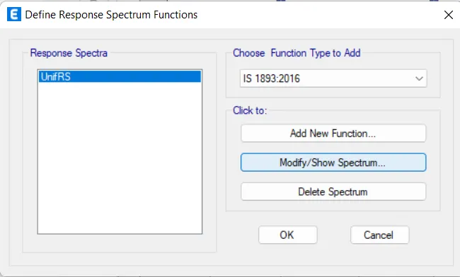
- In order assigning the spectrum analysis just go to the Define menu then there will be a drop-down list and from that list just click on the option Functions and there will be another list and from that list just click on the option Response Spectrum.
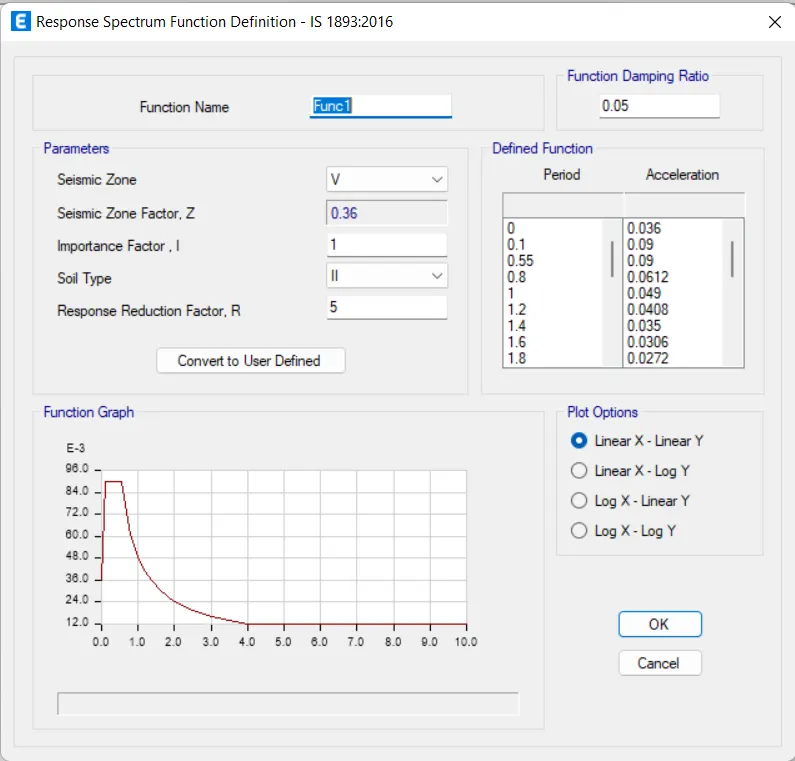
- Then there will be another dialogue box named as Define Response Spectrum Functions in that dialogue box Choose IS 1893:2016 from the option Choose Function Type and then click on the option Add New Function just as shown in the below given image:
- After clicking the option then there will be another dialogue box named as Response Spectrum Function Definition-IS 1893:2016, in that dialogue box fill the data just as shown in the below given image:
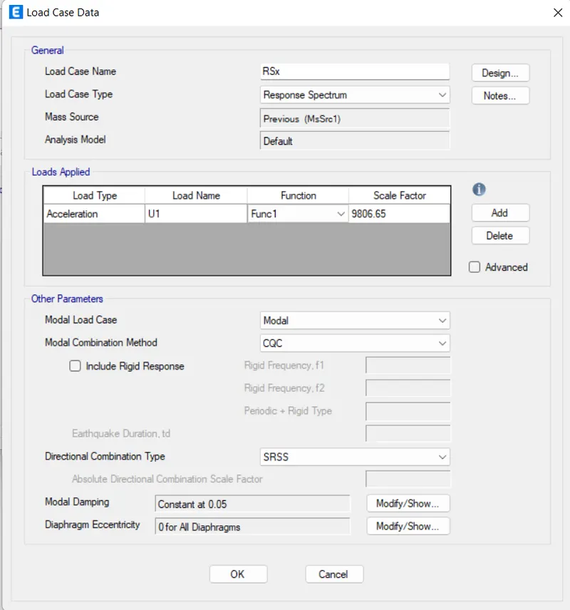
The Response Spectrum Load Case in X-Direction: RSx
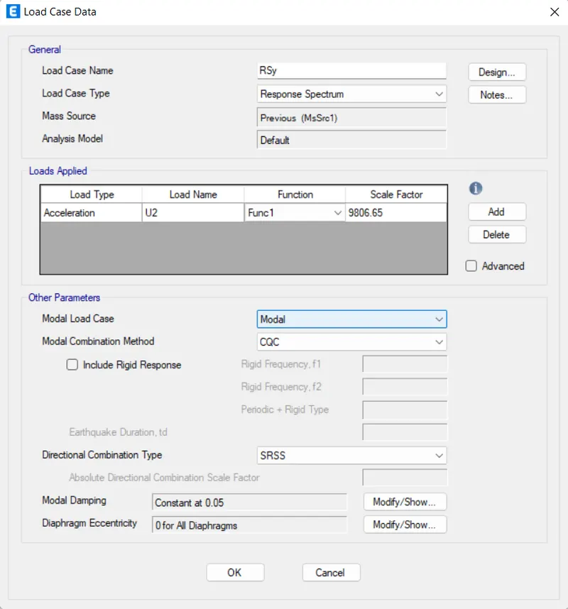
The Response Spectrum Load Case in Y-Direction: RSy
- Now after this we will check the model and do the Run Analysis.
- So, in order to check the model, we need to go to the Analyse menu click on that then there will be a drop-down list in that list click on the option Check model.
- Now click on the Check Model option and let the ETABS check the model for us just as shown in the below given image:
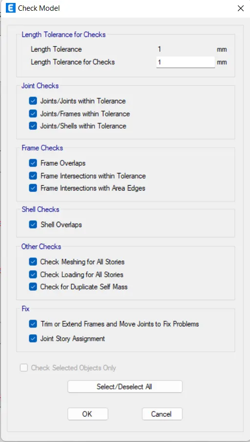
- Now that the model has been checked and there are no warnings messages.
- After checking the model with no warning do the Run analysis.
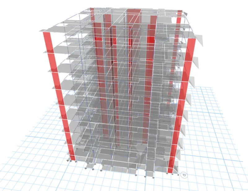
- Now we will be reviewing the analysis results to see if the model is structurally stable or not or if this model needs a revision.
- So, in order to do that first we have to check the Base Shear.
Base Shear Check:
- To check the base shear just go to the Display menu then there will be a drop-down list in that list there is an option called Show table just click on that option.
- After that there will be a dialogue box named as the Choose Tables for Display and in that dialogue box there will be an option called ANALYSIS RESULT click on that after that click on the Structure Output and then click on Base Reaction and then click OK just as shown in the below given image:
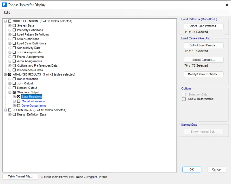
- After that there will be another dialogue box named as Base reactions and in that dialogue box it contains all the information regarding the Base reactions.
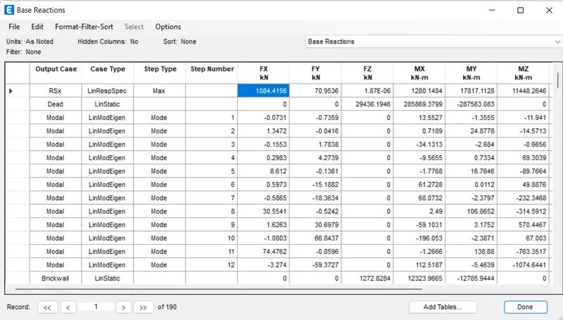
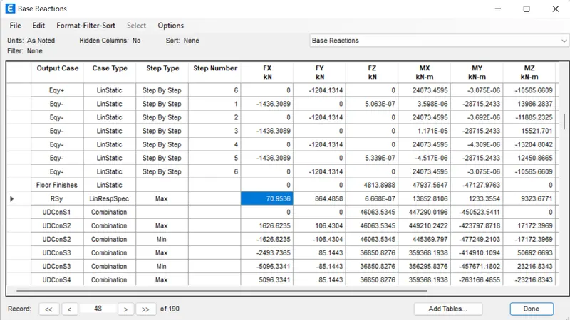
- And according to the codebook it is said that the response spectrum base shear must be at least equal to the same that is obtained by the linear analysis.
- So below is the given image from the both results in X and Y direction both:
Base shear scaling:
- As we can see from the above image that the response spectrum base shear is less as compared to EQx and EQy.
- So now what we have to do is increase the scale of the response scale spectrum load cases in X and Y so that it matches the base shear value.
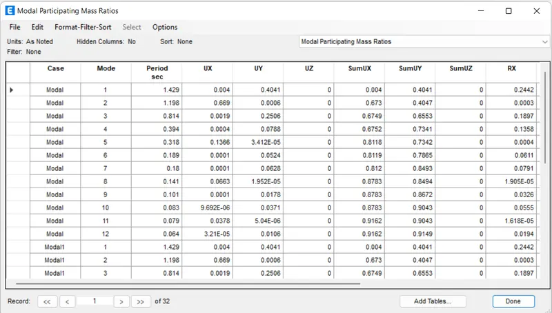
Modal Participation Ratio:
- In order to check the modal participation ratio just go to the Display menu then there will be a drop-down list in that list there is an option called Show table just click on that option.
- After that there will be a dialogue box named as the Choose Tables for Display and in that dialogue box there will be an option called ANALYSIS RESULT click on that after that click on the Structure Output and then click on Modal Information and then click OK.
Modal Participation ratio result is given below:
Story Response Spectrum:
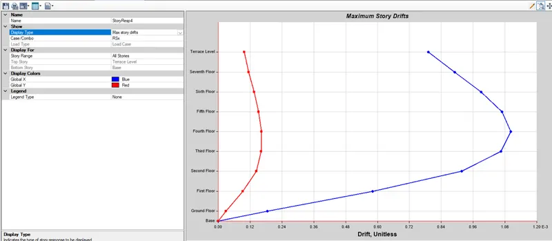
- In order to find the story response spectrum first we need to go to the display tab there will be an option called Story Response plot just click on that option.
- Now there will be another dialogue box change the Display type as Maximum story drifts and Case/Combo as RSx just as shown in the below given image:
- And do the same procedure to get the story drift in Y-direction i.e. RSy just as shown in the below given image:
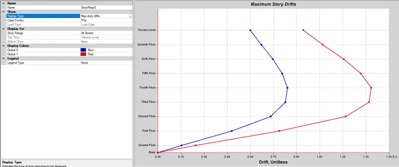
- So according to the IS: 1893, it suggests that the allowable maximum inters story drift is of 0.4%.
- Now open the reaction tab from the top of the screen there is a tab click on that tab or just press F7 the new dialogue box name as Reactions opens after that in the dialogue box select the earthquake load Towards the X-direction and then just click Apply and then OK just as shown in the below given image:
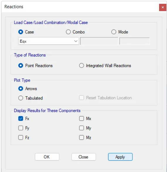
- From the IS code we know that the shear wall should take at least 80% of the load.
- The base shear reactions are shown in the below given image:
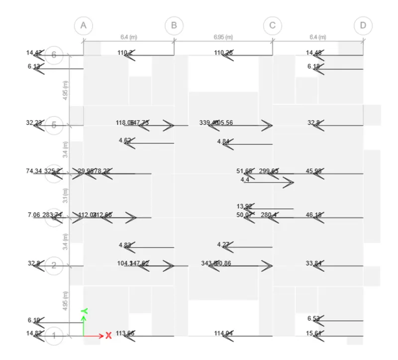
- So, in order to find the percentage value for the load capacity of the shear wall divide the base shear which is taken by shear wall with the base shear of the building and if the number of the percentage is 80% then there is no need to provide more shear walls.
- But if the percentage is less than 80% then we have to provide more shear wall in our structure.
- Now here in our structure the number of shear walls is sufficient.
- Finally, the model has been analysed successfully.