Drafting of various geometries using Chamfer, Fillet tool in AutoCad
COMMAND USED IN THIS CHALLENGE ARE
- LINE
- CIRCLE
- RECTANGLE
- COPY
- MIRROR
- OFFSET
- TRIM
- POLYGON
- POINT
- ROTATE
- FILLET
- CHAMFER
AIM :- To draw the figure 01 using AutoCAD
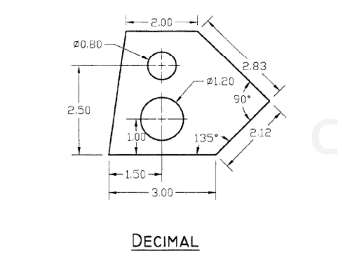
PROCEDURE :- Type “L” or select line from draw toolbar
- Specify first point: 1,1 then enter
- Specify next point: @3<0 then enter
- Specify next point: < Polar on at angle of 45 >2 then enter
- Specify next point: moving curser to left 2.83 then enter
- Specify next point: @2<180 then enter
- Specify next point: C then enter
Type “C” or select from draw toolbar
- Specify centre point: select mid point of the base line 1 then enter
- Specify radius of circle: D then enter
- Specify diameter of circle: 1.20 then enter
Type “C” or select from draw toolbar
- Specify centre point: select mid point of the base line 2.50 then enter
- Specify radius of circle: D then enter
- Specify diameter of circle: 0.80 then enter
After that use “DIMLINEAR” for the dimensions and “DIMANGULAR” for the angles all of the drawn figure
RESULT :-
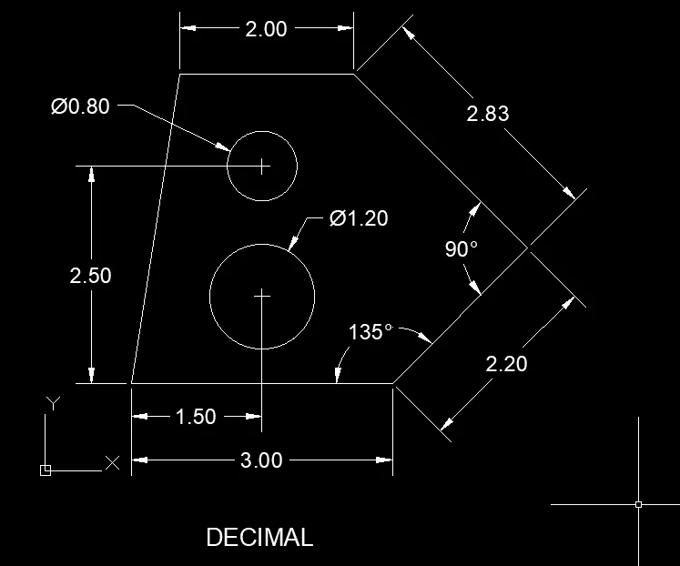
- The resultant figure is as follows with dimensions
- All dimensions are in meter
AIM :- To draw the figure 02 using AutoCAD
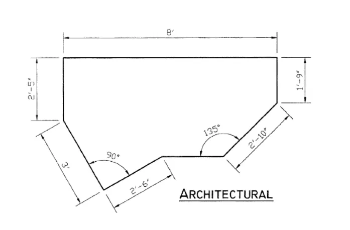
PROCEDURE :- 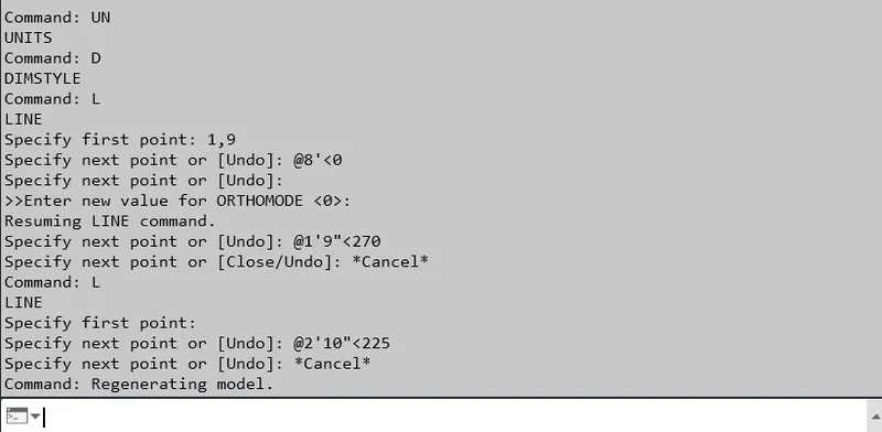
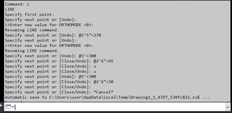
After that use “DIMLINEAR” for the dimensions and “DIMANGULAR” for the angles all of the drawn figure
RESULT :-
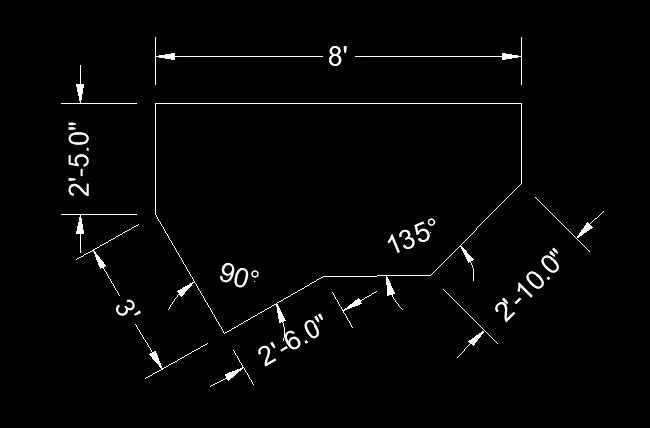
- The resultant figure is as follows with dimensions
- All dimensions are in feet & inches.
AIM :- To draw the figure 03 using AutoCAD
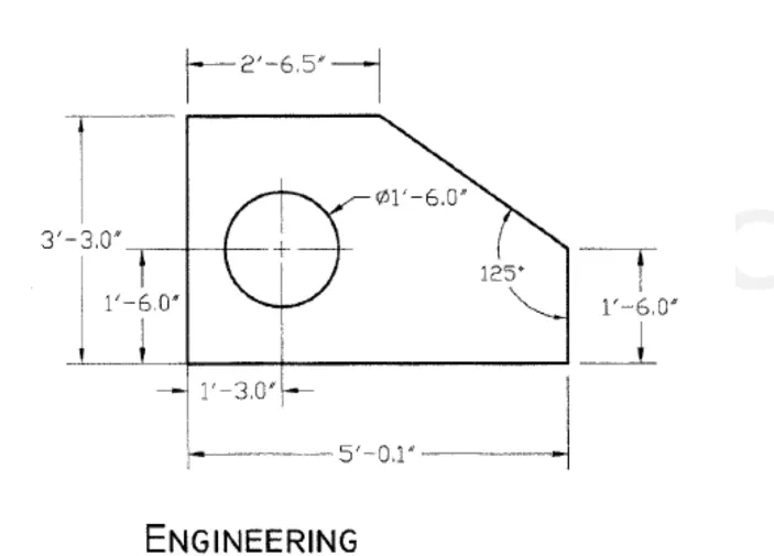
PROCEDURE :- 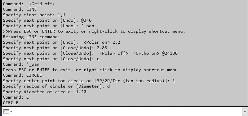
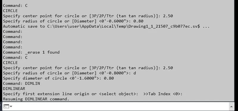
After that use “DIMLINEAR” for the dimensions and “DIMANGULAR” for the angles all of the drawn figure
RESULT :- 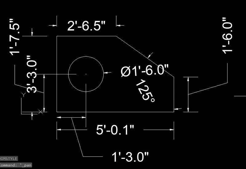
- The resultant figure is as follows with dimensions
- All dimensions are in feet & inches.
AIM :- To draw the figure 04 using AutoCAD
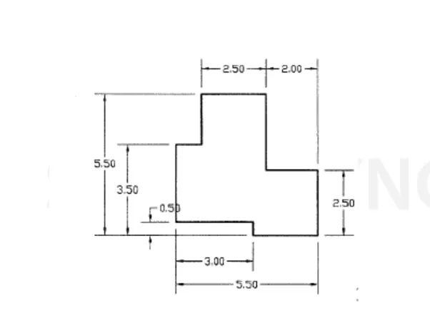
PROCEDURE :- 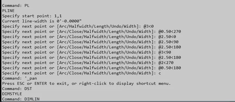
After that use “DIMLINEAR” for the dimensions and “DIMANGULAR” for the angles all of the drawn figure
RESULT :- 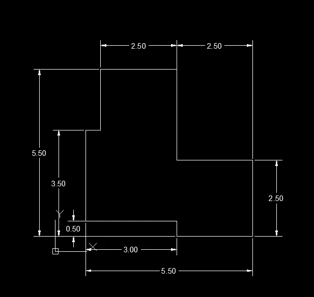
- The resultant figure is as follows with dimensions
- All dimensions are in meter
AIM :- To draw the figure 05 using AutoCAD
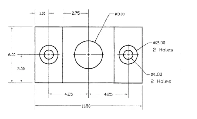
PROCEDURE :- 
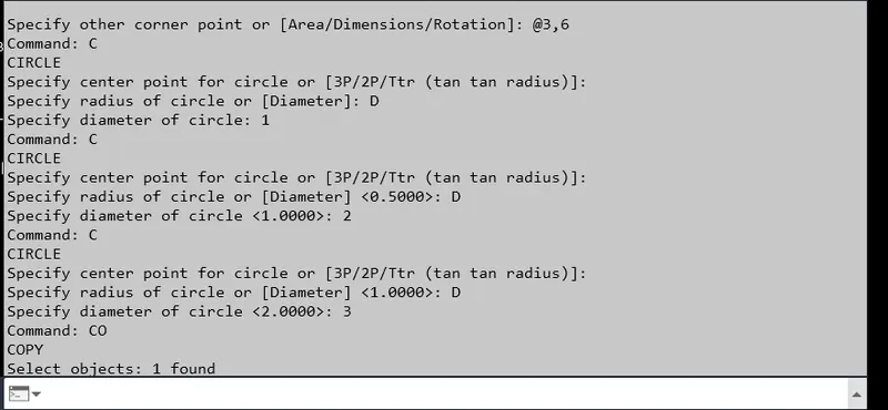
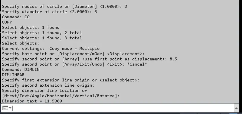
After that use “DIMLINEAR” for the dimensions and “DIMANGULAR” for the angles all of the drawn figure
RESULT :-
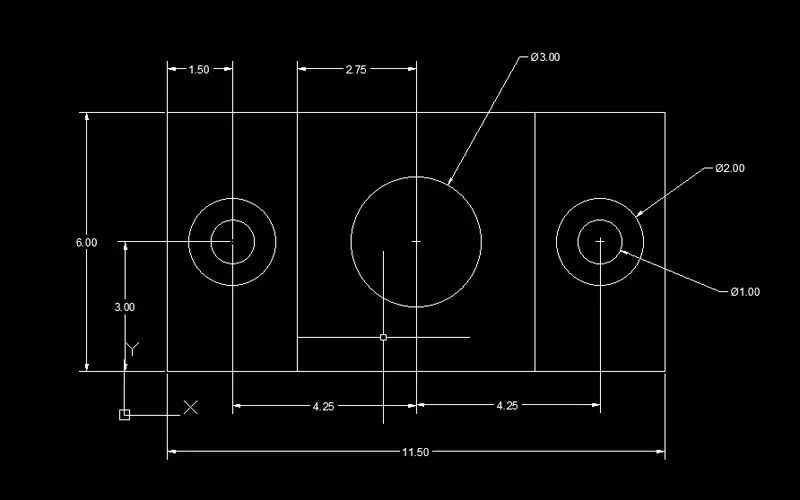
- The resultant figure is as follows with dimensions
- All dimensions are in meter
AIM :- To draw the figure 06 using AutoCAD
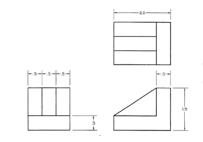
PROCEDURE :- 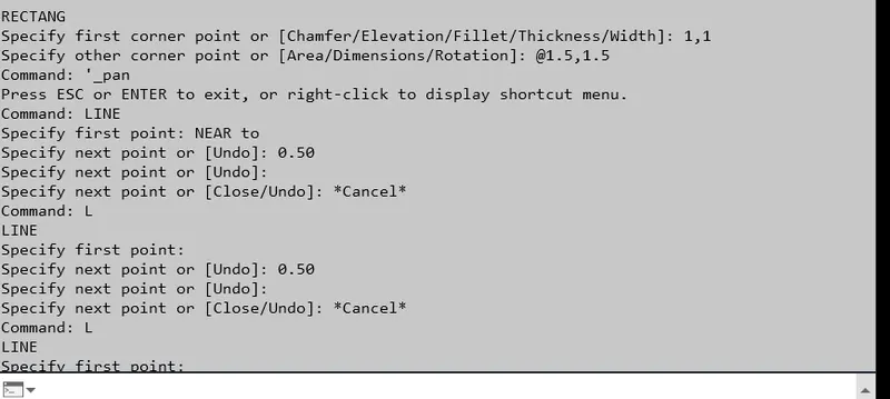
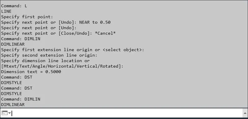
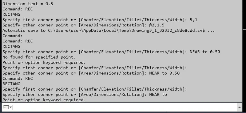
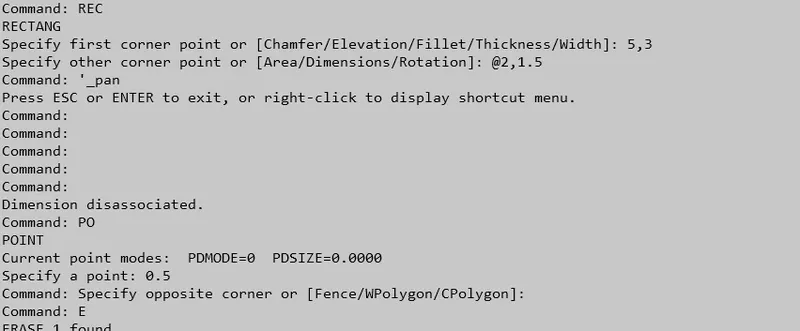
After that use “DIMLINEAR” for the dimensions and “DIMANGULAR” for the angles all of the drawn figure
RESULT :-
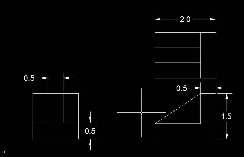
- The resultant figure is as follows with dimensions
- All dimensions are in meter
AIM :- To draw the figure 07 using AutoCAD
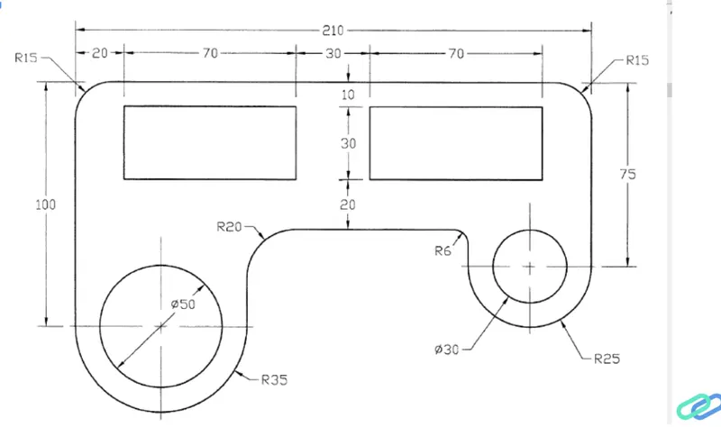
PROCEDURE :- type "REC" or select rectangle from draw toolbar
- specify first corner:1,10 then enter
- specify other corner: @210,100 then enter
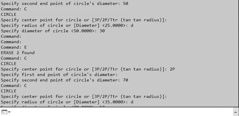
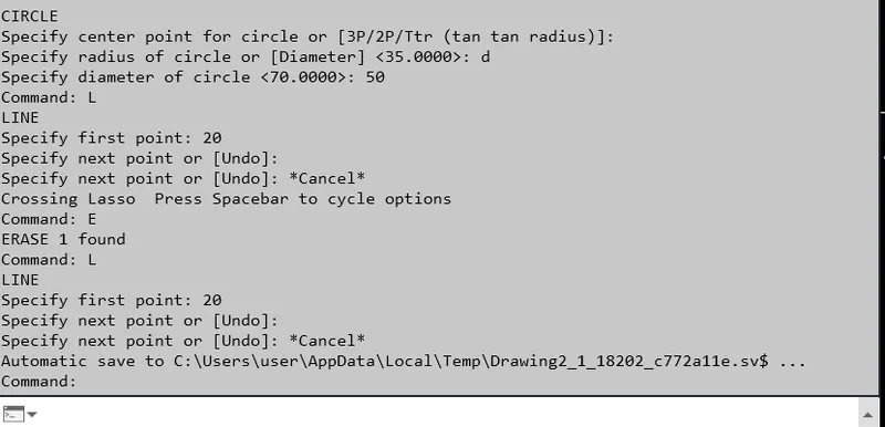
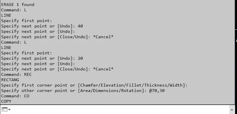
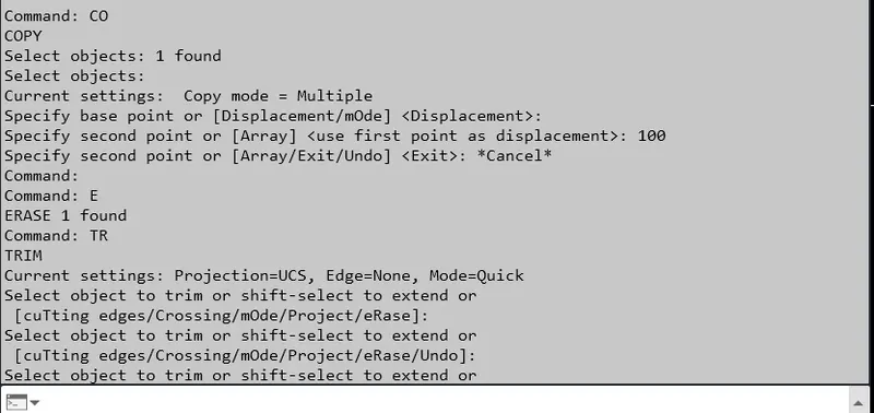
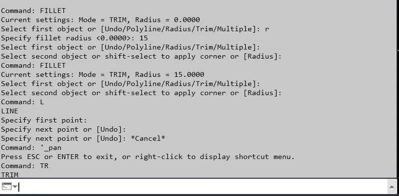
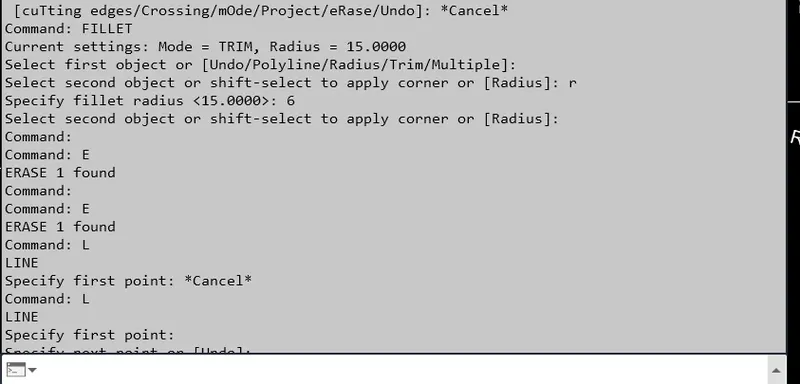
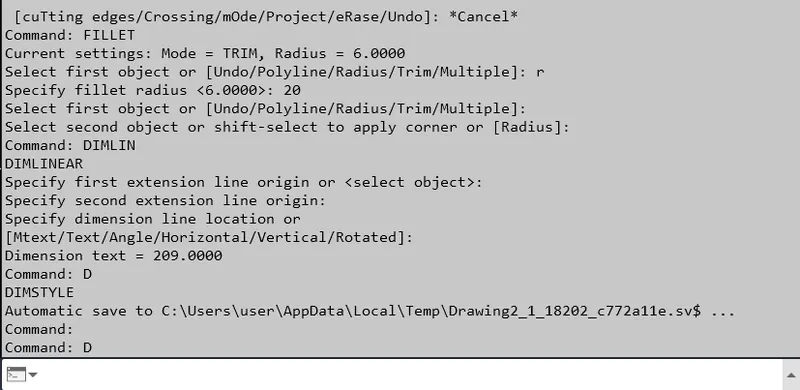
After that use “DIMLINEAR” for the dimensions and “DIMANGULAR” for the angles all of the drawn figure
RESULT :-
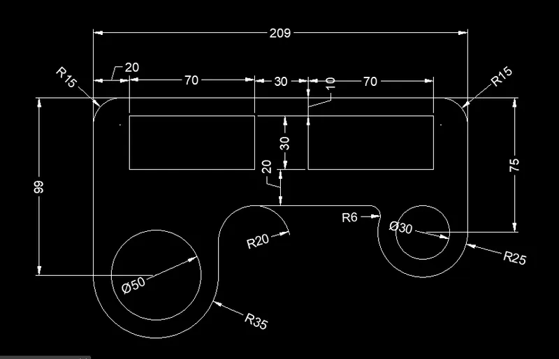
- The resultant figure is as follows with dimensions
- All dimensions are in meter
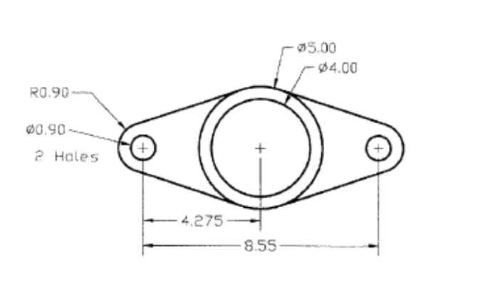
AIM :- To draw the figure 08 using AutoCAD
PROCEDURE :-
:- Type “C” or select circle from toolbar
- Specify center point: 1,10 then enter
- Specify radius of circle: D then enter 0.90 then enter
Type “C” or select circle from toolbar
- Specify center point: select center of circle
- Specify radius of circle: 0.90 then enter
Type “L” or select from toolbar
- Specify first point: select center of the circle
- Specify next point: @8.55<0 then enter
Type “C” or select circle from toolbar
- Specify center point: select mid of line
- Specify radius of circle: D then enter 4.0 then enter
Type “C” or select circle from toolbar
- Specify center point: select mid of line
- Specify radius of circle: D then enter 5.0 then enter
Type “CO” or select copy from toolbar
- Select object: select the both circle of left
- Specify base point: select the center of circle
- Specify second point: put at the right side of line
Type “L” or select line from toolbar for both circle left & right
- Specify first point: type tan and press enter
- Specify next point: type tan enter
after that trim all the unwanted lines.
After that use “DIMLINEAR” for the dimensions and “DIMANGULAR” for the angles all of the drawn figure
RESULT :-
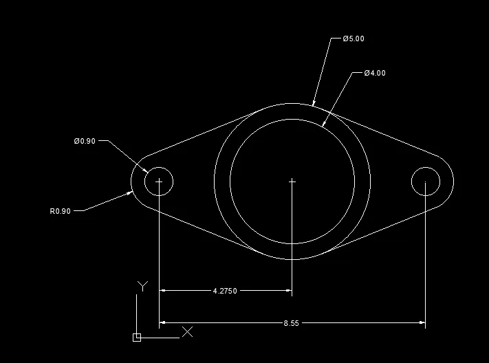
- The resultant figure is as follows with dimensions
- All dimensions are in meter
AIM :- To draw the figure 09 using AutoCAD
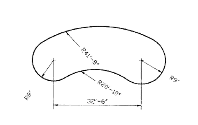
PROCEDURE :- Type “C” or circle command or select from draw toolbar
- Specify center point for circle: 10,10 then enter
- Specify radius of circle: 8’ then enter
Type “L” or line or select line from toolbar
- Specify first point: select center of circle
- Specify next point: @32’6”<0 then enter
Type “C” or circle command or select from draw toolbar
- Specify center point for circle: select end of line
- Specify radius of circle: 9’ then enter
Type “C” or circle command or select from draw toolbar
- Specify center point for circle: select Ttr
- Specify point on object for first tangent of circle: select at the top of first circle
- Specify point on object for second tangent of circle: select at the top of second circle
- Specify radius of the circle: 41’8” then enter
Type “C” or circle command or select from draw toolbar
- Specify center point for circle: select Ttr
- Specify point on object for first tangent of circle: select at the bottom of first circle
- Specify point on object for second tangent of circle: select at the bottom of second circle
- Specify radius of the circle: 20’10” then enter
Type “TR” or select trim from modify toolbar
Then trim the all unwanted line or circles over there.
After that use “DIMLINEAR” for the dimensions and “DIMANGULAR” for the angles all of the drawn figure
RESULT :-
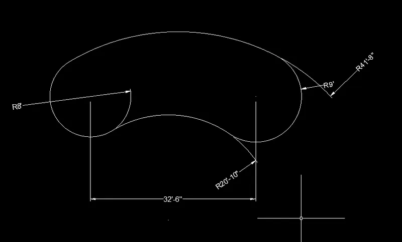
- The resultant figure is as follows with dimensions
- All dimensions are in feet & inches.
AIM :- To draw the figure 10 using AutoCAD
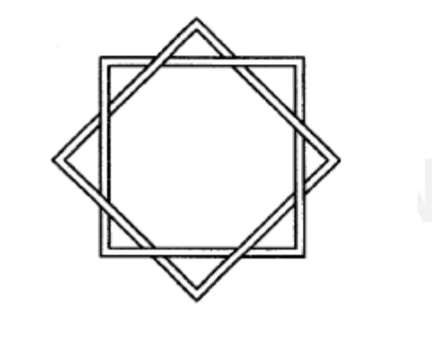
PROCEDURE :- 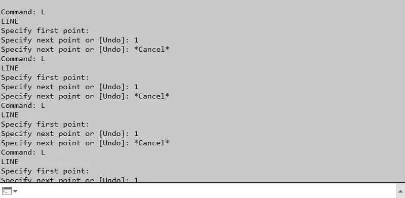
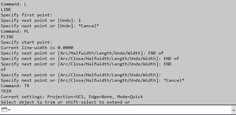
After that use “DIMLINEAR” for the dimensions and “DIMANGULAR” for the angles all of the drawn figure
RESULT :-
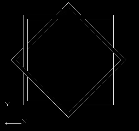
- The resultant figure is as follows with dimensions
- All dimensions are in meter
AIM :- To draw the figure 11 using AutoCAD
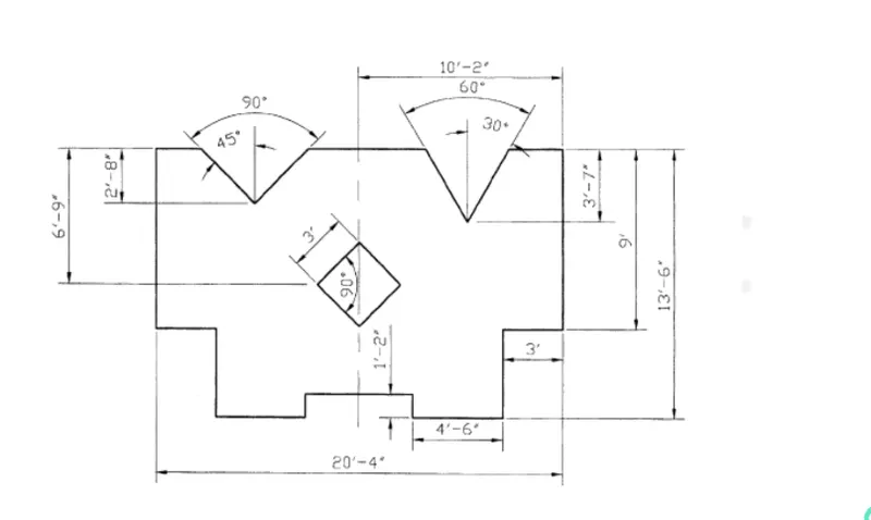
PROCEDURE :- Type “L” or select line from toolbar
- Specify first point: 1,5 then enter
- Specify next point: @9’<90 then enter
- Specify next point: @20’4”<0 then enter
- Specify next point: @9’<270 then enter
- Specify next point: @3’<180 then enter
- Specify next point: @4’6”<270 then enter
- Specify next point: @4’6”<180 then enter
- Specify next point: @1’2”<90 then enter
- Specify next point: @4’6”<180 then enter
- Specify next point: @1’2”<270 then enter
- Specify next point: @4’6”<180 then enter
- Specify next point: @4’6”<90 then enter
- Specify next point: @3’<180 then enter
Type “L” or select line from toolbar
- Specify first point: select mid of top side rectangle
- Specify next point: @6’9”<270 then enter
Type “REC” or select rectangle from toolbar
- Specify first corner: select end if last line
- Specify other corner: @3’<90 then enter
Type “L” or select line from toolbar
- Specify first point: select the left corner of rectangle
- Specify next point: @5’1”<0 then enter
- Specify next point: @2’8”<270 then enter
Polar mode on at 45 degree
Type “L” or select line from toolbar
- Specify first point: select the end of line
- Specify next point: using curser towards the 45 degree then enter
Type “L” or select line from toolbar
- Specify first point: select the end of line
- Specify next point: using curser towards the 135 degree then enter
Type “L” or select line from toolbar
- Specify first point: select the right corner of rectangle
- Specify next point: @5’1”<180 then enter
- Specify next point: @3’7”<270 then enter
Polar mode on at 30 degree
Type “L” or select line from toolbar
- Specify first point: select the end of line
- Specify next point: using curser towards the 30 degree then enter
Type “L” or select line from toolbar
- Specify first point: select the end of line
- Specify next point: using curser towards the 120 degree then enter
Type “TR” or select trim from modify toolbar
Then trim the all unwanted line or circles over there.
After that use “DIMLINEAR” for the dimensions and “DIMANGULAR” for the angles all of the drawn figure
RESULT :-
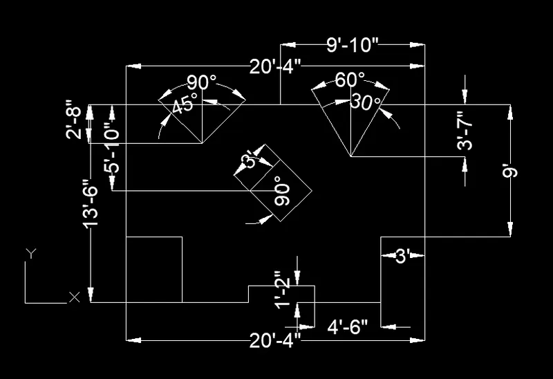
- The resultant figure is as follows with dimensions
- All dimensions are in feet & inches.