Structural dynamics
1. Differentiate Static analysis and Dynamic analysis
when the loads of displacement are applied in very slowly to a structure inertia of forces that equals to mass and acceleration are negligible.
and may be disregarded in a force equilibrium .when load is applied very slowly,this correspondance to what is normally referred to static response of structure.
the force doesnot varies with time. the variation of forces with respect to time is negligable assume with constant in static analysis.
the inertia of forces cannot be disregarded in the equilibrium equation and the structure response dynamically to the exact region.
further more damping forces may also develop and should also be considered to equilibrium of motion equation.
so, the three fundamental differences are mentioned here,
- varition of load with time
- motion cannot be disregarded
- two additional forces of elasticity.must be accounted
inertia forces
damping forces
more degree of freedom are typically necessary to define the stiffness properties of a structure compared to the degree of freedom necessary for dynamic analysis
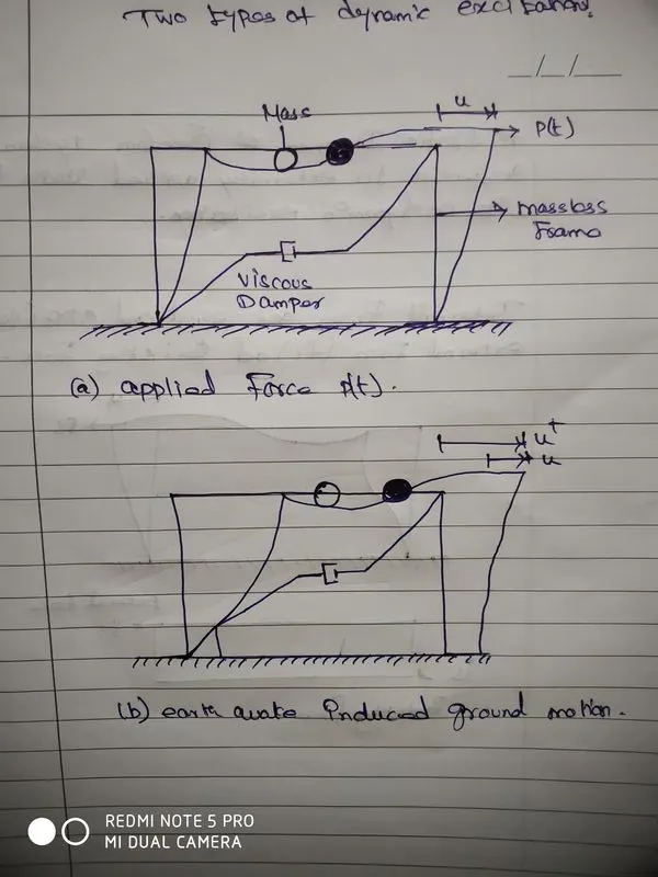
system consisting of mass (m) stifness (k) and viscous damper
an idealization of a one story structure
the number of independent displacement required to define the displaced position of all the masses relative to their original position is called the no.of degree of freedom for dynamic analysis.
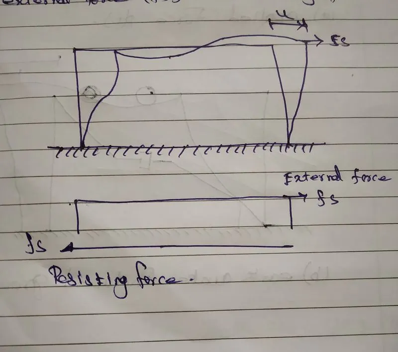
a static degree of freedom system subjected to extremely applied static force with no dynamic excitation.
internal forces are equal and applied to opposite to external fs and resisting forces
2.
Elastic behavior
which basically assume the deformation are smaller.
the assumption of linear elastic is only when the deformation are not that large because the moment that deformated get large that the relationship between external force (fs) and displacement (u) no longer linear it will became non linear .
the value of (k) is constant,
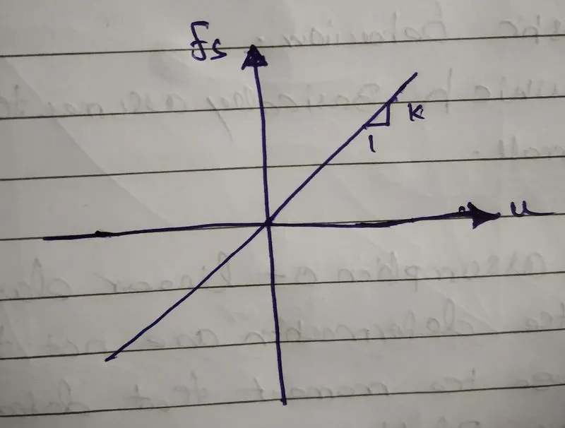
for a linear system relationship between the lateral forces (fs) and resulting deformation (u) is linear that is
fs = k.
where (k) is the lateral stiffness of the system its unit are force/length.
consider the frame below with width (L) height (h) elastic modulus (E) and secomd momemt of the axis of bending = lb and lc for the beam and columns respectively the column are fixed at the base
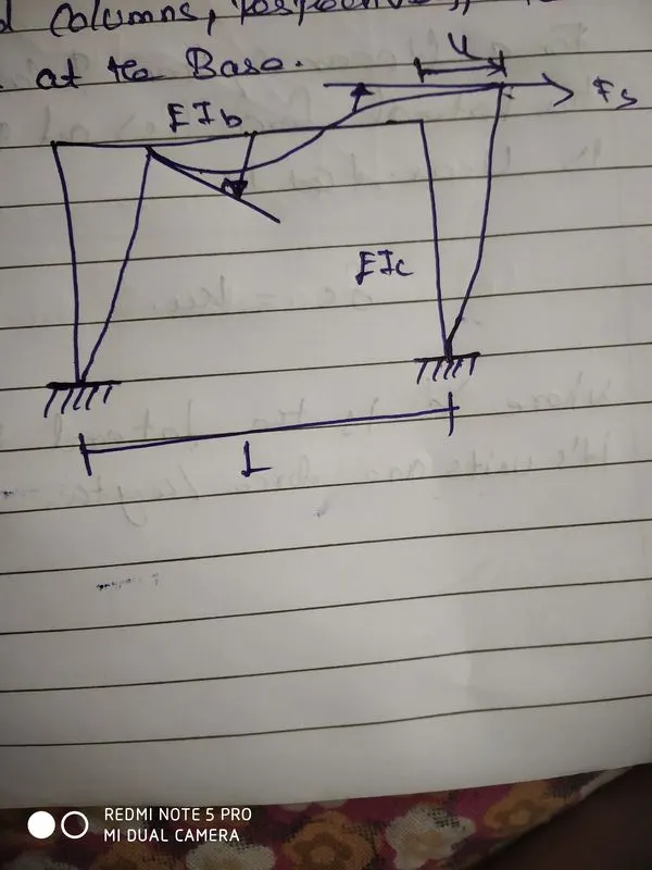
it assumes that columns and beams are inextensible which means actual deformation of the three elements in this frame.
this assumption actually reduce the static analysis problem it helps as reduce the static degree of freedom of three.
2 lateral displacements in vertical and horizontal direction of one joint rotation in one point and same 2 lateral displacements and one joint rotational in other end totally there are 6 degree of freedoms
the lateral stiffness of the frame can readly be determined for the two extreme cases. if the beam is rigid i.e., with flexural rigidity Elb = infinity and for a beam with no stiffness i.e., Elb =0.
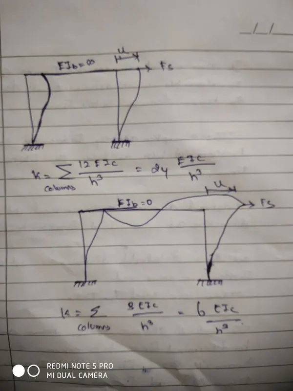
at first image the frame is infinitly rigid .so, how it will reform under the lateral force.
this column behave as a two fixed connects at the top and bottom and net lateral stiffness frame will be 24 EIc/h3.
and another image is the extreme scenario where the beam stifness in that case it has 2 column behave like vertical cantilever base.
the lateral stiffness of the frame lies between these values of (k).
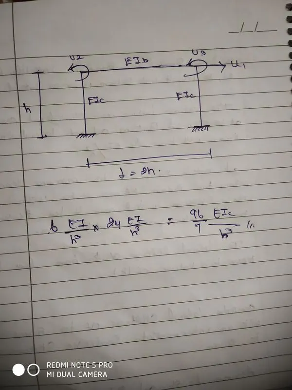
compute the lateral stiffness of the frame with an intermediate realisitic stiffness of the beam.
assume L = 2h and EIb = EIc.
Inelastic behavior
under cyclic deformation due to earth quake the initial loading curve is non linear and amplitude of deformation.
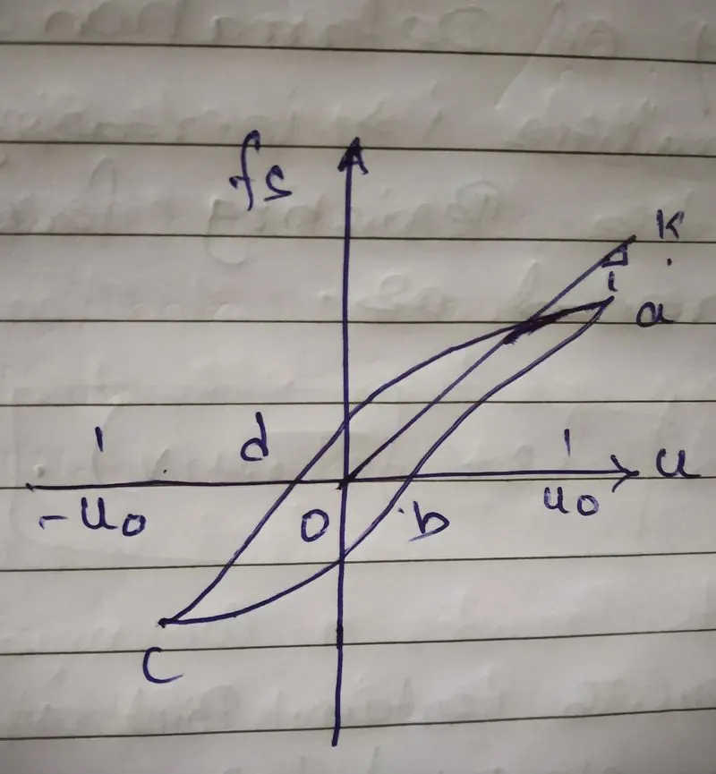
in this graph the o-a is a initial loading curve it is linear from the start and at end it became non linear. so,after the initial loading curve and re loading curves which are differ from initial loading branch.in case of any sort of cyclic loading it became nonlinear at certain point.
force displacement relationship becames non linear and inelastic at large deformation
force fs corresponding to deformation is not single valued and depends on history of deformation and wheather the resisting force can be expressed as
fs = fs(u,v)
after the certain point it becames non linear at point (a). then there is unloading the path and the load moves in the negativr direction does the (U) displacement.
then there is laod again and the again load it does not follow the exact same path.
then this path created aat every loading and unloading chart a new path itselfs.
the lateral deformation is not ina single value and it depends on the history of deformation.
plastic behaviour
the assumption of linear elastic is only when the deformation are not that large because the moment that deformated get large that the relationship between external force (fs) and displacement (u) no longer linear it will became non linear .
the value of (k) is constant,
for a linear system relationship between the lateral forces (fs) and resulting deformation (u) is linear that is
fs = k.
where (k) is the lateral stiffness of the system its unit are force/length.
Non-linear Inelastic behavior
under cyclic deformation due to earth quake the initial loading curve is non linear and amplitude of deformation.
in this graph the o-a is a initial loading curve it is linear from the start and at end it became non linear. so,after the initial loading curve and re loading curves which are differ from initial loading branch.in case of any sort of cyclic loading it became nonlinear at certain point.
force displacement relationship becames non linear and inelastic at large deformation
force fs corresponding to deformation is not single valued and depends on history of deformation and wheather the resisting force can be expressed as
fs = fs(u,v)
after the certain point it becames non linear at point (a). then there is unloading the path and the load moves in the negativr direction does the (U) displacement.
then there is laod again and the again load it does not follow the exact same path.then this path created aat every loading and unloading chart a new path itselfs.the lateral deformation is not ina single value and it depends on the history of deformation.
if we want to know the value of corresponding point b and u0 we have three degree of freedom options.it can be at any deformation of intersection of both laoding and unloading paths.
this is the reason.the force is not at single veluae it is depend on the loading and unloDINg path (history of deformation)
if the load fs goes upto the intersection point o to k it does not path in differrent way back.it comes along with its original position.
3.Mass, Stiffness & Damping components in the equation of motion
The static degree of freedom system can be viewed as a combination of three pure, independant systems:
the stiffness component: the frame without damping or mass. The external force fs on the stiffness component is related to displacement u by fs = ku, if the system is linearly
elastic the damping component: the frame with its damping property but no stiffness or mass. The external force on the damping component is related to velocity by fd = cv
the mass component: the roof mass without the stiffness or damping of the frame. The external force fi on the mass component is related to the acceleration by fi= mü
mü+fD+ fs = p(t) - mü + cu+ku = p(t) *
4. Relationship between Natural period (Tn) & Natural frequency (f)
Natural period of vibration of the system (T) - the time required for the undamped system to complete one cycle of free vibration (unit is seconds). It is related to the natural circular frequency of vibration, w, in units of radians per second:
Tn= 2π/wn, or wn = 2π/Tn,
Natural cyclic frequency of vibration of the system - the number of cycles (or one complete revolution) executed by system in 1 second (unit is hertz).
fn=1/Tn
The natural vibration properties w, T, and f, depend only on the mass and stiffness of the structure
k = mw²
The stiffer of two SDF systems having the same mass will have the shorter natural period (less time to complete one cycle) and the higher natural frequency
Similarly, the heavier (more mass) of two structures having the same stiffness will have the longer natural period and the lower natural frequency.
wn = square root of k/m.
5. Response spectrum
A central concept in earthquake engineering, response spectrum is a practical means of characterizing ground motions and their effects on structures of different T
It provides a convenient means to summarize the peak response of all possiblelinear single degree of freedom systems to a particular component of ground motion.
It also provides a practical approach to apply the knowledge of structural dynamicsto the design of structures and development of lateral force requirements inbuilding codes.
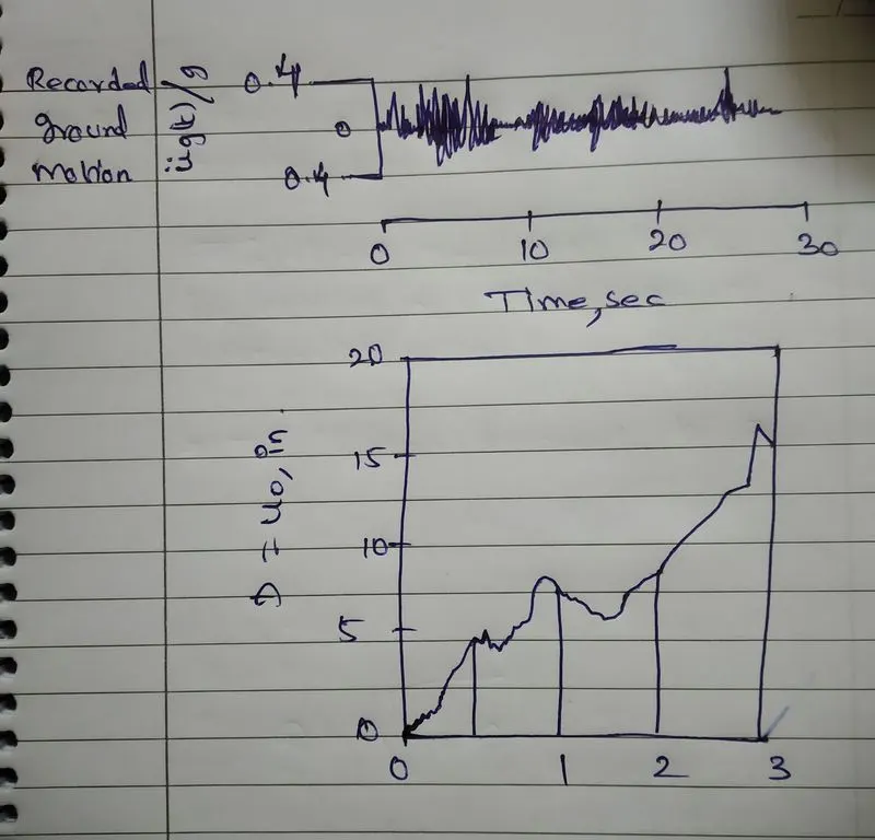
A plot of the peak value of a response quantity (u, v, and a) as a function of the natural vibration period T, of the system, is called the response spectrum for that quantity.
Each such plot is for SDF systems having a fixed damping ratio and several such plots for different values of are included to cover the range of damping values encountered in actual structures.
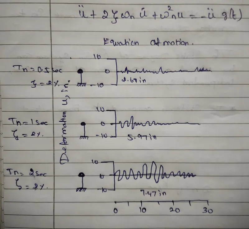
The response spectrum can be of 3 types. The deformation response spectrum is a plot of peak u, against T, for fixed Z. A similar plot for peak ú, is the relative velocity response spectrum, and for peak ûT, is the acceleration response spectrum.