Sketch a G+1 residential plan according to Vaastu Shastra and Calculation of Loads as per IS code
Aim:
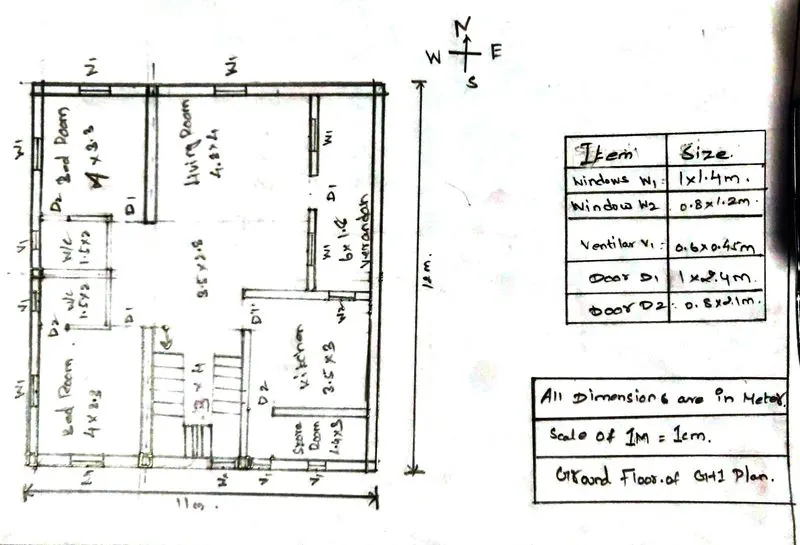
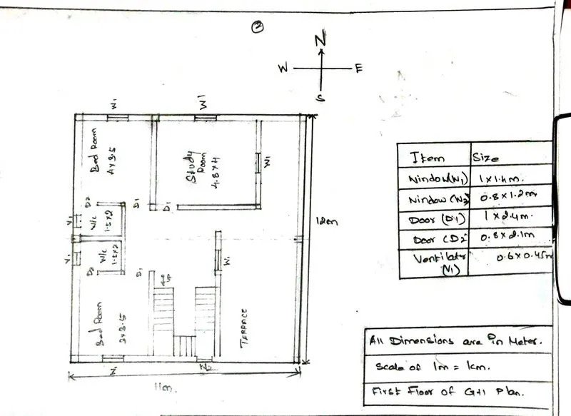
To draw a G+1 floor residential plan according to the vaastu shastra and the essential structural drawing needed to be provided to the site for construction.
Introduction:
- Vaastu shastra is the ancient science of architecture and acts as a guideline to design a home in the way that enhances positive energy.
- A good home needs to radiate right kind of energy. A person dwelling in a house comes under the influence of specific energy field which intern influences him.
- Vaastu shastra and ancient science propounds such theory based on direction, architecture, astronomy and even astrology.
Therefore, it is very crucial to understand the link between the healing act of vaastu and our homes in spreading positivity and good vibes.
- Basic principles of vaastu shastra:
- Shape: Rooms should be preferably square or rectangle.
- Room basics: Rooms should be airy, well lit, bright and clean.
- Home center: Centre of the house should be an empty space.
- Stairs and furniture: Heavy furniture should be kept in southwest direction.
- Water: Avoid keeping plants and water feature in the bedroom.
- Dining table: Dining space should be near the kitchen and not near the main door.
- Mirror placement: Mirror facing beds is strictly not allowed. Mirrors in bedroom should be placed in such a way that the bed cannot be seen.
Procedure:
- G+1 floors residential plan is given below.
- Structural drawings that are to be delivered to site for construction includes:
- Centerline drawing.
- Footing and column layout with reinforcement details.
- Column schedule with reinforcement details.
- Plinth beam layout with reinforcement details.
- First floor beam layout with reinforcement details.
- First floor slab layout with reinforcement details.
- These abovementioned drawings will assist the site engineer to carry out the construction process in a systematic manner.
Result:
- G+1 floors residential plan is drawn by following the basic principles of vaastu shastra.
- The list of drawings that is required for the systematic progress of construction work is also mentioned.
CALCULATION OF LOADS ON THE STRUCTURAL MEMBERS
Aim:
- To calculate the load coming on a structural members like column, beam, slab and walls.
Introduction:
- Structural loads are forces applied to the structural components and are important considerations in the design of buildings
- Loads causes stresses, deformations and displacements in the structure.
- Assessment of these is carried out by structural analysis.
- Excess load may cause structural failure.
- Building codes require structure to be built to safely resist all the forces during their service life.
- Structural loads are split according to their originating cause into dead load and live load, particularly in safety calculations.
- To meet the requirements that is, higher design strength than maximum loads, building codes prescribe that for structural design, loads are increased by load factors.
- These load factors are roughly a ratio of theoretical design strength to maximum load executed in service life.
- Indian codes and standards used for design:
- IS456:2000; Revised 2016 for reinforced concrete structures.
- IS857:1987; Revised 2018 (part I) for dead load.
- IS857:1987; Revised 2008 (part II) for live load.
- IS857:1987; Revised 2015 (Part III) for wind load.
- IS1893:2016; (Part I) for seismic load.
- IS13920:1993 for seismic detailing.
Procedure:
Dead load calculation as per IS857:1987(Part I).
- Column:
Assume the size of column as 400mmx300mm
Let the height of the column be 3.6m
So, total volume of column = 0.4x0.3x3.6 = 0.432 m^3.
Unit weight of concrete = 25kN/m^3
Hence, the dead load of the column = 25x0.432 = 10.8kN per floor.
- Beam:
Assume the cross section of beam as 300mmx450mm.
the area of cross section = 0.3x0.45 = 0.135m^2.
Unit weight of concrete = 25kN/m^3.
Hence, the dead load of beam = 25x0.135 = 3.375kN/m.
- Slab:
Assume the thickness of slab as 200mm.
Considering an area of slab as 1m^2.
Unit weight of concrete = 25kN/m^3.
Hence, the dead load of slab = 25x0.2 = 5kN/m^2.
- Wall:
Thickness of the wall is 230mm.
Height of the wall is 3.6m.
Unit weight of brick masonry is 20kN/m^3.
Hence, the dead load of wall = 20x3.6x0.23 = 16.56kN/m (for ground floor).
Live load calculation as per IS857:1987 (Part II)
For residential buildings, live load values are given as follows:
|
Dwelling house |
Uniformly distributed load (UDL), (kN/m^2) |
Concentrated load (kN) |
|
1. All rooms and kitchen |
2.0 |
1.8 |
|
2. Toilet and bathrooms |
2.0 |
- |
|
3. Corridors, passages, staircases including the tire escapes and store rooms |
3.0 |
4.5 |
|
4. Balconies |
3.0 |
1.5 per metre run concentrated at the outer edge. |
Wind load calculation as per IS857:1987 (Part III)
According to the code, it is necessary to calculate the wind load only if the height of the building exceeds 10m. Here, the height of the building is 7.2m, which is less than 10m. Hence there is no need of calculating the wind load.
Result:
Dead load calculated as per the code, IS857:1987 (Part I) is obtained as follows:
- The dead load of the column = 10.8kN per floor.
- The dead load of the beam = 3.375kN/m.
- The dead load of the slab = 5kN.
- The dead load of the wall = 16.56kN/m.
Live load for a residential building is obtained from Table 1: Imposed loads for different occupancies; of IS857:1987 (Part II)
Wind load is calculated as per the code IS857:1987 (Part III). Since, the height of the building does not exceds 10m, it is not calculated.