Structural dynamics
Static and dynamic analysis are two important techniques used in FINITE ELEMENT ANALYSIS (FEA).
Static Analysis
Systems or bodies that are in a perfect state of equilibrium can be studied using static analysis.
Such a component, body, or system must have zero acceleration (no motion) and no loading that changes with time.
The simplest way to think of static analysis is a simple system where your load is applied and will never change. It is constant and therefore static.
Examples of Static analysis applications:
The most frequent form of finite element structural analysis is static stress analysis. The component or assembly is put through a number of loads and the resulting stress, strain, and deformation are analysed to determine the design’s chances of failure.
Here are some examples of static analysis:
- Bridge design
- Vehicle frames
- Mounting brackets
- Housing design
In the above simulation types, the loads applied are of steady state and constant magnitude.
Dynamic Analysis
The three primary types of dynamic analysis needed in product design are:
Frequency Analysis (Takes place in the frequency domain)
Transient Analysis (Takes place in the time domain)
Random Response Analysis (Input fits no simple pattern)
With dynamic analysis, time is a factor, and loads changing with respect to time must be calculated using dynamic analysis.
Inertial loads due to acceleration, for example, must be modelled using dynamic analysis. Alternatively, if the loads are not in the time domain, they can also be in the frequency domain for dynamic analysis.
Examples Of Dynamic Analysis Applications:
If a load is applied to a system, body, or component with a vibratory or sinusoidal input, then it is probably dynamic and dynamic analysis should be used.
Similarly, if a load is generated by an impact or a collision, it is dynamic.
Here are some examples of dynamic analysis applications:
- Impact analysis
- Component drop test analysis
- Vibrational analysis (although you should use modal analysis here)
- Buckling analysis
When Should You Use Dynamic or Static Analysis?
- Static analysis is far less time-consuming and simpler than dynamic analysis, but what type of analysis should you choose for your application?
- A vast number of simulations can be completed using static analysis, even if there are some brief time or frequency influences at the time of load application.
- Many engineers will opt for a static solution as it is fast, and the cost involved regarding time and software is much higher for dynamic analysis.
- However, if your application involves a time or frequency component, such as an impact test, a dynamic analysis should be used.
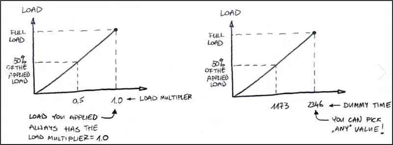
- It is possible to use what is called the “Static Assumption” which assumes that all loads are gradually applied until they reach a full magnitude.
- Using a static load equivalent, it is possible to complete a static analysis (where a dynamic is needed) and increase your load by an additional factor to consider the dynamic loading.
- However, if you use a static analysis where a dynamic is appropriate, even if the initial loads to the system are vibratory or short, you must always check against a dynamic solution.
- A static run might be great to debug, check your mesh and model setup, but a dynamic problem should always be solved with a dynamic analysis.
Summary of Static and Dynamic Analysis
Static Analysis
- Used to calculate stress, strain, and deformation under constant loads
- Generally faster and simpler than dynamic analysis
- May not be as accurate for problems involving time or frequency
Dynamic Analysis:
- Used to calculate stress, strain, and deformation under time-varying loads
- More accurate than static analysis for problems involving time or frequency
- May be more complicated and take longer to run
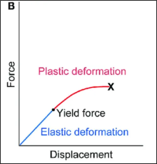
- Elastic Behavior
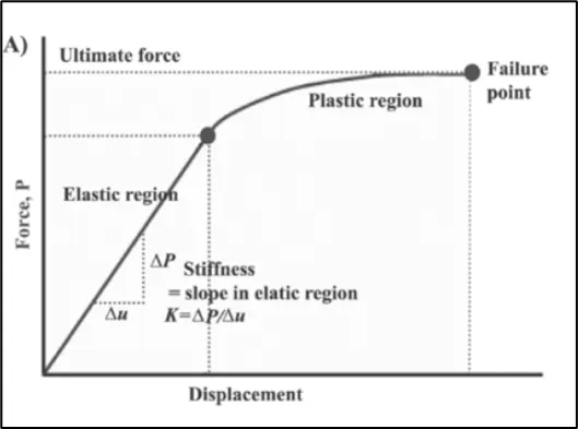
- Elasticity is the ability of a body to resist any permanent change to it when stress is applied. When stress application ceases, the body regains its original shape and size. Different materials show different elastic behavior. The study of the elastic behavior of a material is of much importance.
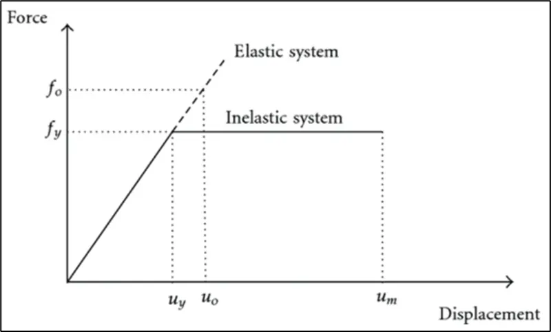
Inelastic Behavior
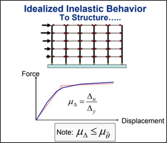
- Deformation of a material that does not disappear on removal of the force that produced it
Plastic behavior:
- For stresses beyond the elastic limit, a material exhibits plastic behavior. This means the material deforms irreversibly and does not return to its original shape and size, even when the load is removed. When stress is gradually increased beyond the elastic limit, the material undergoes plastic deformation.
Non-linear Inelastic behavior :
- Materials have elastic behavior usually only up to a certain load, which is called the 'yield point'. After that, the deformations are plastic. Rubber, for instance, has an elastic stress–strain curve, but the relation is not linear − in such cases nonlinear elastic models are required.
3.Explaination of Mass Stiffness Damping components in equation of motion:
Mass: Newton's second law, which states that the force F acting on a body is equal to the mass m of the body multiplied by the acceleration a of its Centre of mass, F = ma, is the basic equation of motion in classical mechanics.
Mass is always constant for a body. One way to calculate mass: Mass = volume × density. Weight is the measure of the gravitational force acting on a mass.
Stiffness: Stiffness relates to how a component bends under load while still returning to its original shape once the load is removed. Since the component dimensions are unchanged after load is removed, stiffness is associated with elastic deformation. A material can have high strength and low stiffness.
Damping: Damping is a reduction in vibration over a period of time. Damping will eventually bring a vibrating object to rest. A damping mechanism suppresses vibrations of the structure.
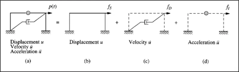
In this section the governing equation for the idealized one-story frame is formulated based on an alternative viewpoint. Under the action of external force p(t) the state of the system is described by displacement u(t), velocity u̇(t), and acceleration ü(t); the system as the combination of three pure components:(1) the stiffness component: the frame without damping or mass (2) the damping component: the frame with its damping property but no stiffness or mass and (3) the mass component: the roof mass without the stiffness or damping of the frame. The external force fs on the stiffness component is related to the displacement u by Eq. fs = Ku if the system is linearly elastic, the external force fd on the damping component is related to the velocity u̇ by Eq. fd = cu̇, and the external force fi on the mass component is related to the acceleration by fi = mü. The external force P(t) applied to the complete system may therefore be visualized as distributed among the three components of the structure, and fs + fd + fi must equal the applied force P(t) leading to Eq. mü+cu̇+ku = P(t)
- Provide relationship between Natural period (Tn) & Natural frequency (f) and provide their definitions
Natural period: The natural period of a building is simply a time taken by it to undergo one complete cycle of oscillation. The natural period is one of the properties or building which is controlled by mass and stiffness.
The time period of a building is its natural period of oscillation when subjected to ground shaking in the event of an earthquake.
The building is modelled to be under harmonic oscillation and the time period is calculated in a similar way as in harmonic oscillation
T = 2π√(k/m)
where k is the total stiffness and m is the total mass.
k is calculated as the sum of the lateral stiffness of all stiffness providing and moment resisting vertical members (columns, moment resisting frames, sheer walls, etc.) m is calculated as the sum of masses of all members on the Story.
[ Note: The above method is only applicable for single Story buildings and for multiple Story buildings, these are vector quantities depending on the mode of vibration. A detailed vector analysis (modal analysis) is done to calculated time periods for each vibration mode, which requires detailed explanation.]
IS 1893 part I lists empirical formulae for approximate estimation of time period of multi-Story buildings given in section 7.6 on page 24.
Natural Frequency: A natural frequency is defined as that frequency at which a body will vibrate if excited by an external force.
The frequency is nothing but the number of vibrations in a second and is the inverse of the time period
f = 1/T
5.Explain in detail about Response spectrum & its Graph (25 marks)
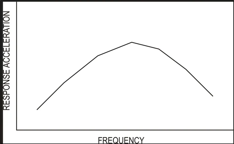
The typical earthquake ground motion response spectrum represents an envelope of the peak responses of many single-degree-of-freedom (SDOF) systems with different periods. The acceleration response spectrum of a ground motion is a relationship between the natural period of vibration of a SDOF system and the maximum absolute acceleration that it experiences under the ground motion. Similarly, a displacement response spectrum typically represents the peak displacement, relative to the ground, of many SDOF systems with different periods. Hence, the construction of a response spectrum involves the analysis of many different SDOF systems. The value of each point on the spectrum is the peak response of a single degree of freedom system of a given period.