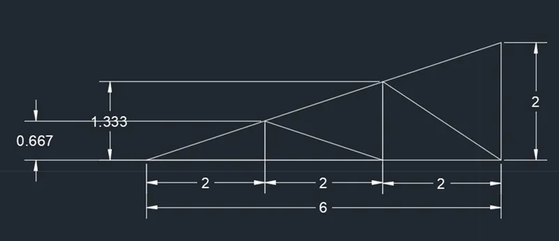
Creation of geometries by Coordinate system methods using AutoCad
1]
1.AIM & INTRODUCTION: TO DRAW THE GIVEN DWG IN PROCEDURE
2.PROCEDURE IN DETAIL:
- Select the line tool by entering line command in the command tab
- Specify the starting coordinate points and draw the full drawing as per commands
- Click close on the command line to finish the drawing.
3.RESULT:
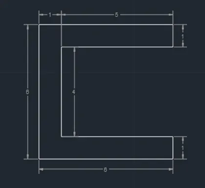
2]
1.AIM & INTRODUCTION: TO DRAW THE GIVEN DWG IN PROCEDURE
2.PROCEDURE IN DETAIL:
- Select the line tool by entering line command in the command tab
- Specify the starting coordinate points and draw the full drawing as per commands
- Click close on the command line to finish the drawing.
3.RESULT:
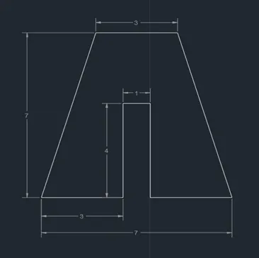
3]
1.AIM & INTRODUCTION: TO DRAW THE GIVEN DWG IN PROCEDURE
2.PROCEDURE IN DETAIL:
- Select the line tool by entering line command in the command tab
- Specify the starting coordinate points and draw the full drawing as per commands
- Click close on the command line to finish the drawing.
3.RESULT:

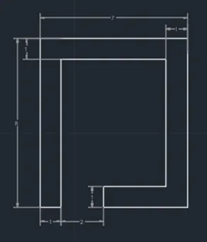
4]
1.AIM & INTRODUCTION: TO DRAW THE GIVEN DWG IN PROCEDURE
2.PROCEDURE IN DETAIL:
- Select the line tool by entering line command in the command tab
- Specify the starting coordinate points and draw the full drawing as per commands
- Click close on the command line to finish the drawing.
3.RESULT:
5]
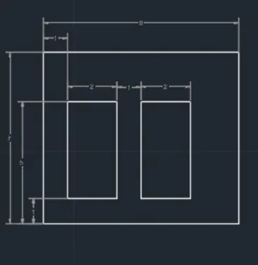
1.AIM & INTRODUCTION: TO DRAW THE GIVEN DWG IN PROCEDURE
2.PROCEDURE IN DETAIL:
- Select the line tool by entering line command in the command tab
- Specify the starting coordinate points and draw the full drawing as per commands
- Click close on the command line to finish the drawing.
3.RESULT:
6]
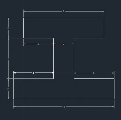
1.AIM & INTRODUCTION: TO DRAW THE GIVEN DWG IN PROCEDURE
2.PROCEDURE IN DETAIL:
- Select the line tool by entering line command in the command tab
- Specify the starting coordinate points and draw the full drawing as per commands
- Click close on the command line to finish the drawing.
3.RESULT:
7]
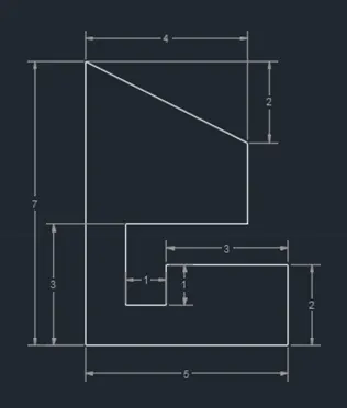
1.AIM & INTRODUCTION: TO DRAW THE GIVEN DWG IN PROCEDURE
2.PROCEDURE IN DETAIL:
- Select the line tool by entering line command in the command tab
- Specify the starting coordinate points and draw the full drawing as per commands
- Click close on the command line to finish the drawing.
3.RESULT:
8]
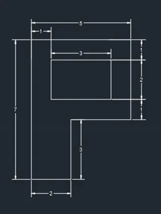
1.AIM & INTRODUCTION: TO DRAW THE GIVEN DWG IN PROCEDURE
2.PROCEDURE IN DETAIL:
- Select the line tool by entering line command in the command tab
- Specify the starting coordinate points and draw the full drawing as per commands
- Click close on the command line to finish the drawing.
3.RESULT:
9]
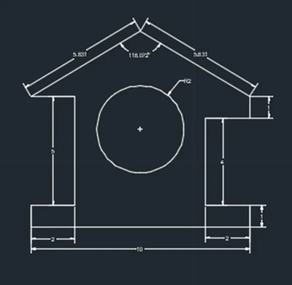
1.AIM & INTRODUCTION: TO DRAW THE GIVEN DWG IN PROCEDURE
2.PROCEDURE IN DETAIL:
- Select the line tool by entering line command in the command tab
- Specify the starting coordinate points and draw the full drawing as per commands
- Specify the circle command in the command tab and draw the circle by mentioning radius or diameter.
- Specify the angle command in command tab to draw the slope line and mention the angle of the slope to draw it.
- Click close on the command line to finish the drawing.
3.RESULT:
10]
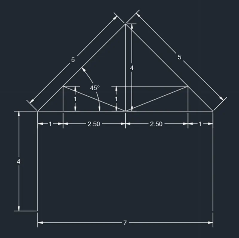
1.AIM & INTRODUCTION: TO DRAW THE GIVEN DWG IN PROCEDURE
2.PROCEDURE IN DETAIL:
- Select the line tool by entering line command in the command tab
- Specify the starting coordinate points and draw the full drawing as per commands
- Specify the angle command in command tab to draw the slope line and mention the angle of the slope to draw it.
- Click close on the command line to finish the drawing.
3.RESULT:
11]
1.AIM & INTRODUCTION: TO DRAW THE GIVEN DWG IN PROCEDURE
2.PROCEDURE IN DETAIL:
- Select the line tool by entering line command in the command tab
- Specify the starting coordinate points and draw the full rawing as per commands
- Specify the angle command in command tab to draw the slope line and mention the angle of the slope to draw it.
- Click close on the command line to finish the drawing.
3.RESULT: