Structural analysis of a buidling using Robot Structural Analysis
1) What are HVAC systems? Why are they essential in the modelling of buildings
ANSWER: -
HVAC SYSTEMS
- HVAC STANDS FOR Heating, ventilation, and air conditioning. HVAC systems are more used in different types of buildings such as industrial, commercial, residential and institutional buildings.
- An HVAC system combines the process es of heating, cooling and air ventilations using a thermostat and other devices thus doing so enables the proper circulation of air inside the building. It also helps in modifying the building temperature according to the needs of the climate or season.
- Basically, the HVAC system means the various systems and types used for moving air between different indoor and outdoor spaces.
- HVAC systems ensure the air quality of the building from residential building like houses and apartment to commercial building like office and hospitals all use an HVAC system.
HVAC essential to modelling of building
- Whenever we are working on a team project or in a real world, we will be given a design requirement of HVAC.
- When we are working on a coordinate project it is necessary to have a basic knowledge of HVAC system which makes us to coordinate with a better judgement.
- While we are modelling it is necessary to look after the comfort’s energy saving of the building. HVAC system are used for controlling the overall climate in the building
- To provide optimum lighting and air circulation and control the temperature and humidity with in the building space. HVAC improves air quality in the building helping make it appropriate for human breathing .it reduces humidity so occupants can enjoy the better atmosphere. This is especially useful for buildings or underground spaces where ventilation is limited.
- For sizing of systems. To check the mechanical performance of the ducts to design them as per space required as per the space allotted to building provisions. This HVAC system place and an important role in the building modelling and they are essential.
2) From week 7 assignment, based on the building designed use the same Revit file to design a HVAC system for each floor to cover the topics included in the class.
- Typical HVAC unit includes Distribution center
- Collector
- Ducts
- Blower
Based on the layout choose appropriate ducts and elevation using property browser and assign the components to appropriate groups to complete modelling of the HVAC unit
AIM: - To create a HVAC system for project 02 which is also 7th week challenge.
INTRODUCTION: - HVAC stands for heating, ventilation and air conditioning. HVAC refers to the different systems used for moving air between indoor and outdoor areas along with heating and cooling both residential and commercial building. They are the systems that keep you warm and cosy in the winter and feeling cool and fresh in the summer.
PROCEDURE: -
- Open Revit 2023.
- Click New from Models.
- So choose the template file Mechanical Template.
- Create New Project
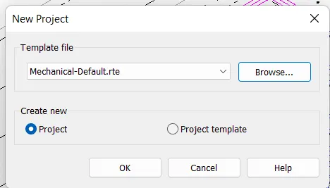
- After opening the mechanical template, now we have to link the architectural file
- Go to the Insert tab, and click on link Revit to link the architectural file into the mechanical template
- Then manage the architectural file by clicking on manage links in the manage tab
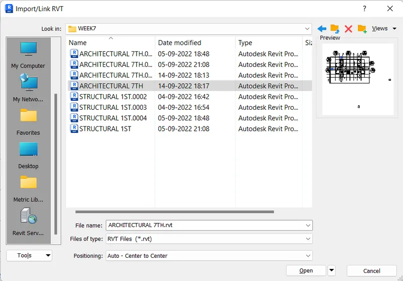
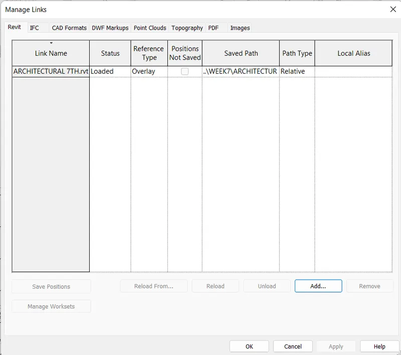
- After Linking the architectural file, now we have to save the file with the HVAC System
- Go to the File option, Click the save option and give the file name as "Mechanical template "
- Now go to the System tab, and select the Air terminal to
- Select the Air terminal tool as a Supply diffuser from the Project browser
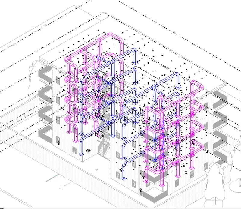
- Place the Air Terminals in the required location as shown in the figure below
- Now go to the system tab again, and select the mechanical equipment option
- In that tab, select the loaded family option to load the various mechanical systems
- Select the Air handling unit from the libraries and load it into the Revit
- Select the Air handling unit and place it in the desired location as shown in the figure below
- Now we need to make the duct layout for the components
- Select all the mechanical components that we placed on the plan
- After selecting the components, select the Duct tool in the ribbon tab
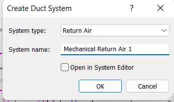
- It will create the duct system and then press ok to create the connector
- After creating the connector, click on Generate Layout in the ribbon tab
- Select the layout from the various layouts options and click finish layout
- Similarly for same procedure for other connection also
- After creating the HVAC layout on the first floor, we have to copy it to the other floors
- Select all the mechanical components and copy it
- From the ribbon tab, select the paste option and paste it through the aligned levels as shown in the figure below

RESULT: -
The HVAC system has been designed successfully for each floor of the architectural building.
3) Use the add-ins tab to load plug-ins for robot structural analysis to your Revit software
AIM: - To load plugins for robot structural analysis to Revit software using the add-ins tab
INTRODUCTION: - Robot Structural Analysis Professional is structural load analysis software that verifies code compliance and uses BIM-integrated workflows to exchange data with Revit. It can help you to create more resilient, constructible designs that are accurate, coordinated, and connected to BIM.
Autodesk Robot Structural Analysis hosts a range of powerful FEM solvers enabling structural engineers to conduct complex calculations such as modal, harmonic, spectral, dynamic, non-linear, footfall analysis, and many more.
This comprehensive structural engineering design software solution allows enhanced BIM operability both within the AEC collection and other software enabling engineers to iterate and optimize their designs with full communication between packages ultimately streamlining the design process and allowing traceability of design changes along the way.
PROCEDURE: -
The primary procedure for invoking or installing the ROBOT structural analysis tool is from the cart option from the Revit itself, but in this we do it from the Autodesk official site because it cannot appear in the cart from the Revit
- open the chrome browser in your desktop
- the search AUTODESK.com
- then official Autodesk official website is open
- then we have search option in Autodesk site also
- click on search -"ROBOT structural analysis "
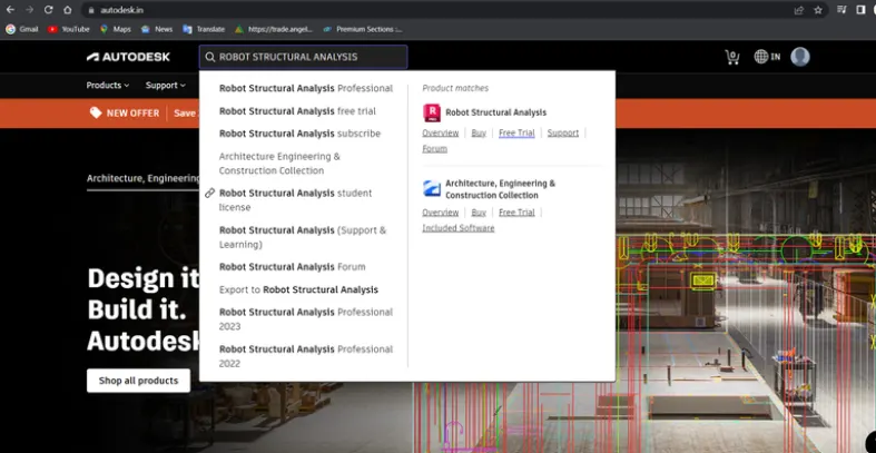
- then we have a "free trial " option on the screen of Autodesk
- click on that and installed it
- Click on next

- And give the details and click on begin download.
- After download install.
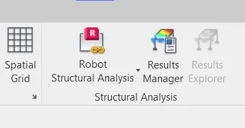
- After installing it appears in analyze tab
- It also appears on the desktop.
RESULT: - Added the robot structural analysis to the Revit software
4) Why do we need to assess buildings/analyze while modelling elements? Does design affect modelling in anyways?
ANSWER: -
- The main reason behind analyzing is when we create anything we just take the sizes of each component as we seem a best fit only from the architectural point of view.
- We never think while designing that will it carry those high loads? So when we analyze the building by adding the loads to it and check whether the building will sustain those loads or not.
- The analyzing tool helps us to determine the safety of the building.
- For example, would you ever find yourself in a situation where you cook food for someone and serve it to the people without tasting it? We surely will taste it to know if it's good or not.
- Similarly, before constructing the building we need to analyze if it will be able to overcome all kinds of loads which will be acting on it.
- Thus, analyzing helps us to cross-check the whole structure of the building and to determine whether the building is safe for utilization or not in the real world!
- If we do not analyze the structure, we would never know how safe it is.
- It will be always a threat to life.
- Just in case a building is constructed without analyzing its structure then there is a possibility that the structure might fail all of a sudden.
- This will cost a lot of lives of the people and many other living creatures.
5) From the structural model developed in week 6 and 7, export the complete analytical model to robot structural analysis.
- List your assumptions on what boundary conditions will be realistic for the analysis approach
- Use the design standards to decide what loads must be applied to floorings based on the type of structure decided
- List the load combinations and include them in the analysis model
- Analyze the building and report the following results
- Maximum Moment in each floor for all Load Combinations
- Maximum Displacement in each floor for all Load combinations
- Lateral Displacement in building for all Lateral Load combinations
e . After analysis, do you think you have a better approach or idea in modelling structural members?
AIM: - To export the complete analytical model to robot structural analysis from the structural model.
INTRODUCTION: - The analytical model represents a simplified version of the structural descriptive Revit model. Coming together to create an engineering model, the analytical model contains information such as the structural components, the geometry of the structure, cross-section of the structural elements, end conditions, material properties, and loads.
PROCEDURE: -
- First Open the Structural model that we developed in weeks 6 and 7
- Then go to analyze tab, to analytical automatic then get the analytical model of structure
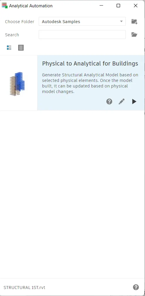
- Then play that option which appeared in
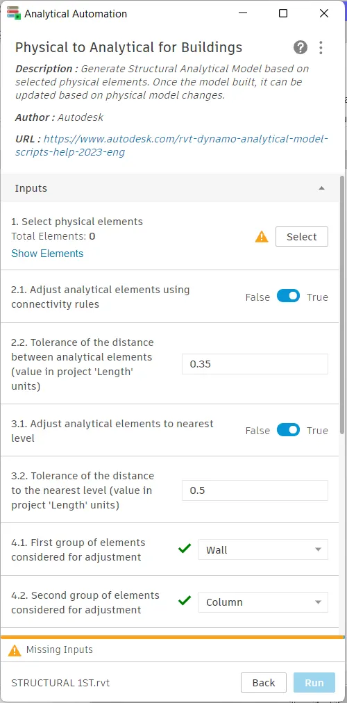
- Then select the Revit file by the draging mouse curser
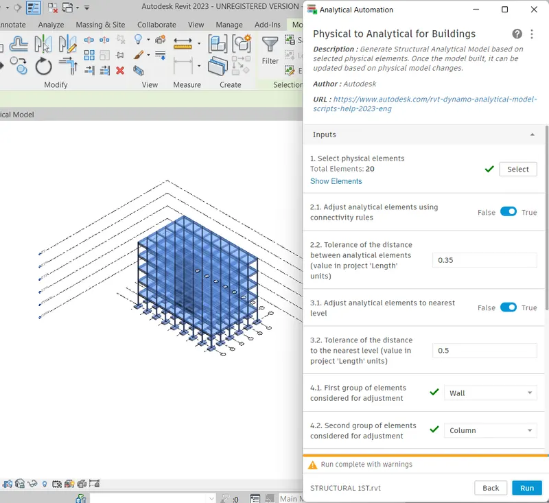
- Then run option for the analytical model of structure
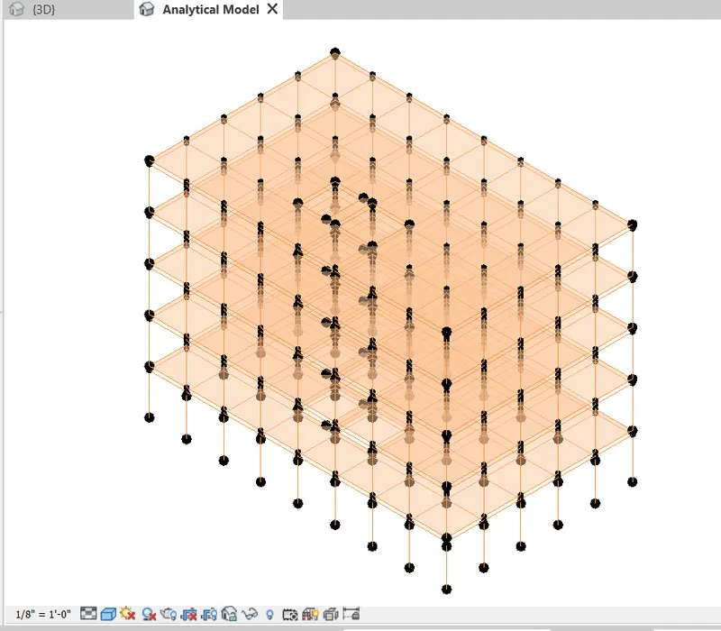
- Then go to analyze tab, to apply the various load cases and combinations
- Go to analyze tab again and select the load case option
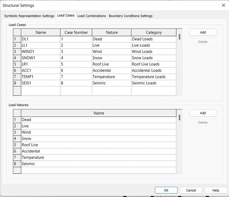
- Add the new load cases using the add option
- Here, I'm selecting the load cases as DEAD LOAD, LIVE LOAD & WIND LOAD
- After assigning the load cases in the dialog box, press okay
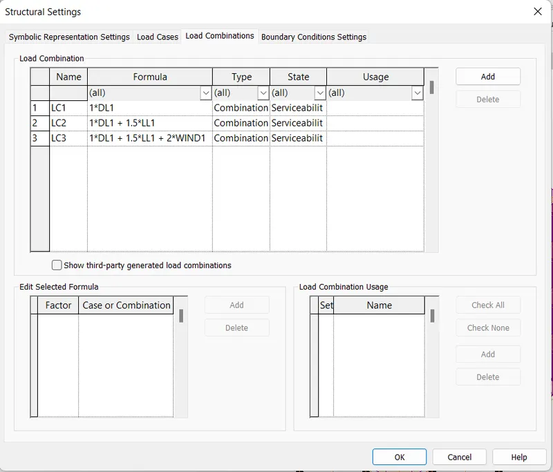
- Go to analyze tab again and select the load combinations option
- Add the new load combination using the add option
- Select the load that we want to apply and give factor as a formula to it
- Here, I'm selecting the load combinations as LC1 = 1.0DL, LC2 = 1.0DL + 1.5LL & LC3 = 1.0DL + 1.5LL + 2.0WL
- After assigning the load combinations in the dialog box, press okay
- In the analyze tab, select the load's tool from it
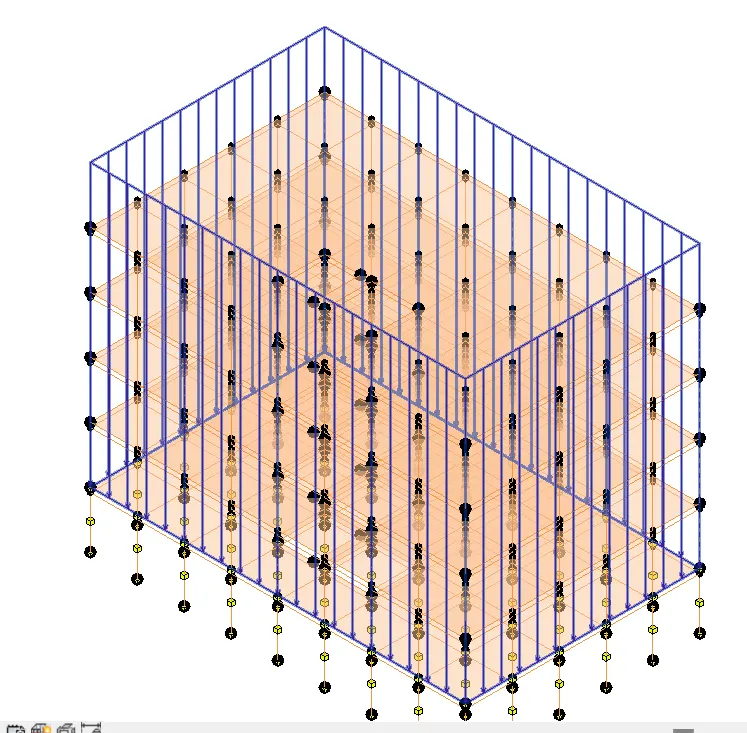
- Then select the Line load option from the loading tool
- The modify tab will appear, select the rectangle tool and sketch the load boundary to all floors
- Similarly apply the area load as shown in the figure below
- After assigning the load cases and load combinations, now we have to assign the boundary conditions to it.
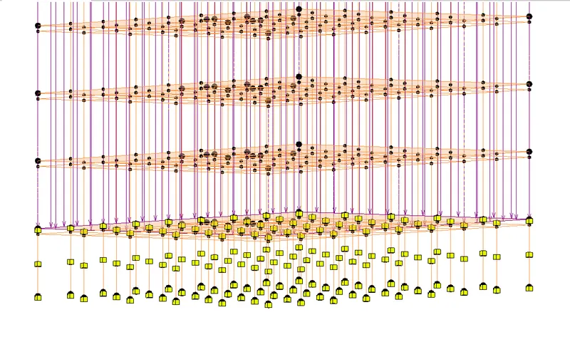
- Select the Boundary Conditions tool from the analyze tab
- We have to apply the boundary conditions in an analytical view only
- Select the boundary condition has to point and then apply the boundary conditions to all the columns
- After assigning all the loads, load cases, load combinations, and boundary conditions now we have to export them into the robot structural analysis
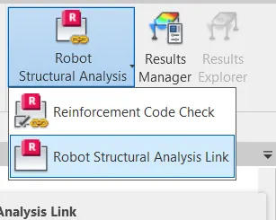
- Select the Robot Structural Analysis from the analyze tab
- Then select the Robot Structural Analysis link and press okay to send the model
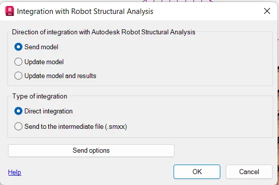
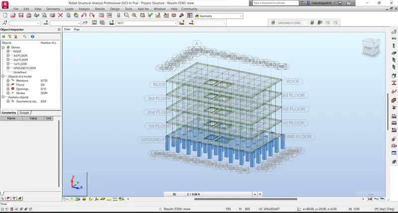
- After sending the model to the robot structural analysis, now we have to see the calculation results
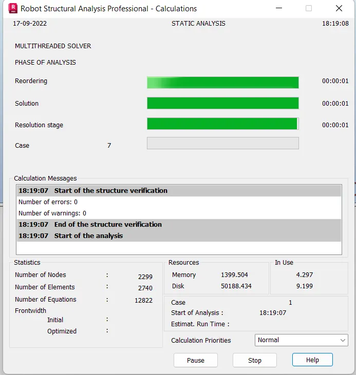
- In the robot structural analysis, go to the results tab and select the diagrams from the member's option
- It will show the Stress and reactions of Fx, Fy and Fz values
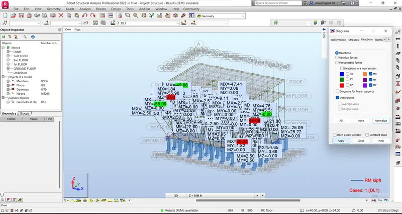
- Select the reactions option from the diagrams tool
- Now we can see the bending moment and shear force values i.e., Mx, My and Mz values
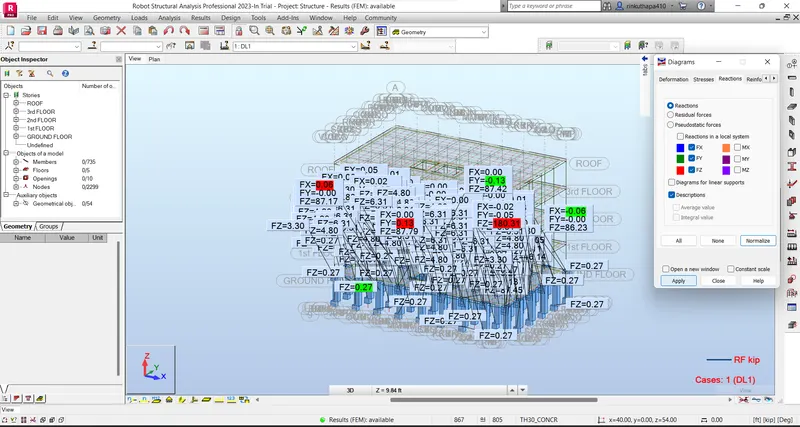
RESULT: - The Analytical model of the structural model that we developed in weeks 6 and 7 has been exported to the robot structural analysis successfully
6) What is energy analysis and why do we need to consider it while modelling in Revit?
How does the factor of sustainability improve the quality of your design?
ANSWER: - Energy analysis is the process of analyzing a building's energy performance by calculating how well the integration of that building's form, systems, and envelope perform under the surrounding environmental conditions.
Four general principles of energy analysis:
- Calculating energy
- Calculating heat loss and gain
- Determining fuel requirement
- Evaluating the costs.
Factor of sustainability improves the quality of design in the following ways:
Sustainable designs look to lower the negative impacts of the construction and also the building throughout its life cycle by implementing
- Low energy consumption.
- Reducing or omitting greenhouse gas emissions.
- Reduced resource consumption or choosing environment friendly alternatives.
- Usage of Nontoxic materials.
- Quality and durability over cost.