Analysis of Steady and Unsteady flow over a cylinder
Objective :-> Simulate flow over a cylinder for study of following parameters-
- Phenomenon of Karman vortex street.
- To obtain Strouhal number at Reynolds number=100.
- To compare `C_d` (drag coefficient) for different Reynolds number.
Theory:-
In fluid dynamics vortex shedding is an oscillating flow that takes place when a fluid flows over body at certain velocities. In such flow over body vortices are created at back of the body and detach periodically from either side of body forming a Von Karman vortex street. Fluid flow past object creates alternating low pressure vortices on downstream side of object.
The following figure shows Vortex street animation.

Vortex shedding frequency is an important parameter in designing because, if the vortex shedding frequency matches with resonance frequency of structure, then structure can begin resonate and failure may occur.
The frequency at which vortex shedding takes place is related to Strouhal number by following equation,
`St=(omegaD)/V`
Where,
`St=` Dimensionless Strouhal number
`omega=` Vortex shedding frequency
`D=` Characteristic length (diameter of cylinder for our condition)
`V=` Free-stream flow velocity
The Strouhal number is important when analyzing unsteady oscillating flow problems. The Strouhal Number represents a measure of the ratio of the inertial forces due to the unsteadiness of the flow or local acceleration to the inertial forces due to changes in velocity from one point to another in the flow field.
Preprocessing:-
Geometry (Surface creation in spaceclaim):

Above geometry shows 2D representation of flow over circular cylinder of 2m diameter placed in uniform fluid flow . The geometry is created in Ansys space-claim. In geometry fluid flow come from left side of cylinder (inlet) which is at distance of 10 times cylinder diameter from cylinder center and leaves from right side of cylinder (outlet) which is at distance of 20 times cylinder diameter from center of cylinder.
Mesh:

Above figure shows meshed geometry, where we have used triangular meshing method. Element size taken for meshing is 0.5m. The number of elements in above geometry are 10814 and number of nodes are 5747. The mesh size is obtained after iterating results.

Above figure shows detailed meshing at cylinder wall, here inflation layer is provided, which capture better visualization and simulation result around cylinder wall. We have provided 8 layers of inflation.
Material:
We have used material of fluid with following properties,
Kinematic viscosity = 0.02,
Density = 1kg/m^3.
Solving:-
For the project we have selected SIMPLE solver.

Post-processing:-
Part I:
Steady state case at Reynolds number = 100:-

Fig:-Plot iterations v/s residuals
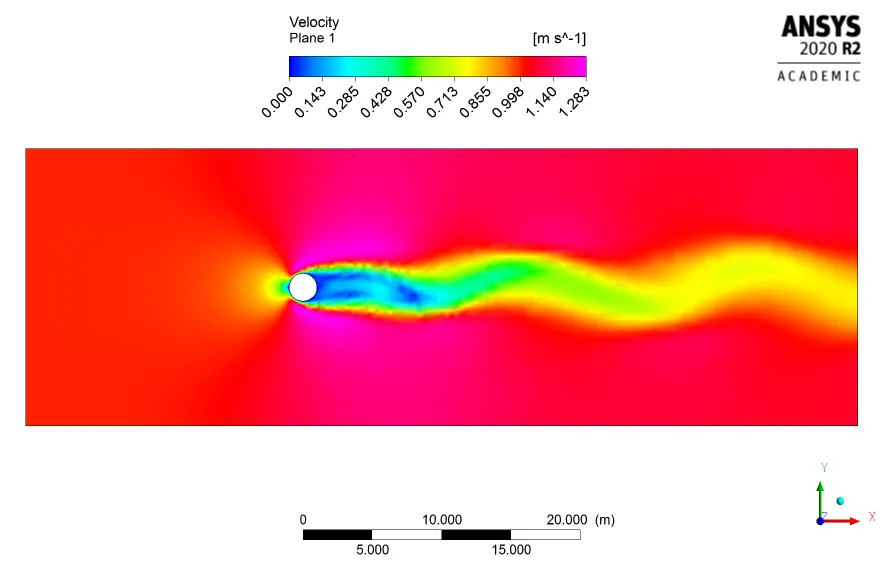

Fig a: Velocity contour Fig b: Pressure contour

Fig:- Velocity at monitor point
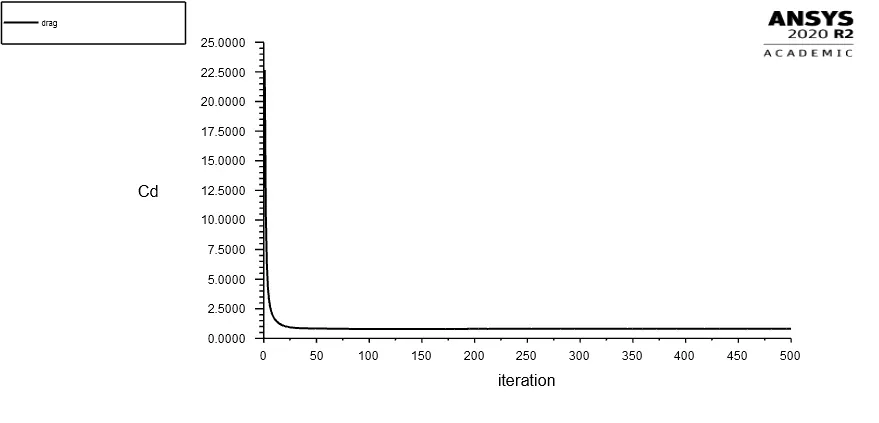

Fig a: Drag coefficient plot Fig b: Lift coefficient plot
Transient state case at Reynolds number = 100:-

Fig:-Plot iterations v/s residuals
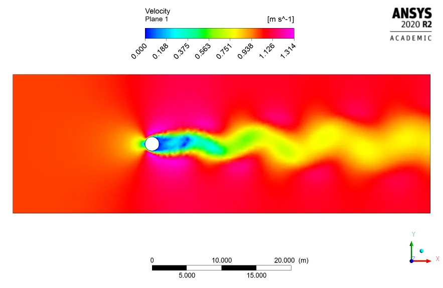

Fig a: Velocity contour Fig b: Pressure contour

Fig:- Velocity at monitor point

Fig:- Velocity flow and vortex creation animation
Above animation shows how Karman Vortex flow is created.
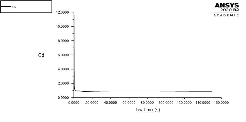

Fig a: Drag coefficient plot Fig b: Lift coefficient plot
For the above transient case, drag coefficient=0.82079358 & lift coefficient=0.059821179.

Fig:- Vortex frequency plot
As per above obtained plot for vortex frequency, we can find that vortex frequency = 0.1Hz.
`omega=0.1Hz`,
Velocity = 1m/s,
Characteristic length = 2m
Hence to calculate Strouhal number,
`St=(0.1xx2)/1`
`:.St=0.2`
Strouhal number cannot be calculated for steady state cases as there is no time dependent parameter which is required to calculate vortex frequency.
Part II:
As we know, Reynolds number is the ratio of inertial force to viscous force.
`Re=(UL)/nu_0`
where,
`U=` Free stream velocity
`L=` Characteristic length of body
`nu_0=` Kinematic viscosity
Hence for manipulating Reynolds number we have changed free stream velocity.
For the laminar viscous flows i.e. Reynolds number less than 2000 we have used laminar solving model and for the turbulent flows i.e. Reynolds number greater than 4000 we have used `k-omega` SST model.
1. When Reynolds number = 10
Free stream velocity U=0.1m/s
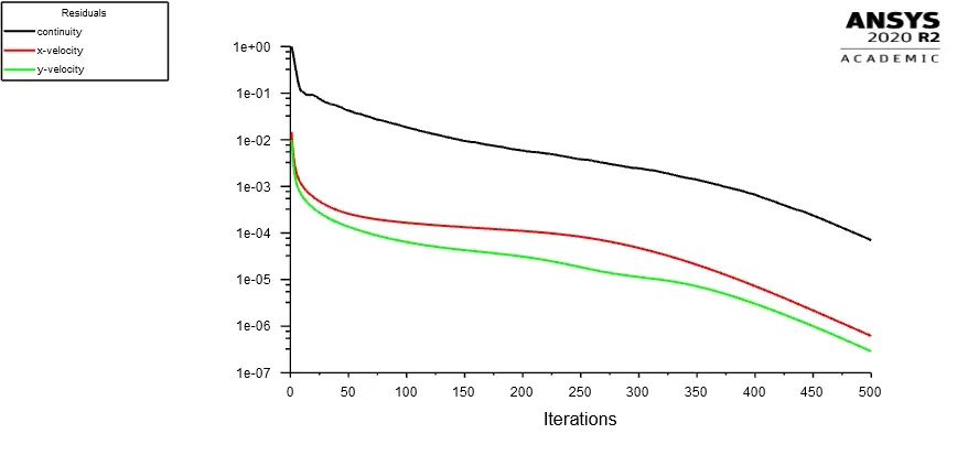

Fig a: Plot iteration v/s residuals Fig b: Velocity at monitor point
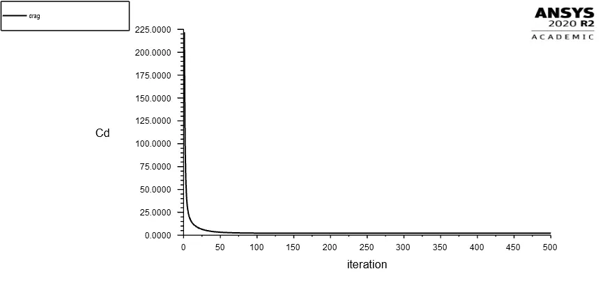

Fig a: Drag coefficient plot Fig b: Lift coefficient plot
2. When Reynolds number = 1000
Free stream velocity U=10m/s
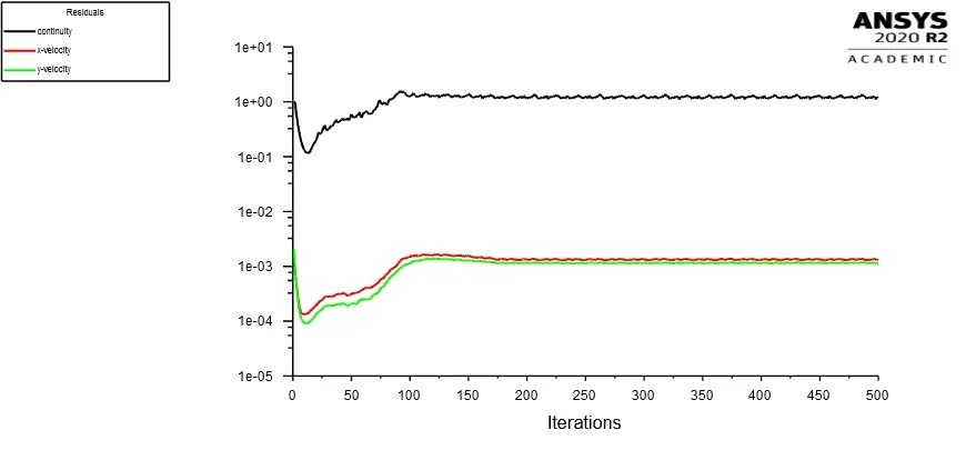
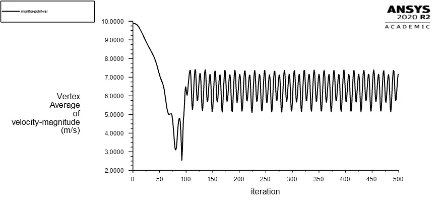
Fig a: Plot iteration v/s residuals Fig b: Velocity at monitor point
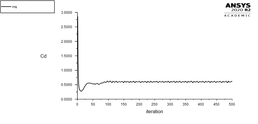

Fig a: Drag coefficient plot Fig b: Lift coefficient plot
3. When Reynolds number = 10000
Free stream velocity U=100m/s
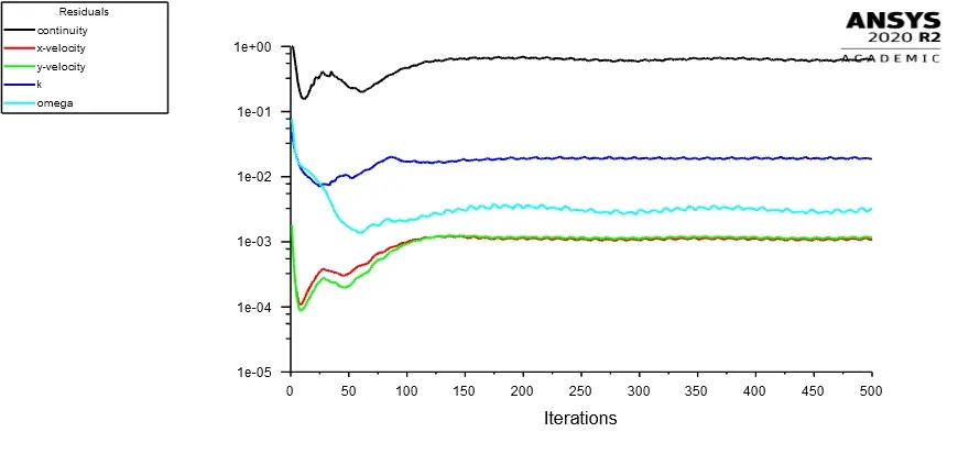

Fig a: Plot iteration v/s residuals Fig b: Velocity at monitor point
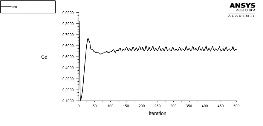

Fig a: Drag coefficient plot Fig b: Lift coefficient plot
4. When Reynolds number = 100000
Free stream velocity U=1000m/s
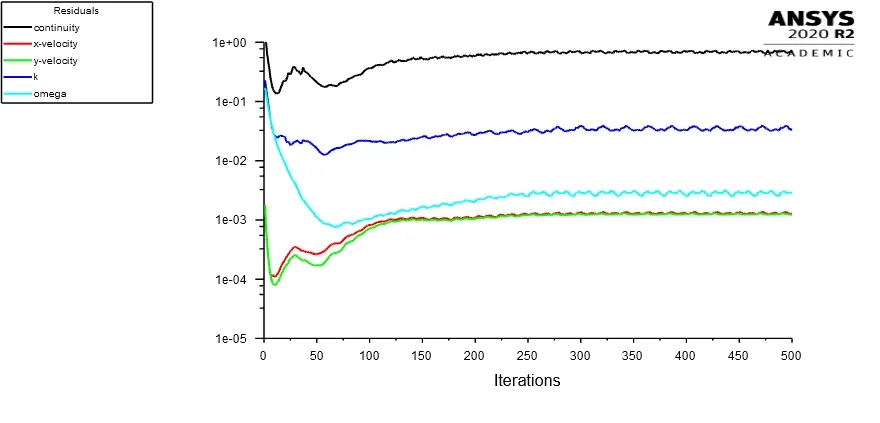

Fig a: Plot iteration v/s residuals Fig b: Velocity at monitor point
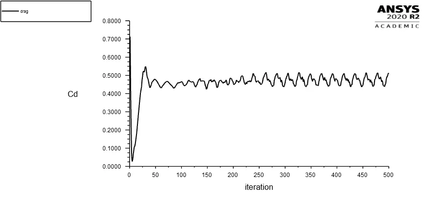

Fig a: Drag coefficient plot Fig b: Lift coefficient plot
Drag Coefficient (Cd):
As per fluid dynamics concerned, drag coefficient is a non dimensional quantity and used to calculate drag i.e. resistance force due to fluid flow on object. The low drag coefficient enables object to move easy in flow i.e. the body experienced very less resistance force in motion, whereas higher drag coefficient caused higher resistance force to body in motion. Drag coefficient depends upon shape of object. It can be calculated as-
`C_d=(2F_d)/(rho.u^2.A)`
Where,
`F_d=` Drag force
`rho=` Density of fluid
`u=` Velocity
`A=` Area of object
As seen in all of the above iterations v/s residual plot, the same pattern is repeating, hence it shows the solution is converged.
From the results obtained above we can see that for Reynolds number =10 there is no Karman Vortex street present, which is correct as per theoretical view. We know as per theory Karman Vortex Street is visible if and only if Reynolds number is greater than 40.
From above plots and obtained result we have tabulated drag coefficient and lift coefficient values below.
| Reynold number | Drag coefficient (Cd) | Lift coefficient (Cl) |
| 10 | 2.112004 | -0.00152278 |
| 100 | 0.811784 | -0.03412374 |
| 1000 | 0.612792 | -0.01971748 |
| 10000 | 0.566588 | 0.065349181 |
| 100000 | 0.508947 | -0.29732024 |
From above summery for better understanding lets plot graph for Reynolds number v/s drag coefficient.
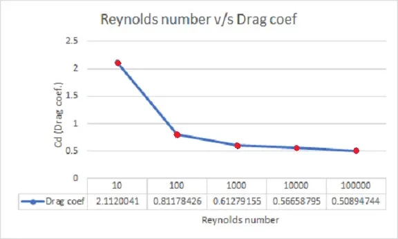
From above figure and tabulated data its clear that with increase in Reynolds number, drag coefficient decreases. And for higher values of Reynolds number there is slight change in drag coefficient as compared to low Reynolds number.
Conclusion:- By referring above obtained results, plots and data we can conclude that-
- For capturing vortex shedding near cylinder wall adding inflation layer is important, it gives more accurate result as number of inflation layer increases but simultaneously takes large simulation time.
- Vortex frequency should not match with resonance frequency of structure.
- Strouhal number is 0.2 for above problem.
- Strouhal number can be only calculated for transient condition.
- Drag coefficient decreases with increase in Reynolds number.
- For Reynold number 10 there is no vortex present.