Solid and Shell meshing along with connection implementation of the car rear suspension model.
Aim- Solid and Shell meshing along with connection implementation of the car rear suspension model.
Abstract- In this project, half part of the suspension system is taken, the model be will checking for geometrical issues, and then 1D,2D,3D meshing to be performed.1D meshing will perform on the spring element and 2D meshing will perform on the part where the thickness is less than 5mm, and then 3D meshing on the rest of the part. Along with meshing, will be implemented as per requirement are.
Methodology- These are the steps going to be followed for his project.
1- Geometry importing and topology cleanup.
2- Assigning the parts in different PIDs.
3- Quality criteria and mesh parameter setup as per requirements.
4- Adjustment of construction line defeaturing.
5- Extraction of mid surface for the parts that having a thickness less than 5mm.
6- Shell meshing of mesh improvement.
7- 1D meshing for spring-like structure.
8- 3D meshing on the rest of the part and defining volume and volume meshing.
9- Implementation of connections.
10- Draw Shell as Solid for thickness assigning for a 2D element.
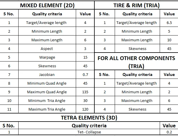
Quality Parameters-
These are the quality parameter to be followed.
Introduction-
Vehicle suspension system-
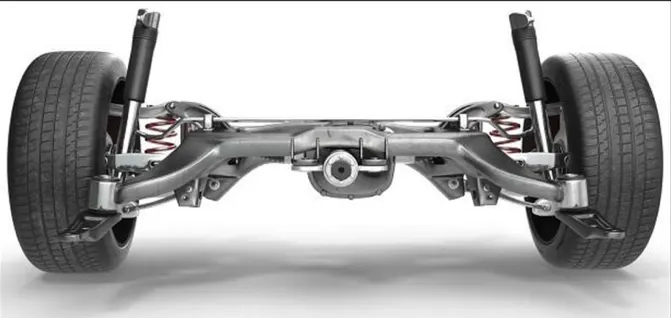
To many focusing on ride comfort, it may seem like the suspension system is merely a set of springs and shock absorbers that connect the wheels to the vehicle body. However, this is a very simplistic view of the suspension system. A vehicle suspension system provides a smooth ride over rough roads while ensuring that the wheels remain in contact with the ground and vehicle roll is minimized. The suspension system contains three major parts: a structure that supports the vehicle’s weight and determines suspension geometry, a spring that converts kinematic energy to potential energy or vice versa, and a shock absorber that is a mechanical device designed to dissipate kinetic energy.
An automotive suspension connects a vehicle’s wheels to its body while supporting the vehicle’s weight. It allows for the relative motion between the wheel and vehicle body; theoretically, a suspension system should reduce a wheel’s degree of freedom (DOF) from 6 to 2 on the rear axle and 3 on the front axle even though the suspension system must support propulsion, steering, brakes, and their associated forces. The relative motions of the wheels are its vertical movement, rotational movement about the lateral axes, and rotational movement about the vertical axes due to the steering angle.
The function of the suspension system-
As previously mentioned, it is mostly assumed that the only function of a suspension system is the absorption of road roughness; however, the suspension of a vehicle needs to satisfy several requirements with partially conflicting aims as a result of different operating conditions. The suspension connects the vehicle’s body to the ground, so all forces and moments between the two go through the suspension system. Thus, the suspension system directly influences a vehicle’s dynamic behavior. Automotive engineers usually study the functions of a suspension system through three important principles.
1- Ride Comfort-
Ride comfort is defined based on how a passenger feels within a moving vehicle. The most common duty of the suspension system is road isolation isolating a vehicle body from road disturbances. Generally, ride quality can be quantified by the passenger compartment’s level of vibration. There are a lot of inner and outer vibration sources in a vehicle. Inner vibration sources include the vehicle’s engine and transmission, whereas road surface irregularities and aerodynamic forces are the outer vibration sources.
2- Road Holding-
The forces on the contact point between a wheel and the road act on the vehicle body through the suspension system. The amount and direction of the forces determine the vehicle’s behavior and performances, therefore one of the important tasks of the suspension system is road holding. The lateral and longitudinal forces generated by a tire depend directly on the normal tire force, which supports cornering, traction, and braking abilities.
3-Handling-
A good suspension system should ensure that the vehicle will be stable in every maneuver. However, perfect handling is more than stability. The vehicle should respond to the driver’s inputs proportionally while smoothly following his/her steering/braking/accelerating commands. The vehicle behavior must be predictable, and behavioral information should accordingly be communicated to the driver. Suspension systems can affect vehicle handling in many ways: they can minimize the vehicle’s roll and pitch motion, control the wheels’ angles, and decrease the lateral load transfer during cornering.
Types of the suspension system-
1- Independent suspension system-
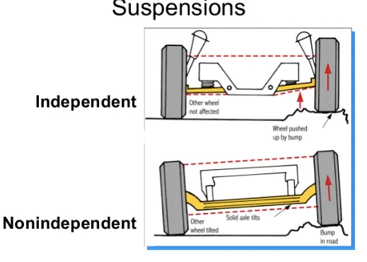
Dependent systems may be differentiated by the system of linkages used to locate them, both longitudinally and transversely. Often both functions are combined in a set of linkages. In a front-engine, rear-drive vehicle, dependent rear suspension is either "live axle" or de Dion axle, depending on whether or not the differential is carried on the axle. Live axle is simpler but the unsprung weight contributes to wheel bounce.
Because it assures constant camber, dependent (and semi-independent) suspension is most common on vehicles that need to carry large loads as a proportion of the vehicle weight, that have relatively soft springs, and that do not (for cost and simplicity reasons) use active suspensions. The use of dependent front suspension has become limited to heavier commercial vehicles.
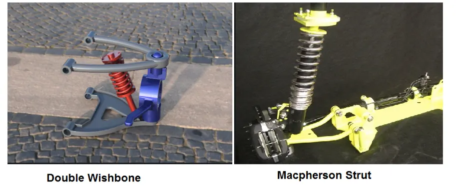
Example of the Independent suspension system-
A- Double Wishbone
B- Macpherson Strut
2- Dependent suspension system-
In this suspension system, the wheels are not constrained to remain perpendicular to a flat road surface in turning, braking, and varying load conditions, control of the wheel camber is an important issue. The swinging arm was common in small cars that were sprung softly and could carry large loads because the camber is independent of load. Some active and semi-active suspensions maintain the ride height, and therefore the camber, independent of load. In sports cars, optimal camber change when turning is more important.
Wishbone and multi-link allow the engineer more control over the geometry, to arrive at the best compromise, than swing axle, MacPherson strut or swinging arm do; however the cost and space requirements may be greater. A semi-trailing arm is in between, being a variable compromise between the geometries of swinging arm and swing axle.
3- Semi-Independent suspension system-
In a semi-independent suspension, the wheels of an axle can move relative to one another as in an independent suspension but the position of one wheel affects the position and attitude of the other wheel. This effect is achieved via the twisting or deflecting of suspension parts under load. The most common type of semi-independent suspension is the twist beam.
Difference between dependent and Independent suspension system-
Components of the suspension system-
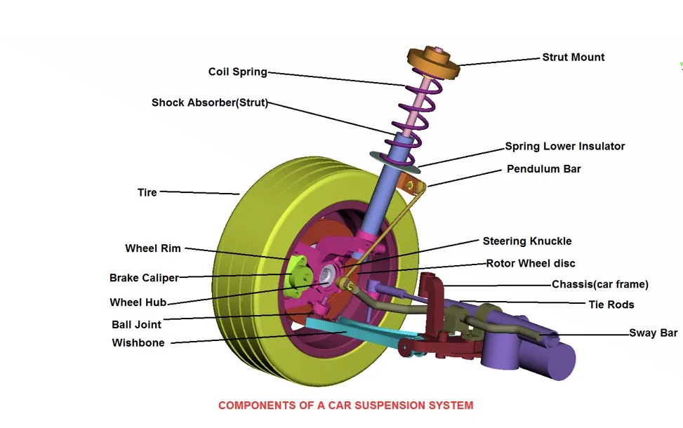
Main parts of the suspension system-
Mechanism-
The suspension mechanism might contain one or several arms that connect a wheel to the vehicle body. They transfer all forces and moments in different directions between the vehicle body and the ground. The mechanism determines some of the most important characteristics of a suspension system. It determines the suspension geometry and wheel angles and their relative motions. Variation in wheel angles during suspension travel causes a change in tire forces, which affect the vehicle’s road holding and handling. The main weight of a suspension system arises from its mechanism. Using heavy materials in its construction decreases the ride quality, whereas light materials, although improve ride quality, are more expensive.
Spring-
The spring is usually a winding wire or several strips of metal that have elastic properties. It supports the vehicle’s weight and makes a suspension tolerable for passengers. To best understand suspension behavior, the most important component requiring study in the spring. However, with its importance, a conflict arises: when using high stiffness springs, the vehicle exhibits good road holding and handling but with a noticeably decreased ride comfort. This creates a condition of limitation when choosing an appropriate spring stiffness. The spring weight and size may also make this accommodation difficult.
Shock Absorber-
The shock absorber is a mechanical or hydraulic device to dampen impulses. A high damping shock absorber compromises the vehicle’s ride quality to immediately dampen impulses to improve handling and road holding.
Bushing-
The bushings prevent the direct contact of two metal objects to isolate noise and minimize vibration. Soft materials such as rubber are used in bushings for isolation. They are a type of vibration isolator used to connect various moving components to the vehicle body or suspension frame. Many types of bushing exist, and they are classified by the number of DOF between the two connected parts that they support. Revolute joints are the most common type of bushings. They are annular cylindrical and support a rotational relative motion, whereas ball joints allow rotational relative motion in all directions. Bushings are some of the most expensive parts of a suspension system.
Procedures-
File Importing and Geometry Cleanup-
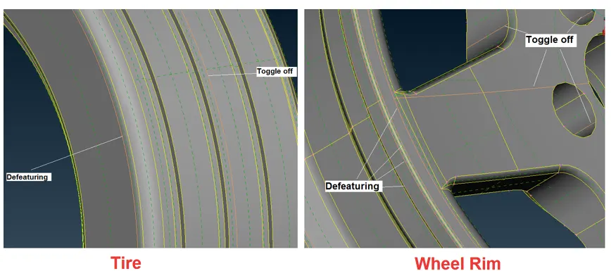
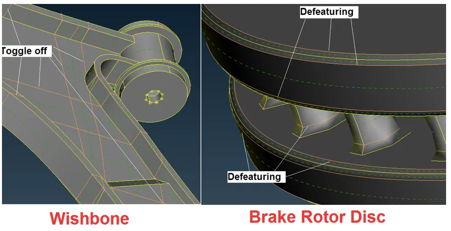
Firstly we need to import the cad file check for any geometry cleanup and apply the topology on the model. There are two ways that we can clean up geometry, first one auto fix, and manual fix by using release the cons and defeaturing the cons.
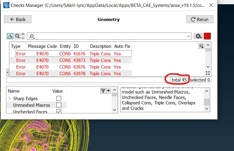
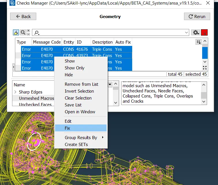
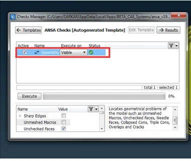
PIDs Assigning-
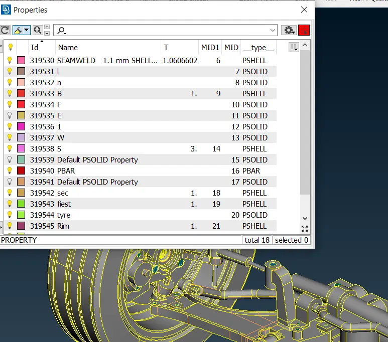
After cleaning up the geometry we can go for PID defining process, PID assigning make the meshing and easy to work on the model. we can work on the model using PID that helps us to work on a part by part.
Quality Criteria Setup-
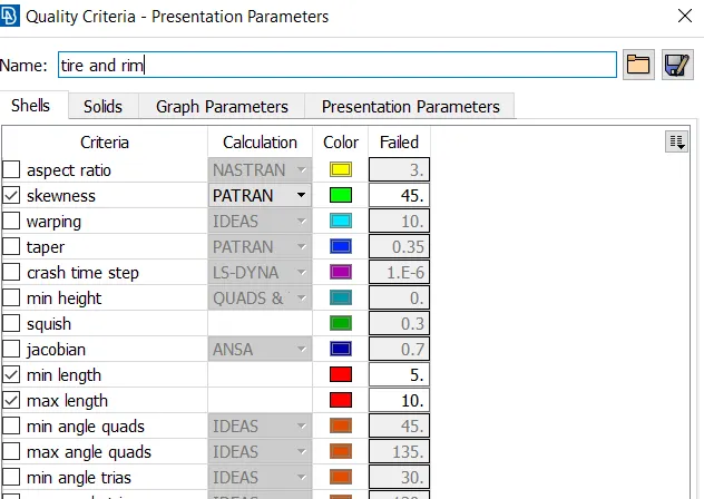
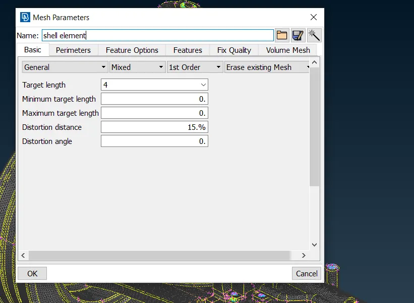
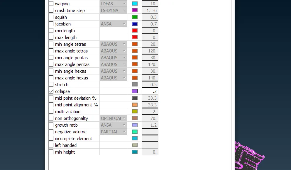
Quality criteria set up are important for meshing which helps with the element-wise meshing quality. Here in this model, there are three types of quality criteria parameters.
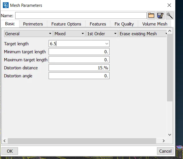
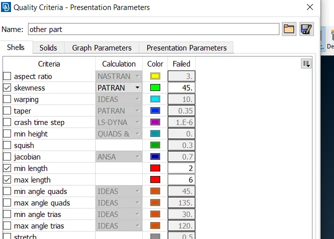
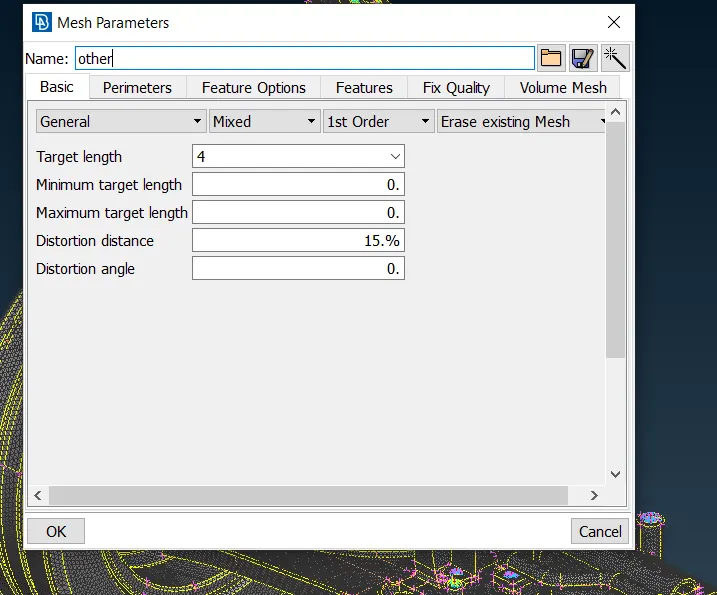
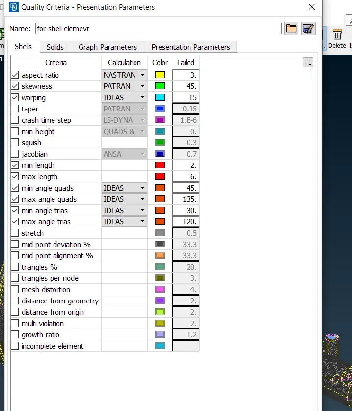
Mid Surface Extraction for part (thickness<5mm) and meshing- ( 2D MESHING)
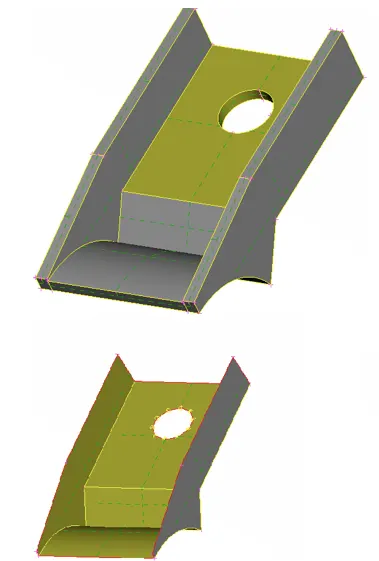
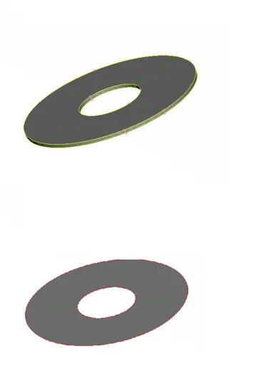
In this model there is the element that has a thickness less than 5mm, so for that, we have to take the mid surface extraction for that part using offset and then we can go for shell meshing using mixed shell meshing.
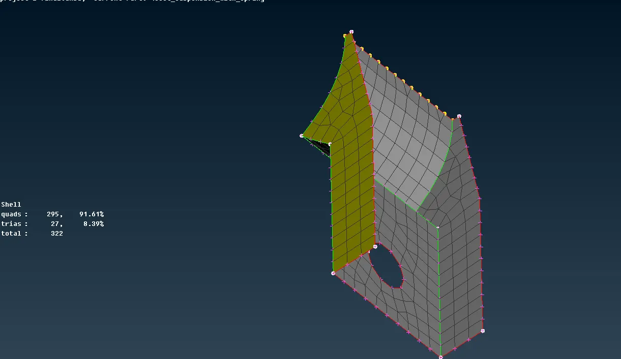
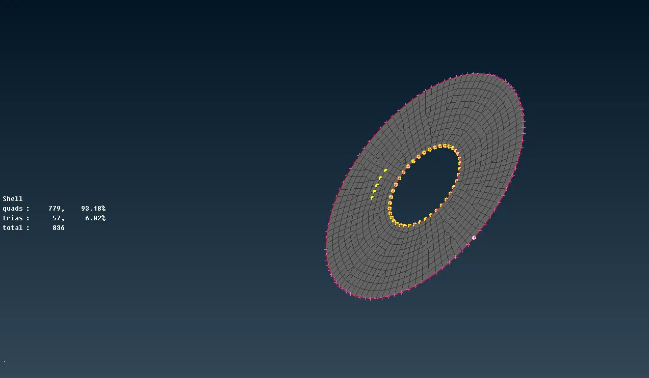
1D Meshing for Spring Like Structure-
In the 1-D element concept, first, we create a curve we assign that curve area so that it can be shown like a spring or bar-like structure.
1- Isolate the feature. ( spring or bar)
2- Use Curves Middle to create a middle curve of the feature.
3- Connect the curve, if any disengagement is there.
4- Switch off the original geometry ( show the curve only ).
5- Measure the length of the curve.
6- Go to the NASTRAN module.
7- ELEMENT - ( CBAR or CBEAM )
8- Select the node of the curve
9- Assing the dia of the curve in PID, and it will calculate the area accordingly.
10- assing the length, and here we can see the curve is converted into a spring or bar as per the curve structure.
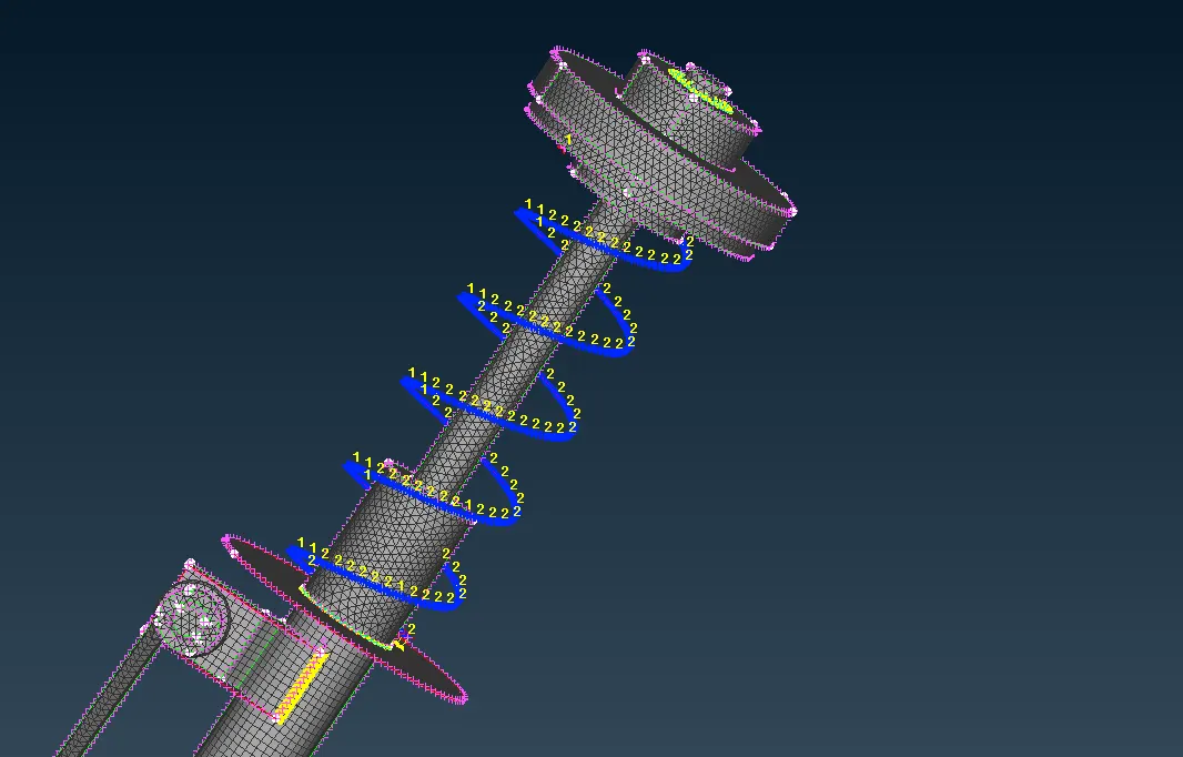
3D Meshing (solid meshing)-
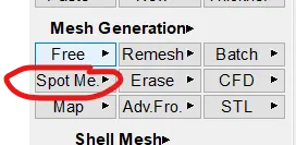
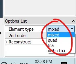
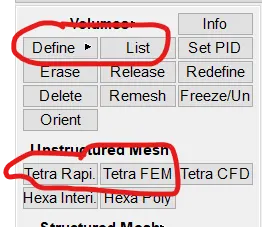
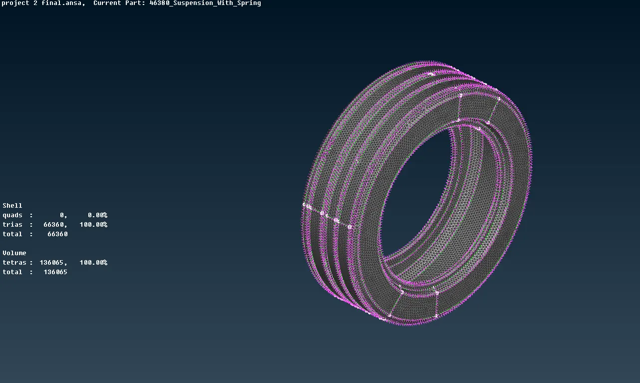
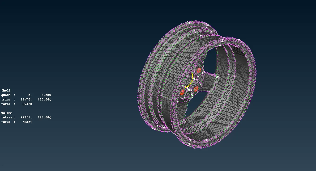
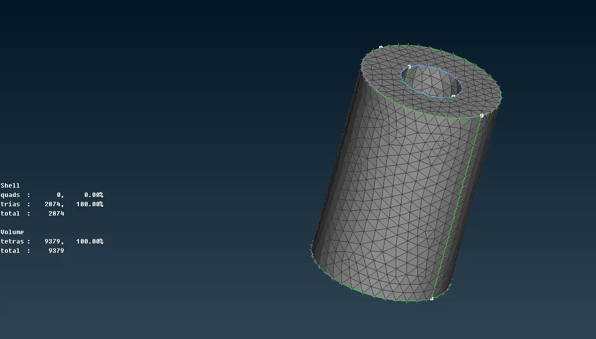
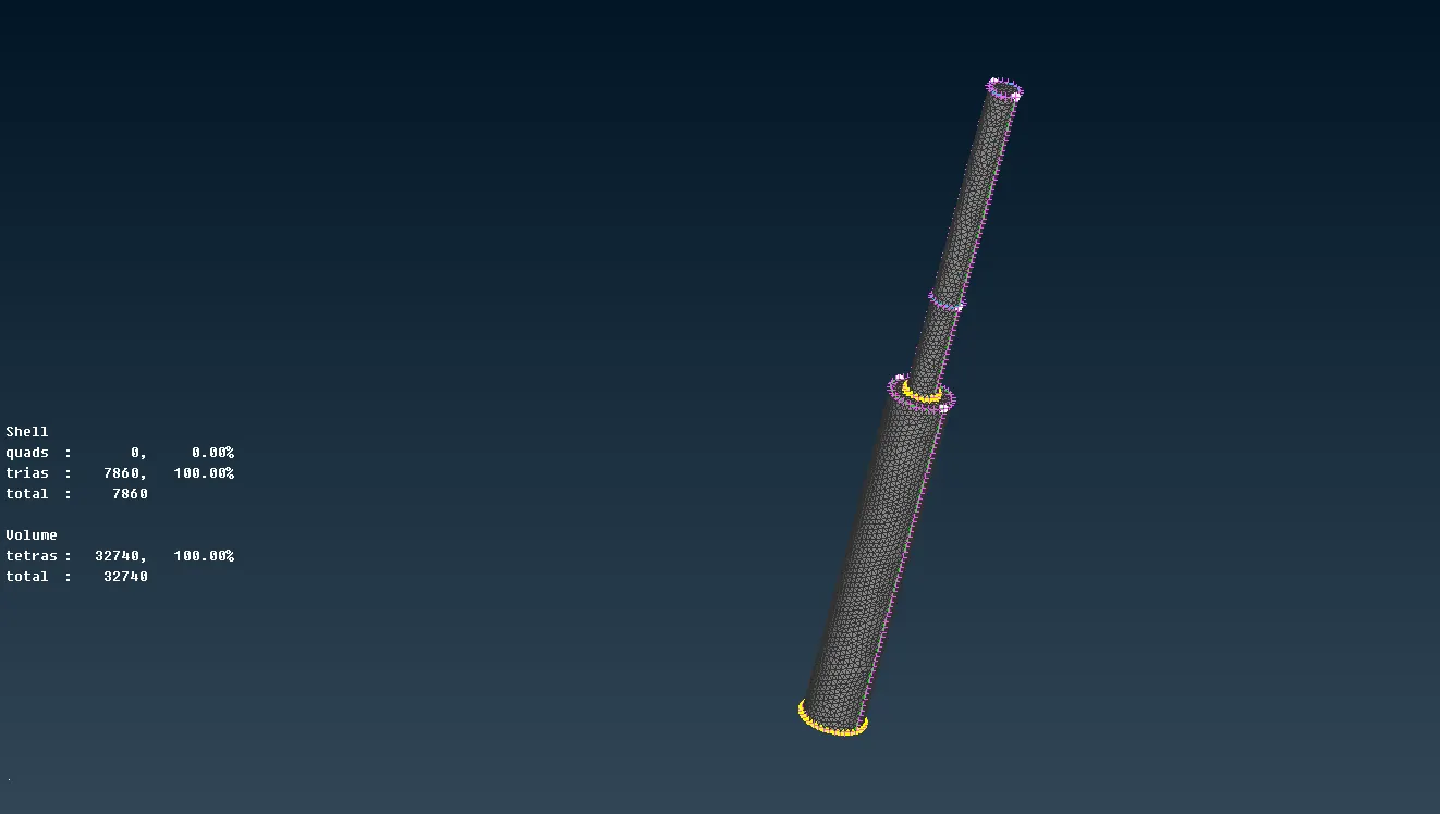
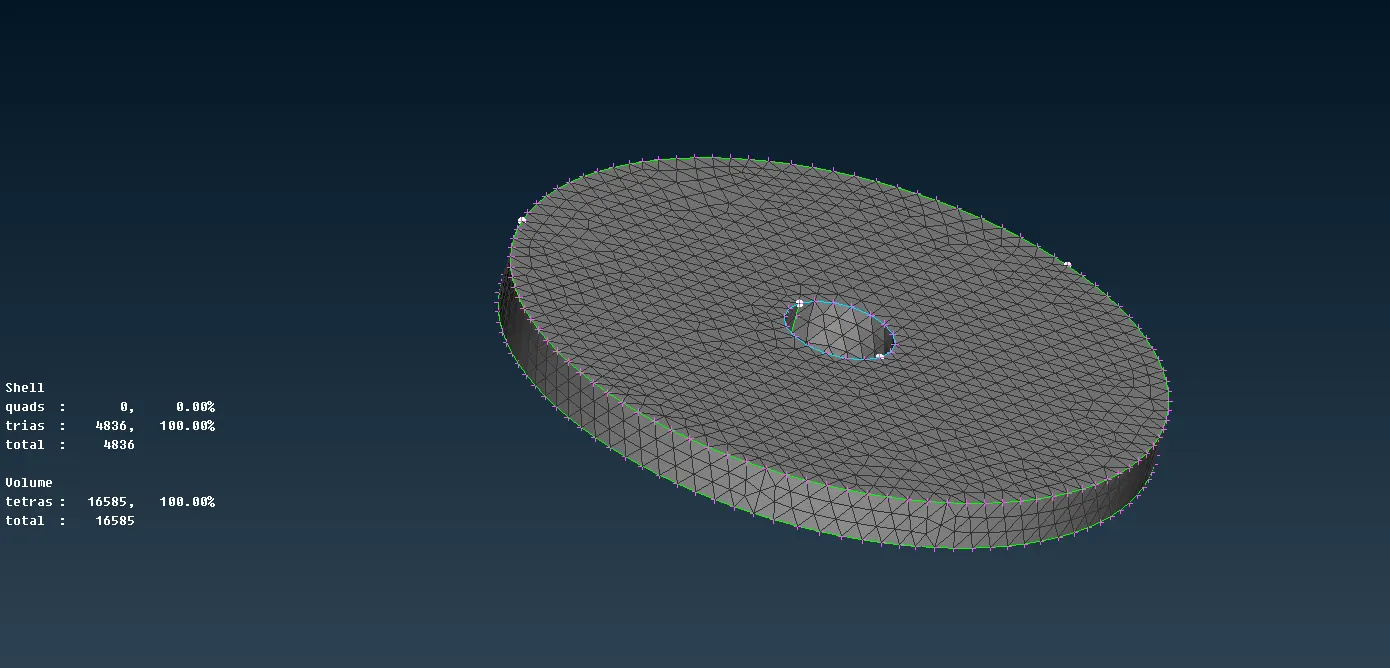
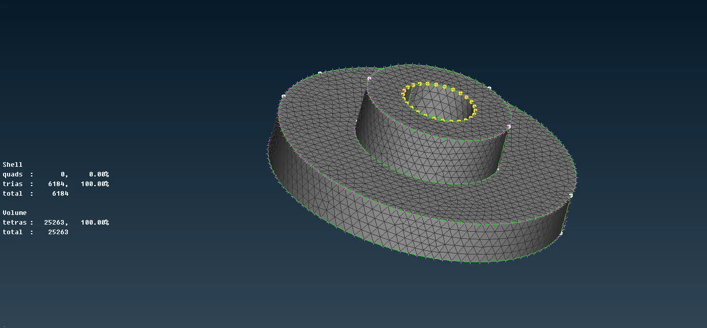
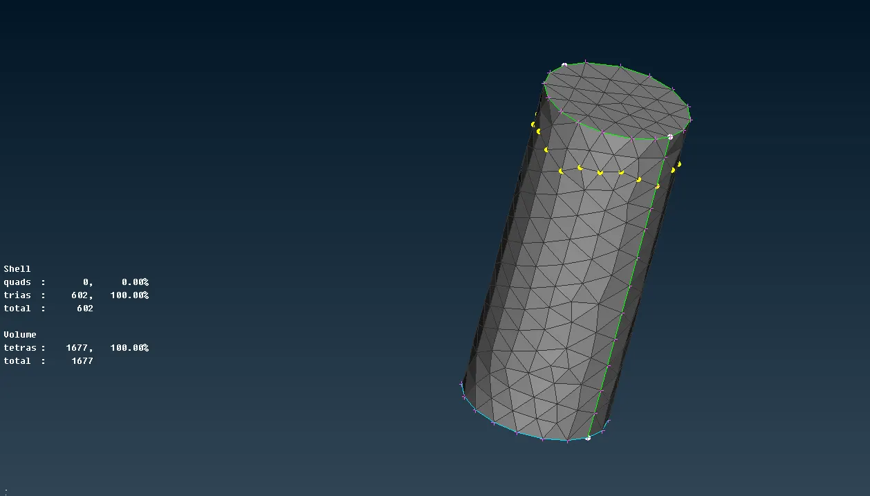
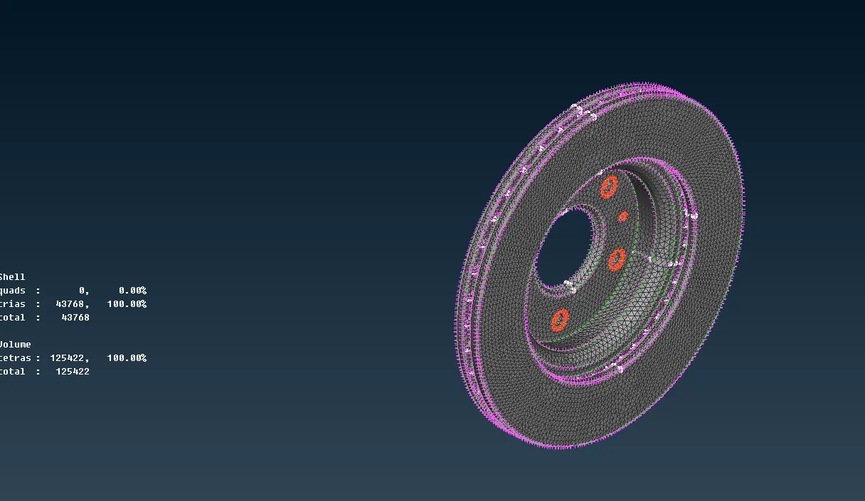
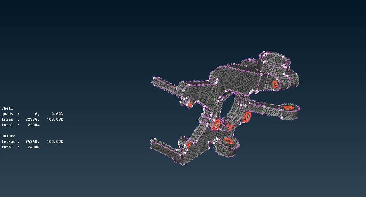
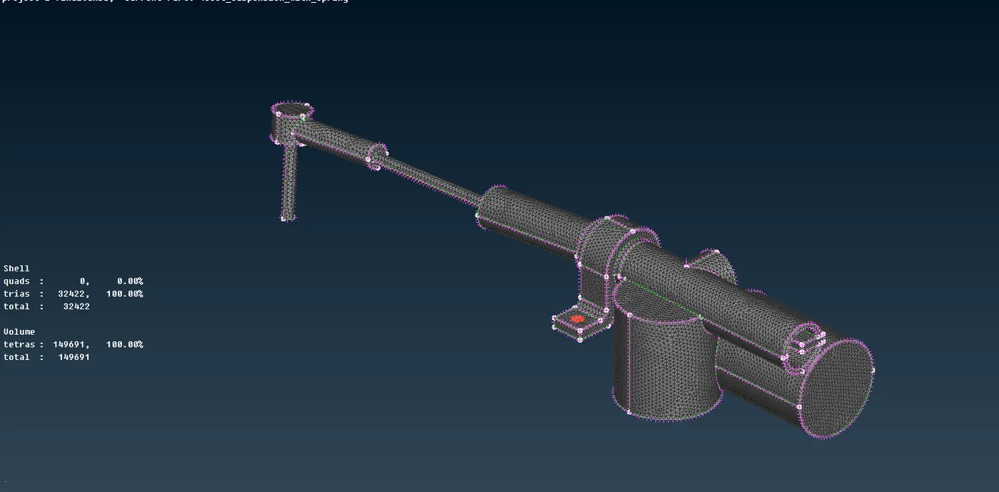
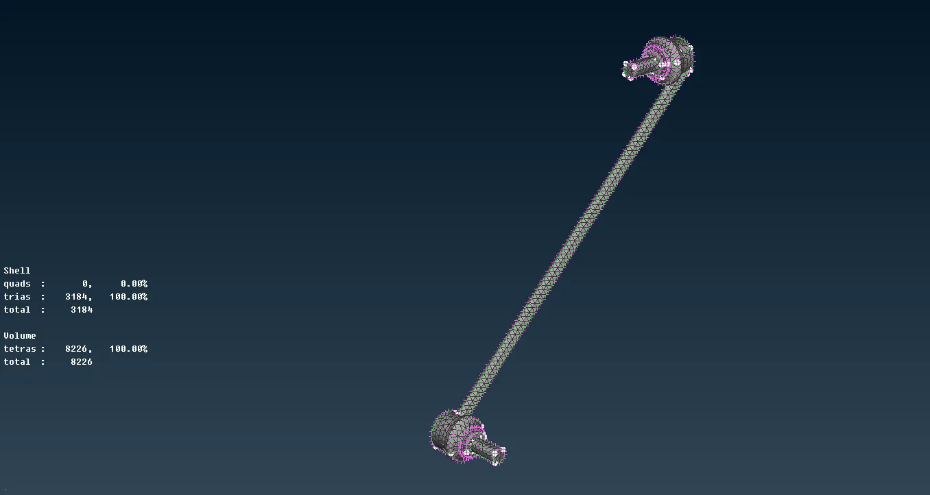
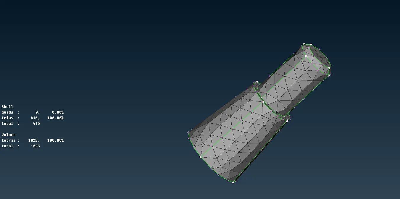
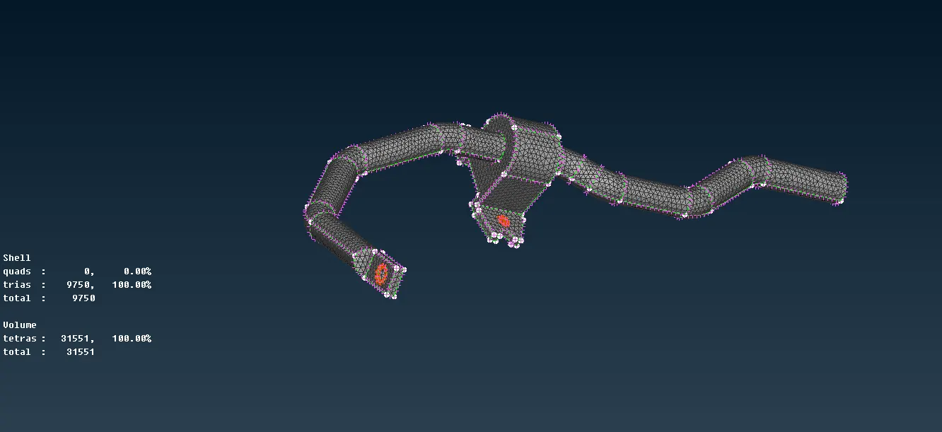
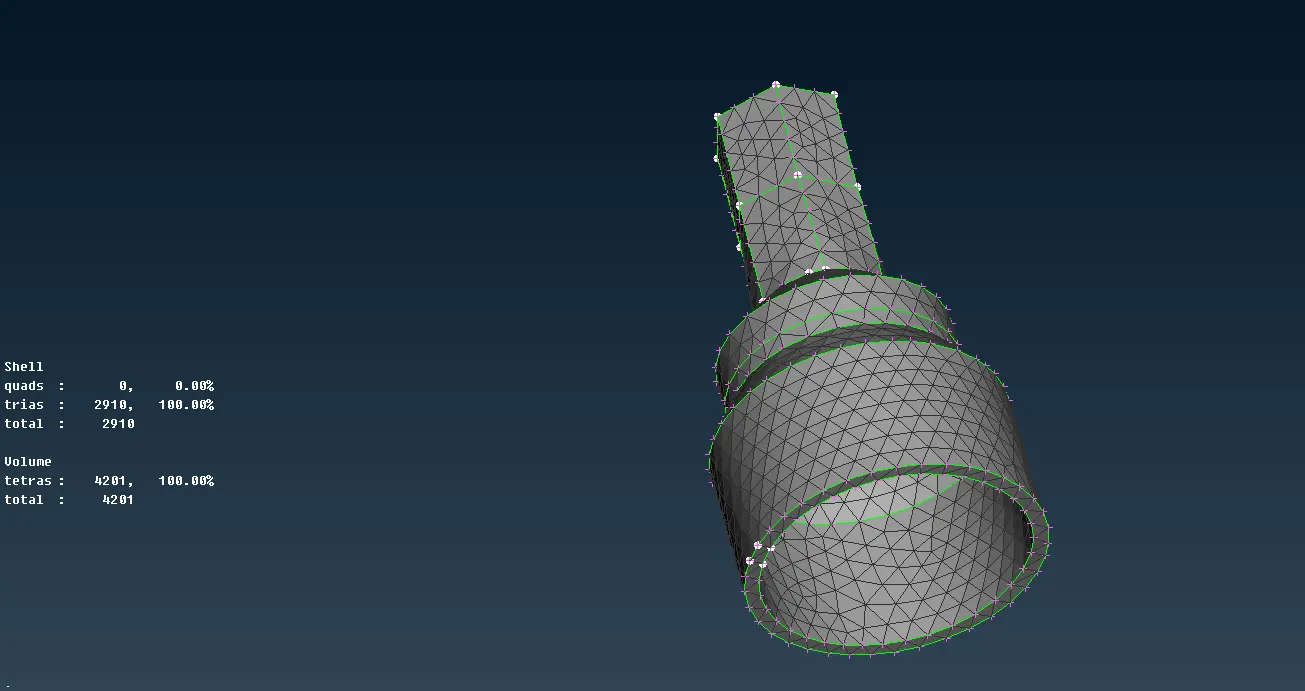
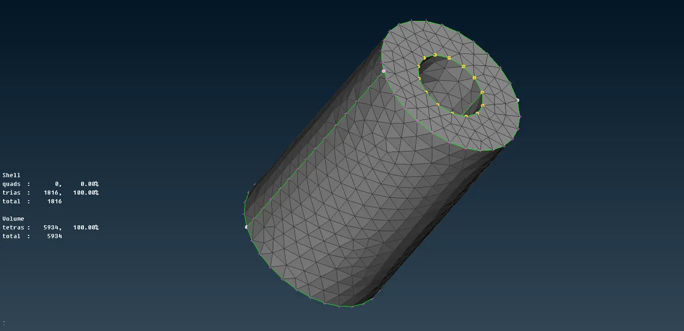
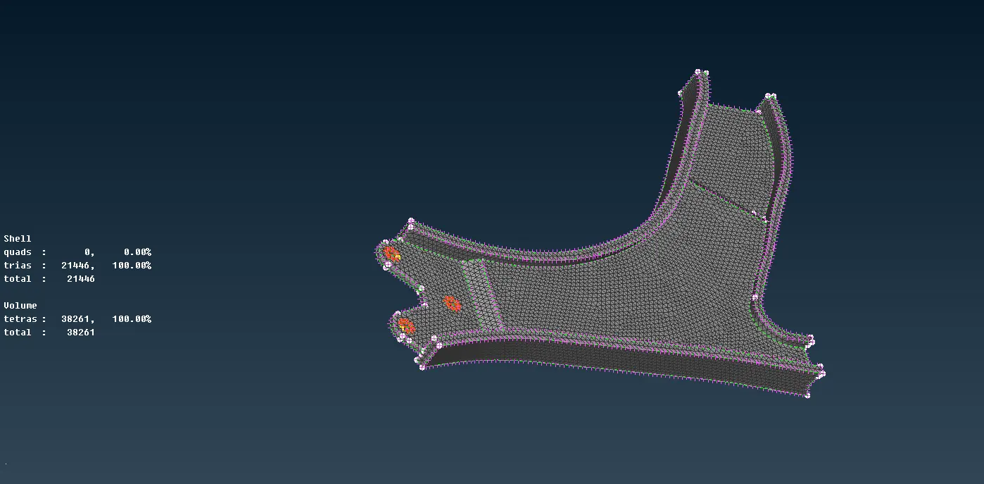
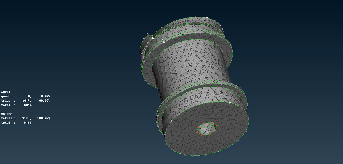
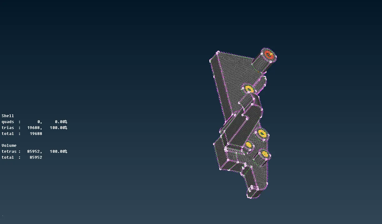
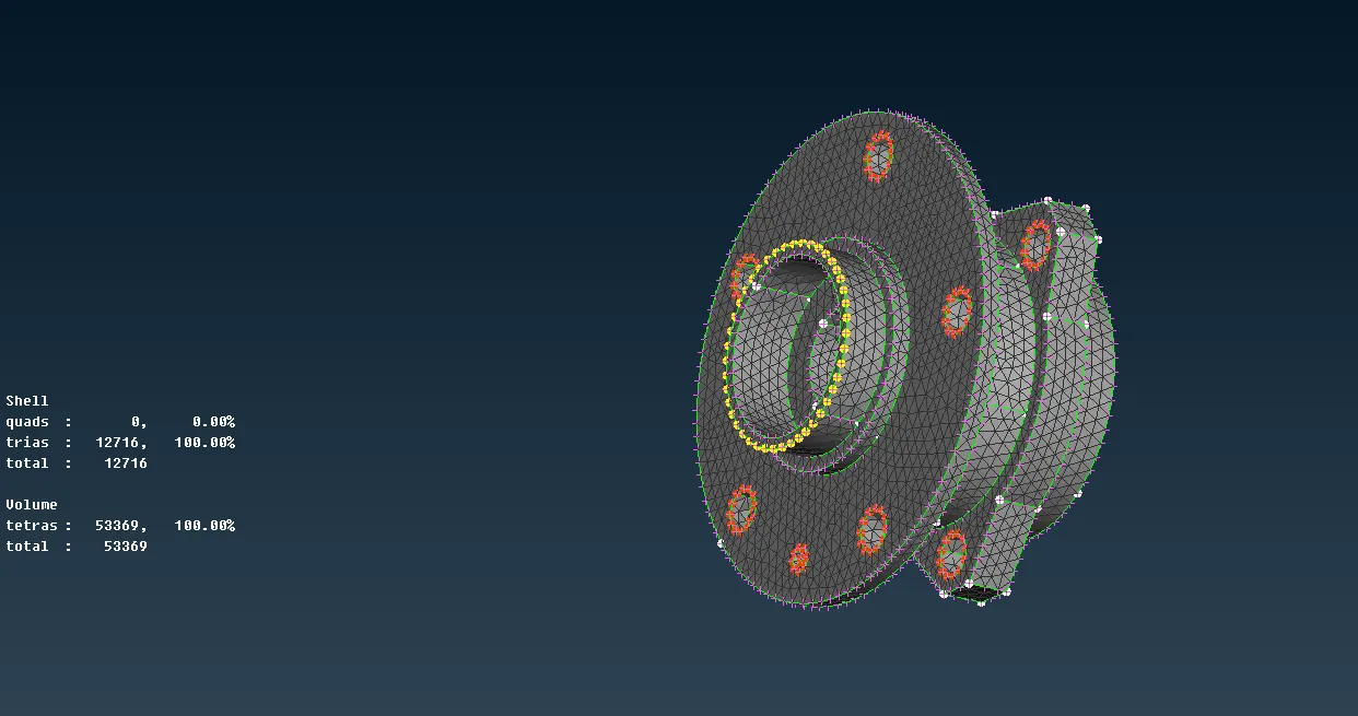
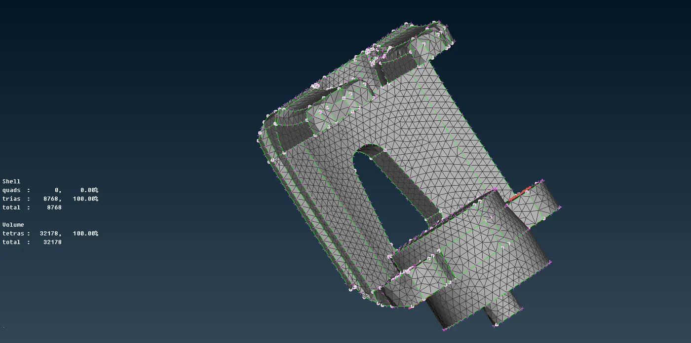
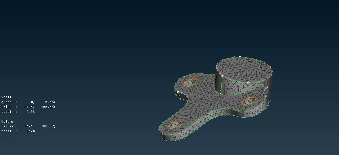
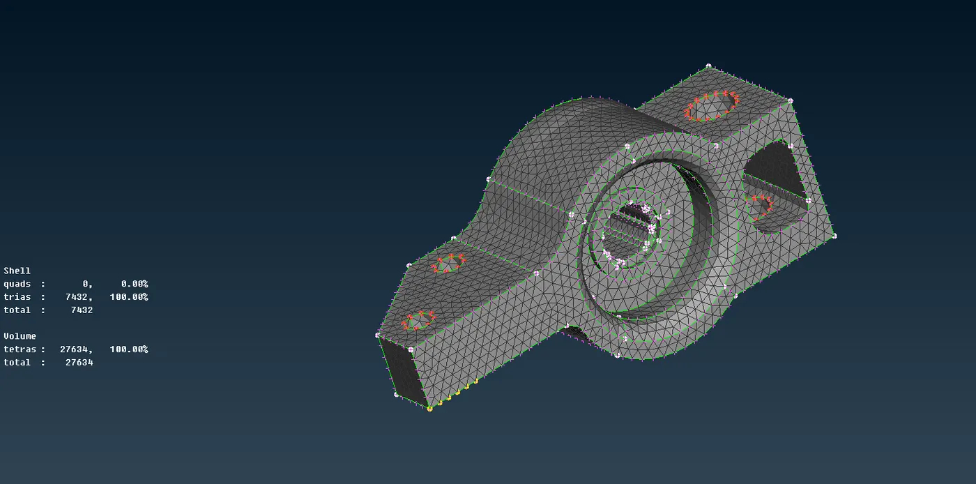
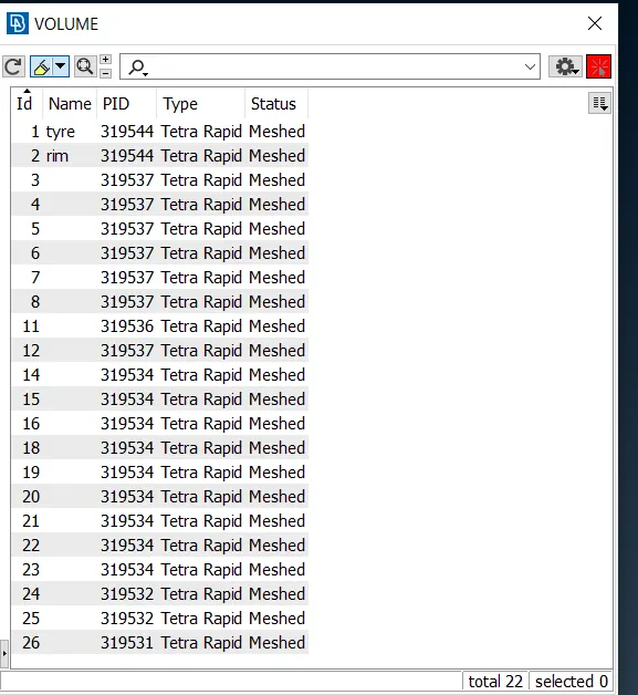
Here we used the spot mesh command to mesh the solid mesh and as per requirement used tria and ortho tria element. After meshing the parts we went for defining the volume of the part and meshing of that volume. For this went for Vmesh command and used define and list command.
1- Here we know that the thickness is already greater than 5 mm we cant use mid surfacing.
2 Also we can see that its a close volume component.
3- So we going for surface meshing and give the volume this mesh.
4- I made some different PIDs for different parts.
5- Went for spot meshing ( Using TRIA and ORTHO TRIA )
6- For the curve surface I used TRIA and for flat surfaces used ORTHO TRIA.
7- Reconstruct the mesh for proper meshing.
8- After Meshinf went for the VMESH module for volume mesh.
9- First used to define command to define the volume.
10- The defend volume we can see in the LIST command.
11- After defining we have to mesh the volume.
12- For meshing the volume there is a command in the VMESH module, TETRA RAPID, and TETRA FEM.
13- WE can use one of them for the meshing of volume.
14- Hereafter applying this command our model is ready.
15- make sure there is no collapse element in volume.
Connections-
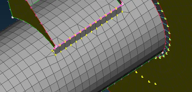
Here we can see that there are many places where so many connections are needed so implemented some bolt and seam weld connection. And for that, some steps have to be followed.
SEAM WELD-
1- Open the model ( FE model ).
2- Mesh the model if we going though mid surfacing.
3- Measure the length of the weld material cons.
3- TOPO module CURVES and the select CONS2CURVE.
4- Select the CONS where u we want to weld.
5- create a curve.
6- Go to convert module.
7- Select the option CURVES.
8- select the point, on confirmation click the seam line option.
9- Here we can see the spot weld created.
10- Now its time for Connection.
11- Go to the connection manager.
12- Select the spot weld, on confirmation new tab, will be open.
13- Select the FE rep type= ( OVERLAP SHELL or Y-JOINT SHELL)
14- OVERLAP SHELL= for parallel parts.
15- Y- JOINT SHELL= for perpendicular parts.
16- Select the ROOT SHELL= ( PRIMARY ROW, OFFSET, DOUBLE ).
14- Search distance according to part 1 and part 2 ( how much distance between them approx )
15- Search distance will vary accordingly.
16- Here in this case we used 20 as search distance.
17- Select the BASE SHEET. ( one with greater thickness ).
18- Select the step length and width.
19- In this case, I used 2 and 3.
18- Select P1 and P2.
19- P1 and P2 according to the base part and second part.
20- The base part should have more thickness than the second part.
21- Now apply and realize.
22- we can see spot weld has performed.
23- GIve PID for the weld.
24- The thickness of the weld part is (t1+t2)/2. , where t1, t2= thickness of P1, and P2.
BOLT CONNECTION-
A- BOLT WITHOUT WASHER-
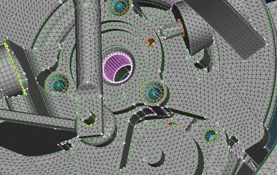
1- Go to the NASTRAN module.
2- Element RBE-2 command.
3- Select the point where the connection is needed.
4- Here we can use ( ENT, FEATURE, LOOP, PID, PATH, NODEL ) module for point selection.
5- On confirmation connection will apply.
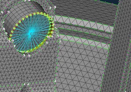
B- BOLT WITH WASHER- ( USE OF ZONE CUT )
1- Creat a zone around the hole for the washer.
2- Use the Mesh module, then SHELLMESH, and select, the perimeter of the hole.
3- We have to give offset here.
4- Offset is nothing but the zone steps around the hole.
5- After giving the offset zone cut will create.
6- Now we can apply the same process as a bolted joint.
a
C- TWO BOLT CONNECTION-
1- For connecting the two colt joints we should select the two nodes of a different bolt.
2- Go to RBE2 and select the TWO NODES option.
3- Select the 2 nodes.
4- And on confirmation connection will apply.
Error Faced-
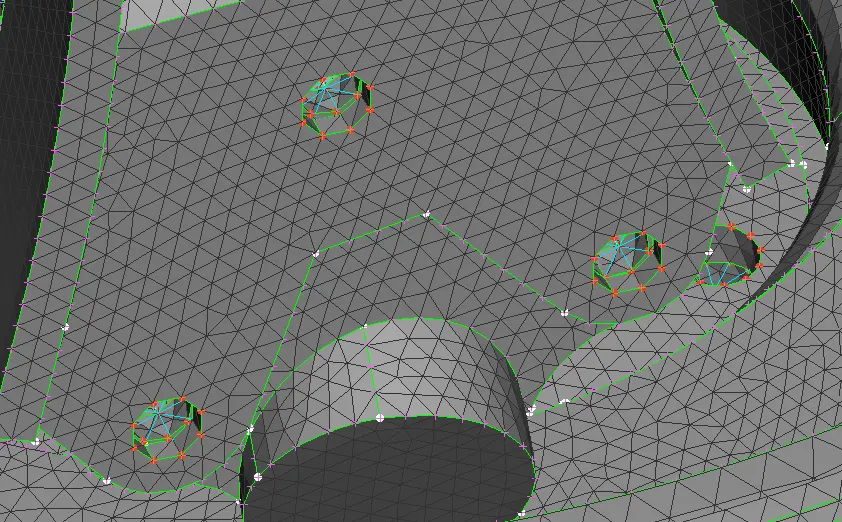
There are so many failing elements for the shell element which can improve by Reconstruct and smooth command. Also, face some Intersection part during the volume meshing which can be fixed by face delete and create a new face. We can fix the Intersection issues by showing only that error then isolate that part lock the part deletes the error or intersected part and create a new part there.
Final Model Result-
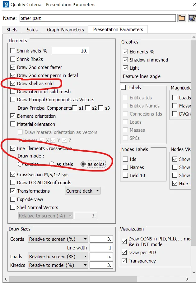
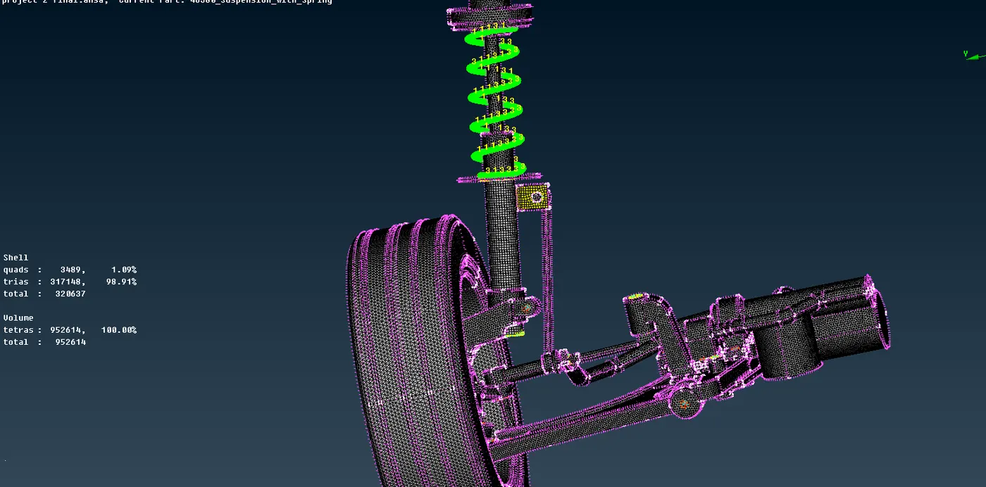
Here we can see the final completed model after completing the volume mesh and assigning the thickness of the model. We can assign the thickness to the model from DRAW SHELL AS SOLID which is located in the quality criteria presentation parameter section. For assing the thickness of the 1D element, there is an option called LINE ELEMENT CROOSECTION which has to be clicked along with AS SOLID from here we can assign the thickness of the 2D and 1D parts.
Conclusion-
Captured all the components of the suspension system model as per requirement and meshed the model with solid (tetra) and shell (quad+tria) as per quality criteria. Successfully implemented the connection RBE2 many nodes and RBE2 two-node as required. There is a total of 952614 tetra elements under the volume meshing (3D) free from any collapse tetra element. Curved are were meshed with tria element and plat are were meshed with ortho tria element for the better mesh. The final model is free from any error, kind, and dip which can be considered for further processing.
Learning Outcome-
1- Geometry cleanup.
2- 1D,2D(SHELL), and 3D(SOLID) meshing.
4- Coneection implementation.
5- Studied the car suspension system.