Sketch a G+1 residential plan according to Vaastu Shastra and Calculation of Loads as per IS code
1. Sketch a G+1 floor residential plan, according to Vaastu Shastra, and list the names of the structural drawings required to be provided to the site for construction. Also, assume the sizes of the structural elements (Column, Beam, Slab, etc.,) and accordingly calculate the individual corresponding loads from the members as per IS code.
Ans: The project's goal is to create a vaastu-compliant G+1 storey dwelling layout and to identify the structural drawings that must be delivered to the building site. Using the size of the structural elements as a starting point, calculate each member's corresponding loads by the IS code columns, beams, slabs, etc. The objective of the project is to illustrate how rooms, spaces, traffic patterns, and other physical aspects relate to one another at a given level of a structure using a scaled picture. The dimensions of the rooms and the lengths of the walls are often drawn between the walls. Notes for buildings that describe finishes, construction techniques, or electrical symbologies may be included on floor plans. The goal of vaastu shastra is to create perfect balance and harmony between nature, people, and their places of residence and workplaces. This will enable everyone to live in peace, prosperity, health, and happiness. Planning a project gives it direction and establishes performance criteria. Knowing about future risks and possibilities is also beneficial.
Using the benefits provided by nature, its elements, and energy fields for improved health, wealth, prosperity, and happiness, vaastu is an ancient Indian science of architecture and building that aids in creating a hospitable environment or a place to live and work. The ancient mystic science of vaastu shastra, which may also be described as a design and construction guide, combines science, art, astronomy, and astrology. We may improve our lives and protect ourselves from problems with the aid of vaastu shastra. A good house must emit the correct sort of energy, such as the sun's influence, the mind's current, the pull of the earth's magnetic field, and other such cosmic forces. A person who lives in a house is subject to a certain energy field. An already-built home cannot be altered in its architecture. The location and orientation of each construction unit must be decided upon by vaastu shastra, and they are as follows:
1. The house's gateway (entrance)
The main entryway serves as both the family's and the energy's entry point.
The main door should be constructed of high-quality wood, ideally teak wood, and be stronger and larger than other doors in the house. Since bright, cherry-colored spaces are connected with excellent energy, the main entryway shouldn't be gloomy. Shoes, undesired items, and garbage bags should be kept from the front entrance. The main entrance should be built such that we may exit and face either north, east, or northeast when we do so. Don't paint the front entrance black or place a statue of an animal close to it.
2. Living room :
Since the family spends most of its time there, the living room should be free of clusters. The living room should face east, north, or northeast. orientation of the living room is northwest. Heavy furniture should be kept facing the living room's west or southwest. Install an electrical device in the southeast corner of the living room. If placing a mirror in this space, the North wall should be chosen.
3. The bedroom
A bedroom facing southwest is a sign of health and wealth. Avoid having your bedroom in the northeast since it might be unhealthy. Avoid the southeast area since couples may argue there. With the head facing west, the bed should be positioned in the southwest corner. Avoid placing a mirror or television near a fountain or splashing water, especially right in front of a bed, as this might lead to arguments and other domestic disturbances. A painting-themed fountain or water feature should be avoided since they might trigger emotional outbursts. using an oasis of calm's scented oil crate. Never go to bed facing north. To maintain excellent health, stay away from overhanging beams. Instead of wrought iron beds, choose solid wood ones.
Positive energy-emitting neutral or earthy colors should be used to paint the walls of the bedroom.
4. Pooja room
A home with spaces for meditation and prayer will promote spiritual development. Your home's east or northeast corner is ideal for spiritual activities like yoga and meditation. When we meditate, facing east will boost our positive energy. The best colors for a meditation room are white, beige, pale yellow, or green. Make a terrified altar and embellish it with candles or incense.
5. Kitchen:
This crucial component of the home needs to be placed in its proper location. Keep a washbasin away from a gas burner. Place the refrigerator in the southwest corner. Never face the kitchen towards the bathroom or share a wall with it.
6. Study room :
Choose a square or rectangular table for your study area. Place the table away from any blank walls or windows. The optimal location for the table is in the northwest, east, or west. Avoid using hanging bookcases wherever possible.
7. Dining area
As the setting sun's rays will destroy any hazardous germs present in the food that has been preserved, the dining hall should be positioned in the west corner. Due to the health benefits of early sunlight, meals can also be done facing east in the home. A perfect square or rectangle should be used for the dining table. The dining room table shouldn't be affixed to the wall. A fridge should face southeast if it is to be placed in the dining room. The member should face the east or north when eating. The main door of the home and the dining room shouldn't be facing each other, and the wash basin should be on the northeast side of the room. The eating area shouldn't be next to the bathroom. Pooja room and restroom doors shouldn't open in front of the eating area.
8. Guest bedroom
As this corner signifies air and is the most unstable in the home, the guest room is ideally located in the northwest. The southwest corner of the room is where the bed should go. The bed should be positioned so that they sleep facing south. The southeast wall of the room should include all of the electrical equipment. The bathroom door shouldn't be directly across from the bed. The bed shouldn't have any beams crossing it.
9. Courtyard
The ancient architecture of the Bahamas is distinctive and based on vaastu shastra. It is the most important and powerful area in your home. In Kerala, the traditional residence is always in the middle of the building. This section needs to be flawless and uncluttered. Negative energy is drawn to where the kitchen, bathroom, pillar, or beam is located.
The drawings illustrate the structure's support system, including how the building is supported, what makes up its structural elements, how strong it is, and how beams, columns, staircases, slabs, and other building components must be delivered to the construction site.
Procedure:
Drawings created in the rough.
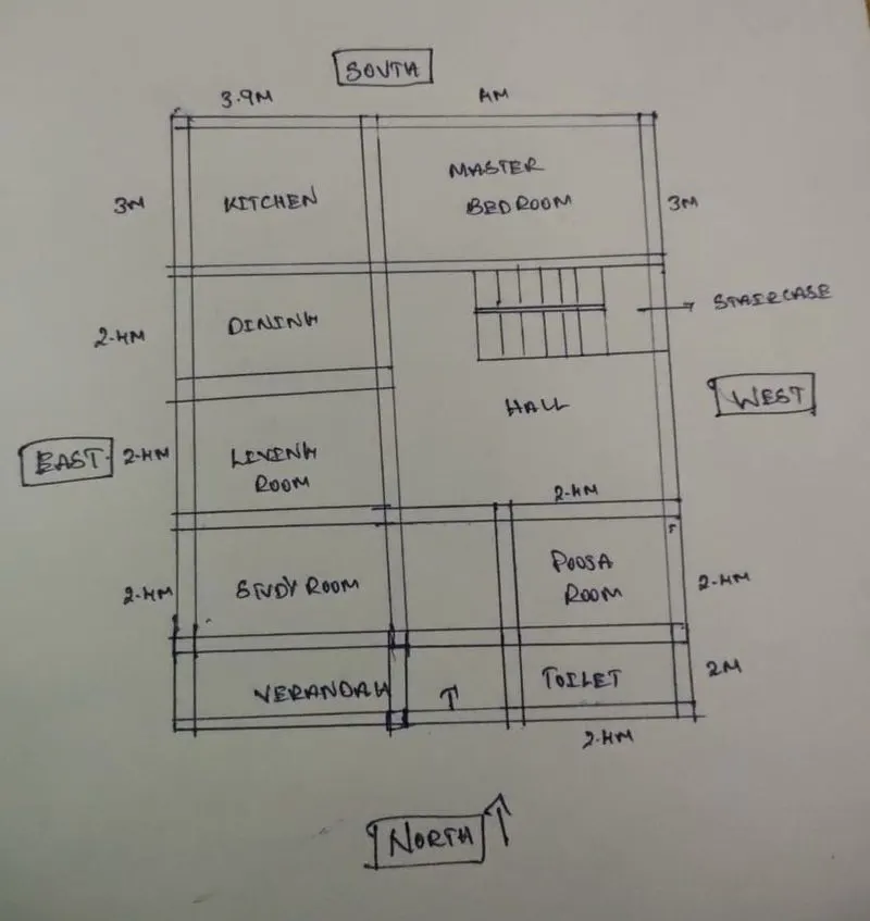
GROUND FLOOR
Bedroom = 4m×3m
Kitchen = 3.9m×3m
pooja room = 2.4m×2.4m
toilet = 2.4m×2m
living room/study room/dining room = 2.4m×3.9m

FIRST FLOOR ( In the place of the verandah, the balcony is placed)
Dimensions of first-floor plan:
Bedroom = 4m×3m
Kitchen = 3.9m×3m
pooja room = 2.4m×2.4m
toilet = 2.4m×2m
living room/study room/dining room = 2.4m×3.9m
Other dimensions
The thickness of the external/internal wall = 0.23m
thickness of slab = 0.25m
dimensions of column = 0.3m×0.3m
dimensions of beam = 0.3m×0.45m
height of the wall ground floor = 4m
height of the wall 1st floor = 3.5m
Calculations of loads:
Dead load calculations:
A) The dead load of columns
dimension of column = 0.3×0.3 m2
height of column = (slab thickness × 2) + height of wall from ground floor + height of wall from first floor
= (0.25×2) + 4 +3.5 = 8m
total volume of 1 column = 0.3×0.3×8 = 0.72 m3
from, IS875 Part 1
Dead load of 1 column = volume * unit weight of Rcc = 0.72×25 = 18KN
B) Dead load of beams
dimension of beams = 0.3×0.45 m2
the total volume of beam per meter length = 0.3×0.45×1 = 0.135 m3
unit weight of Rcc = 25KN/m3 from, IS875 Part 1.
the dead load of beam per unit length of beam = 0.135×25 = 3.375KN
C) a Dead load of slabs
the slab is always designed for a span of 1m3
hence assume the size of the slab is 1m×1m
unit weight of Rcc = 25KN/m3 from, IS875 Part 1.
the total volume of span per square meter area = 0.25×1×1
the dead load of span per square meter area = 0.25×25 = 6.25 KN
D) a Dead load of walls
thickness external/internal = 0.23m
unit weight of brick masonry = 20 KN/m3 (from IS875: part 1)
height of ground floor wall = 4m
dead load for ground floor wall per unit meter length = volume of wall per meter length×unit weight of brick masonry = 4×0.23×1×20 = 18.4 KN
height of first floor wall = 3.5m
dead load for first floor wall per unit meter length = volume of wall per meter length×unit weight of brick masonry = 5×0.23×1×20 = 16.1 KN
Total weight of both ground floor per meter length & first floor length = 18.4 +16.1 = 34.5 KN
2) Live load calculations:
As per IS875 Part 2, for residential buildings live load has taken as,
living / dining = 2kn/m2
kitchen / bedroom / toilet = 2kn/m2
staircase = 3kn/m2
3) Wind load calculations:
If the height of the building is more than 10m then the building needs to be designed for wind load.
but, in this case, the building of height is 8m thus, wind load need not be considered.
List of important types of construction drawings used in any project
- Site Layout Plan
- Floor Plan
- Sectional Drawing
- Structural Drawings
- Working Drawings
- Foundation Plan
- Column Layout Drawings
- Plinth Beam Layout Drawings
- Flooring Details Drawings
- Doors & Windows Frame Details
- Sill and Lintel Level Drawings
- Column, Beam, and Slab Reinforcement Details
- Staircase Layout and Reinforcement Details
- Plumbing Layout Drawings
- Electrical Layout Drawings
- Finishing Drawing
1. The site map
A site plan is a sketch or layout of the planned building construction site that has been scaled up. It covers the size and shape of every single existing structure as well as all of its details. A site plan, commonly referred to as a site layout plan, displays how a site's various components are arranged. An architect or planner might use a site plan to gain an overview of the characteristics already present on the property, design appropriately, and decide whether to demolish them if necessary.
The site plan must include the following information:
- Site perimeter and specifics of any nearby homes or constructions.
- The building's position or placement in its surroundings.
- The key components of the landscape, as well as location information for tree protection orders.
- Location or capacity of the parking lot, traffic patterns, and signs.
- Paved surfaces, ramps, walks, existing roadways, etc.
2. Floor Plan
One of the most significant categories of building drawings is the floor plan. The layout of the space is depicted in two dimensions on the floor plan, along with each component's location and size. The location and arrangement of the drawing room, living room, kitchen, bedroom, staircase, bathroom, W.C., etc. were all included. For a site engineer, the floor layout is essential. The floor layout may also show any fixtures or items that are stored in the room. However, it is not a need for a floor layout. It simply provides a broad overview of how the space will look after the furniture is in place.
3. Sectional Drawing
The line elevation of the building is the same in a section drawing, which is cut in a vertical plane inside the building plan. Furthermore, when cut vertically inside the building, it depicts the building's intricacies. Similarly to that, sectional drawings are crucial to obtain information about internal components. Typically, the floor plan simply displays two dimensions—lengths and widths—plus the component's height. Consequently, it can be seen in the building's sectional design.
4. Structural Drawings
A structural drawing is a design or collection of drawings outlining the construction of a building or other structure. Typically, qualified professional structural engineers with a background in architecture prepare it. The major focus of structural drawing is on a structure's load-bearing components. In addition to outlining the fundamental requirements for connections, they also define the size and materials that will be employed. Architectural details like surface treatments, partition walls, or mechanical systems are never provided in the building sketch. For the building authority to assess, the structural drawings deal specifically with the design of the building's structure. The contract documents that contractors use to specify, fabricate, and install the structure's components are also included in structural drawings.
5. Working Drawings
A working drawing is necessary to carry out building activities. These serve as the site engineers' primary instructions for erecting the structure as intended. On building sites, many working drawings are utilized, including floor plans with measurements, foundation plans, flooring specifications, etc.
6. A foundation design plan
The most significant category of construction drawings is the layout design for the foundation. It is a blueprint that contains information on the building's foundation. The foundation plan contains the following information, for example: types of foundations that can be built, dimensions, and form of the foundation, dimensions, and separation from one another, building and component symmetry, and information on excavation and PCC.
7. A plan or drawings for the column layout
The size, shape, position, and dimension information for columns is included in the column layout design. Without a column layout plan, the initial framework of any building cannot be built. It is a crucial design or blueprint. The column containing their identifying numbers, such as C1 or C2, is displayed in this design. The site engineers can find and build columns on the property with the use of this layout plan.
8. Drawings for Plinth Beam Layout
It is a sort of construction design where the plinth beam layout plan or drawing describes the position, layout, size, and reinforcing features of the plinth beam. It is a crucial design for planning the formwork configuration for the plinth beam.
9. Floor Plan Drawings
When a building is being constructed, the flooring plan outlines the dimensions, material kinds, and intended flooring types. It also displays information about the flooring's subfloor.
10. Frame details for the doors and windows
The location of the door and windows in the wall is shown on the plan for these modes of mobility. While fixing the windows, it displays the position, window height, and frame position.
11. Drawings with Sill and Lintel Levels
These drawings provide a sectional view of a wall with sill and lintel levels. It contains information on the lintel's dimensions (length, breadth, and thickness) on the wall. It is a crucial kind of drawing that is utilized in building construction.
12. Details of Column, Beam, and Slab Reinforcement
When building columns, beams, and slabs, this drawing is crucial and significant. Details of the formwork, cover, and reinforcement are shown in this drawing. It facilitates the site engineer's interpretation of the steel reinforcement's diameter and spacing while building columns, beams, and foundations. Additionally, it displays the distance from the center of the column to the center of the beam, which aids in the accurate placement of structural elements.
13. Staircase Layout and Reinforcement Details
It displays the staircase's arrangement in detail using typical proportions. It contains information on the size of the landing, the number of risers and treads, the length and breadth of the stairs, etc. It is a crucial sketch while building stairs. The staircase design and section display the specific reinforcement, stair flight angle, and cover that will be applied.
14. Drawings of plumbing layout
This category of construction drawings is significant. Plumbing work has to do with the home's water supply system. It covers the schematic design of various systems for supplying water to the house's various rooms. The plumbing design specifies the location of the outlet point, the size of the pile, the material of the pile, and its position.
15. Electrical Layout Drawings
It is a diagram that shows the precise placement of various electrical fixtures, such as switchboards, light points, fan points, and ceiling points. This layout plan may be examined by an electrical engineer who can then determine how much material is needed to electrify the structure. Lighting layout, switchgear layout, generator and other equipment layouts, Earthing layout, lightning protection system layout, cable layout, conduit layout, cable tray layout, and area classification layout in hazardous areas are examples of several types of electrical layout drawings.
16. Finishing Drawings
The final details of each component, such as the flooring pattern, painting color, false ceiling form, plastering texture, and elevation design, are shown in the finishing drawings.