Sketch a G+1 residential plan according to Vaastu Shastra and Calculation of Loads as per IS code
AIM-
- To prepare a G+1 floor residential plan, according to Vaastu Shastra
- To list down the names of the structural drawings required to be provided to the site for construction.
- To calculate the individual corresponding loads from the members as per IS code and assume the sizes of the structural elements for it.
INTRODUCTION-
1)Vaastu Shastra-
Vastu Shastra is an ancient Indian science of architecture which acts as a guideline to design home in a way that enhances positive energy. It is an ancient science which propounds theories based on direction, architecture, astronomy or even astrology.
Basic principles of Vastu Shastra:
1)Shape- rooms should be rectangle or square.
2)Room basics- rooms should be airy, well lit, bright and clean.
3)Home center- centre of the house should be an empty space.
4)Stairs and furniture- it should be in south-west direction.
5)Water features- Plants and water features should not be kept in the bedroom.
6)Dining table- dining space should be near the kitchen and not near the main door.
7)Mirror placement- mirrors in the bedroom need to be placed in such a way that the bed cannot be seen.
Auspicious directions as per Vastu Shastra:
1)Kitchen- south-east is the best and north-east should be avoided.
2)Toilet- north-west is the best and north-east should be avoided.
3)Staircase- north-east to be avoided and south-west is the best.
4)Underground tanks- north-east is the best and south-west to be avoided.
5)Over head tanks- west is the best.
6)Living room- north-west is the best.
7)Guest room- north-west is the best.
8)Master bedroom- south-west is the best.
2)Sequence of construction-
The steps followed before the construction are as follows :
1) Acquire & survey land
2) Seek technical consultant
3) Design process
4) Estimation of budget
5) Building permits ( soil testing report, plan and elevation approval, structural certificate from government, architect certificate)
6) Approach contractor
Procedure followed in construction :
1.Clearing the site – obstruction at site like big rocks are removed, garbage is cleared and the site is cleared for unwanted grass and levelled as per the fixed ground levels provided in the drawing. Site perimeter fence needs to be constructed during this period. Temporary facilities like labour quarters, material storage room etc should be constructed prior to start of the work.
2.Site layout and stacking – in simple words it means marking the ground as per approved plans. Site layout and staking involves the setting of reference points in the form of construction grid lines and marking off the gate level. Construction grids for small projects are laid using batter board and strings.
3.Excavation- after gridding we go for excavation. The depth of excavation depends on the recommendations of the soil investigation report. For safety the minimum excavation level for the footing to rest should stick to one metre below the finished ground level . Proper precautions should be taken to keep the existing structures undisturbed. For this shoring support can be provided to the existing structures.
4.Compaction and laying of PCC – compaction is done after excavation . A layer of crushed gravel is placed. After that anti-termite treatment is given. After this PCC( 1:2:4) is laid .
5.Foundation rebar and column starter bars - Rebar works for foundation are done once PCC is laid. Starter bars for the columns needs to be installed before the pouring of concrete.
6.Foundation concreting and column rebar installation – After the rebar works, concreting for foundation is done. Installation of column reinforcement on the installed column starter bars should be continued. Concrete cover needs to be provided before the formwork is done.
7.Column concreting and bitumen paint applications- once concreting of stub columns are completed ,time is given to allow it to dry completely. After the concrete dries, two coats of bitumen paint for both footing and stub columns are applied. Bitumen paint helps in absorbing moisture due to the soil to prevent seepage into the substructure concrete.
8.Setting up perimeter blocks- solid blocks are installed along the edge of the project. This establishes a boundary between the inside and outside edges of the project. It also helps to identify the significant level difference in floor finish levels of inside to outside pavement or ground level.
9.Backfilling and compaction - backfilling and compaction takes place when the substructure work is completed. Backfilling and compaction should be done to make sure that the required degree of compaction is done at the bottom.
10.Reinforcement for tie beam, grade slab and concreting – as per the drawing, reinforcement bars for tie beam are installed . Formwork with standard concrete cover is to be included in this stage. Reinforcement mesh for grade slab is installed and the concrete work is followed.
11.Rebar works and column concreting- these works are done when the concreting of the substructure component is completed. The next work is the rebar works, shuttering, formwork and concreting for the column.
12.Beam and slab works- this takes place after the completion of ground floor columns. Shuttering and form work for beams and slabs should be properly checked prior to concrete pouring. The same process of column and beams is followed for all subsequent floors till the structural core and shell of the structure is completed. Architectural finishing works are done then.
13.Wall construction – walls are constructed using bricks, blocks ,precast concrete etc. 1:6 mortar is used. The base of wall is constructed first using concrete or stone masonry. Necessary openings for windows and doors needs to be provided.
14.Construction of lintels - a lintel is a beam that is usually placed above windows and doors. Reinforced cement concrete beams are laid at top of the openings to protect the loads directly coming to the door and window frame. The lintel's main job is to support the load from the structure above it. Both doors and windows are not constructed to structurally withstand massive loads by themselves.
15.Plastering work – plastering is done after the brick work is done. Mortar for plastering work is normally 1:4 or 1:3 . Thickness should not be more than 0.75 inches.
16.Fixing of doors and windows – wooden frames are fixed for doors and windows during masonry work. Panels are fixed with hinges after plastering is done.
17.Fixing of electrical and plumbing works – plumbing and electrical works are carried out before the finishing works are done.
18.Tile laying – Granite and marble tiles together with epoxy are used for flooring works. Wall tiles are fixed first and then the floor tiles are fixed.
19.Painting- it consists of different sequences:
- 1 coat of primer and 2 coats of water based paint
- 2 coats of painting after doing 2 coats of putty for smooth finish
20.Miscellaneous works- it includes false ceiling, landscaping works, waterproofing at terrace etc.
3)Drawings-
1)Centre line drawing-
- Drawing should show all column positions.
- Drawing should contain all the grid positions same as that provided in the architectural drawing.
- Dimensions provided for the column should be respect to the grid.
- Structural notes should be provided in the drawing.
- Columns should be numbered.
- Grid to grid dimensions should be provided in the outsides(outside of buildings).
2)Footing and column layout-
- Size of footings should be shown.
- Dimension of footings from the grid positions should be shown.
- Outer line of footing (white dotted line) shows PCC under the footing. This should not be missed.
- Red line is the footing line.
- Lift pit should also be shown.
- Grid to grid dimensions should be provided.
- Footing numbers should be provided.
- Structural notes should be provided.
- Provide standard footing details if there is space available or else provide it in the next drawing.
3)Column schedule with reinforcements-
- It is mandatory to provide the typical reinforcement drawing of footing. It can be provided in the previous drawing also if there is space. Information about the ties should also be stated.
- Column reinforcement details should be shown stating number of rods, reinforcement diameter, stirrup diameter and distance between the stirrups.
- Column categorization should be shown.
- Footing schedule should be shown stating footing categorization.
4)Liftpit drawing-
- Liftpit plan drawing should be shown.
- Liftpit plan with top slab drawing should be shown. Reinforcement details of the roof slab should be clearly visible.
- Reinforcement drawing of RCC wall should be shown. Both plan and section drawing should be mentioned.
- PCC, sand filling, RCC wall and water proofing layer should be visible in the section drawing.
- For a lift pit,in the lift drawing, there should be beam at roof slab level to connect the roof slab in that area and a lintel beam where door is provided.
5)Plinth beam layout-
- Columns connected by beam in the plinth level should be shown.
- Size of all plinth beams must be shown ,example: 9''x15'' where 9 inches is width of the beam and 15 inches is depth of the beam.
- Grid to grid dimensions should be provided.
- Reinforcement drawings of all plinth beams should be shown.
- Plinth beam connecting two beams and not columns must also be shown and named.
- Plinth beams should be properly numbered like PB1, PB2, PB3 etc.
6)Slab and beam detail drawing-
a)Layout of slab over stilt floor-
- Same beam pattern should be shown as in previous drawing.
- Sunken slabs should be shown where there are toilets. Depth up to which it is sunk from normal slab level should be clearly shown.
- Beam details should be shown.
- Reinforcement details of all beams in the floor should be shown.
- Also show lift wall.
b)RC details of slab over stilt floor-
- It is not necessary to provide grid dimensions.
- Reinforcement details of slab should be shown.
c)Layout of slab over first floor- similar to (a)
d)RC details of slab over first floor-similar to (b)
e)Layout of slab over second floor-
- Beams connecting the columns should be neatly shown.
- Lift wall should be shown.
- Sunken slabs should be shown.
- Reinforcement details of all sections of beams should be shown.
- While designing the staircase we should provide beams at the heights where we are providing the landings. We should provide mid landing beams where we are planning to provide landing for staircase.
- Mark all the dimensions.
f)RC details of slab over second floor-
- Reinforcement details of slab should be shown. Information about main bars and distribution bars should be given.
- Open space for lift is hatched showing that there is no need of slab on it.
- Grid to grid dimensions will not be shown.
g)Layout of roof slab and RC details of roof slab-
- It is mandatory to show floating columns. Reinforcement details of floating column and its size details should be shown.
- Reinforcement details of beams and slabs should be shown.
- Top roof floor beams should be clearly shown.
- Grid dimensions needs to be provided.
7)Headroom and lift roof drawing-
- "Note- lift hook is to be fixed as per vendor drawing". This should be written on the drawing if required.
- Naming of all the beams should be done.
- Reinforcement details of head room beams and lift beams should be shown.
- Mention grid to grid dimensions.
- Reinforcement details of headroom and lift roof should be shown.
4)Types of loads-
A)Dead load- these are permanent loads acting on a structure throughout their life span. These are stationary loads that occur mainly due to the self-weight of the structure. Weight of reinforcement bars and concrete in structural elements are considered as dead loads on a structure. Dead loads are calculated by multiplying the quantity of each material with the unit weight of that specific material.
B)Live load- live loads are real-time loads. These are also called as imposed loads or sudden loads. Live loads in a structure changes with respect to time. Live load includes the weight of the furniture, people occupancy etc. Loading details for design needs to be considered as per Indian code IS875: part-2.
C)Wind load- theses horizontal loads are caused by the wind on the structure. Wind loads act horizontally towards walls and roof surface. We use IS 875 (part3 )- 2015 to calculate the wind load. If the height of the building is more than 10m, then the building needs to be designed for wind load.
Wind load calculation procedure-
1)Find the basic wind speed (Vb) using figure1 of the code. Basic wind speed for some important cities and towns is given in Annex A.
2)Calculate design wind speed using
Vz = Vb x k1 x k2 x k3 x k4
where
Vz = design wind speed at height z in m/s
k1 = probablity factor (risk coefficient) (see clause 6.3.1 ,table 1)
k2 = terrain roughness and height factor (see 6.3.2.2, table 2)
k3 = topography factor (see 6.3.3)
k4 = importance factor for the cyclonic region (see 6.3.4)
3)Calculate wind pressure using equation:
Pz = 0.6Vz^2 where
Pz = wind pressure at height z in N/m^2
4)Calculate design wind pressure (Pd) using equation:
Pd = Kd.Ka.Kc.Pz
where
Kd = wind directionality factor (see 7.2.1)
Ka = area averaging factor (see 7.2.2 and table 4)
Kc = combination factor (see 7.3.3.13)
However, the value of Pd shall not be taken less than 0.70Pz
5)Calculate wind load on individual members using equation:
F = (Cpe - Cpi) .A .Pd
where
F = wind load acting in a direction normal to the individual structural element or cladding unit
Cpe = external pressure coefficient (see Table 7)
Cpi = internal pressure coefficient (see 7.3.2.1 and 7.3.2.2)
A = surface area of structural element or cladding unit
Positive wind load indicates the force acting towards the structural element and negative away from it.
PROCEDURE-
Ground floor residential plan-
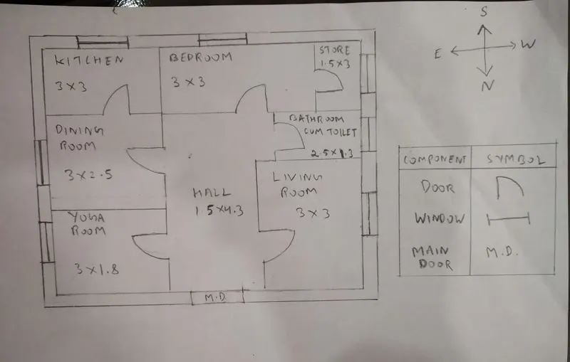
First floor residential plan-
The structural drawings required to be provided to the site for construction are as under:
- Centre line drawing
- Footing and column layout with reinforcement details
- Column schedule with reinforcement details
- Plinth beam layout with reinforcement details
- First floor beam layout with reinforcement details
- First floor slab with reinforcement details
- Lift pit,lift roof and headroom with reinforcement details
LOAD CALCULATIONS-
Assumptions-
1)All columns have cross-section 300mm x 300mm and height 4.5m.
2)All beams have cross-section 300mm x 450mm.
3)Slab thickness is 125mm.
4)The height of the wall is 4.5m and thickness of the wall = 230mm.
All beams,columns and slabs are made of RCC and the wall is made of bricks.
Note- unit weight of RCC and brick masonry are 25kN/m^3 and 20kN/m^3 respectively.
DEAD LOAD-
Calculation of self weight of the column-
Volume of the column = 0.3*0.3*4.5 = 0.405m^3
Dead load of the column = 0.405 * 25 = 10.125kN
Calculation of self weight of the beam-
Dead load of the beam = 0.3*0.45*25 = 3.375kN/m
Calculation of self weight of the slab-
Dead load of the slab = thickness of slab * 25 = 0.125 * 25 = 3.125kN/m^2
Calculation of wall load-
Dead load of the wall = 20*4.5*0.23 = 20.7kN/m
LIVE LOAD- As per IS 875(part 2): 2008
Kitchen- 2kN/m^2
Dining room- 2kN/m^2
Bathroom attached with toilet- 2kN/m^2
Bedroom- 2kN/m^2
Store- 3kN/m^2
Yoga room-2kN/m^2
Hall-2kN/m^2
Living room-2kN/m^2
WIND LOAD- If the height of the building is more than 10m, then the building needs to be designed for wind load. In this case height of the building is = 4.5+4.5 =9m so there is no need to calculate the wind load.
RESULT-
1)G+1 floor residential plan, according to Vaastu Shastra have been succesfully prepared.
2)Dead loads-
Dead load of the column = 10.125kN
Dead load of the beam = 3.375kN/m
Dead load of the slab = 3.125kN/m^2
Dead load of the wall = 20.7kN/m
3)Live loads-
Kitchen- 2kN/m^2
Dining room- 2kN/m^2
Bathroom attached with toilet- 2kN/m^2
Bedroom- 2kN/m^2
Store- 3kN/m^2
Yoga room-2kN/m^2
Hall-2kN/m^2
Living room-2kN/m^2
4)Wind load- there is no need to calculate the wind load.