Project 2_Creating a 3D rendered model for a Residential Building in AutoCad
AIM-
To create a 3 dimensional model of the residential building with a rendered view.
INTRODUCTION-
I will create a plan in 2D, then convert it into 3D using AutoCAD and later apply materials and do rendering. AutoCAD is primarily used for generating 2D sketches. There is a wide range of pre-defined 3D objects in AutoCAD. These objects are pyramids, cylinders, spheres and wedges and many more. But users use 2D objects and modify them using the 3D commands accordingly. Also, the user must know the importance of the Viewport feature if they are working on 3D Models. The viewport command allows the user to split the drawing area into different windows to project multiple views of the model. These include the top, front, left/right views of the object. This feature works great for the user and helps them to observe the model from different aspects.3D tools which were used while working on this project are as follows;
3D TOOLS:-
Extrude: This AutoCAD 3D Extrude command allows the user to create a 3D object by extruding a 2D face along a line or path. For example, A cylinder can be created by selecting a 2D circle and extruding it along with a path.
Sweep:It helps to create a 3D solid or surface by sweeping a 2D or 3D curve along a path.
Union: This AutoCAD 3D command allows the user to combine two objects converting them into one single object.
Subtract: This command is opposite to the union command; this command works when there is a common area/volume in both the objects. Then this command subtracts the object A from the object B.
Intersect:With this AutoCAD 3D command, the user is left with the area/volume that is common to both the objects.
3DOrbit:It provides interactive viewing in 3D with the mouse. Right-click to display viewing options.
Polysolid:Creates 3D solid in the shape of a wall.
Region:Converts objects that enclose an area into a 2D region object.
Boundary:Creates regions from enclosed areas.
3P:Creates a 3D polyline.
UCS:Sets the origin and orientation of the current user coordinate system(UCS).
Plan:Displays an orthographic view of the XY plane of a specified user coordinate system.
Solidedit:Edit faces and edges of 3D solid objects. We can extrude. move, rotate, offset, taper, copy, delete, and assign colors and materials to faces. We can also copy and assign colors to edges. We can imprint, separate, shell, clean, and check the validity of the entire 3D solid object (body).
Mirror 3D:Creates a mirrored copy of selected 3D objects across a mirroring plane.
Shademode:Sets the visual style in the current viewport.
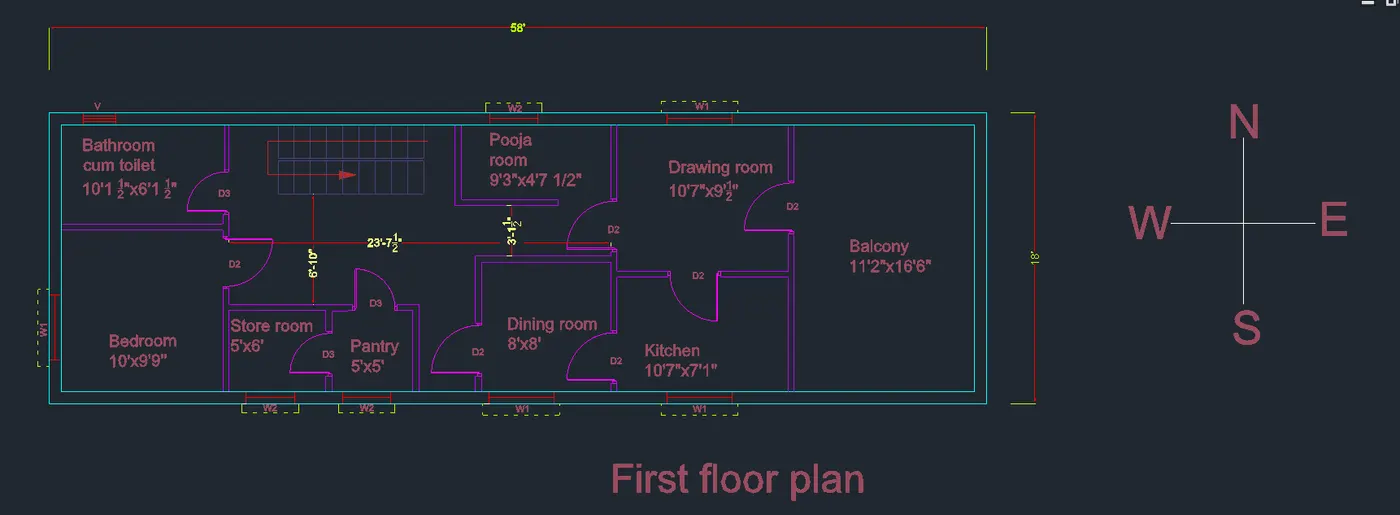
Align:Aligns objects with other objects in 2D and 3D.
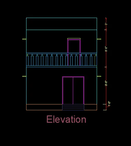
Xedges:Creates wireframe geometry from the edges of a 3D solid or surface.
Slice:Creates new 3D solids and surfaces by slicing, or dividing, existing objects.
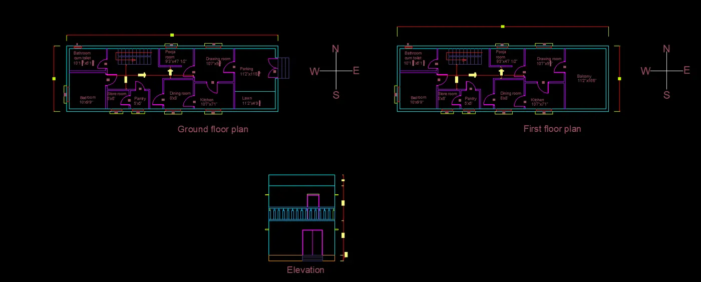
Section:Uses the intersection of a plane with 3D solids or surfaces to create a 2D region object.
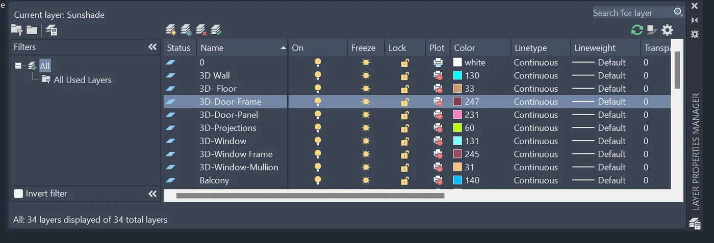
MAT:Opens the Material Browser
Materialmap:Adjusts how a texture is mapped to a face or an object.
Camera:Sets a camera and target location to create and save a 3D perspective view of objects.
RR:Creates a photorealistic or realistically shaded image of a 3D solid or surface model.
Revolve:Creates a 3D solid or surface by sweeping an object around an axis.
3Drotate:In a 3D view, displays the 3D rotate gizmo to aid in revolving 3D objects around a base point.
Rotate3D:Moves objects about a 3D axis.
RENDERING:
Rendering is the process of creating a raster image based on the 3D objects in a scene. A renderer is used to calculate the appearance of the materials attached to the objects in a scene, and how lighting and shadows are calculated based on the lights placed in a scene.Environmental and exposure settings of the renderer can be adjusted to control the final rendered image.The basic rendering workflow is to attach materials to the 3D objects of a model, place user-defined lights, add a background, and start the renderer with the RENDER command.
APPLYING MATERIALS:
1)In the command line, type MAT and then press enter. Materials browsers dialog box will appear.
2)Click on Autodesk library (expanded) and select the material category ( ex: Glass, plastic, roofing, stone, finish, metallic paint, wall covering etc).
3)Add material to document.
4)Select the objects which you want to assign the material.
5)In the Materials Browser, right-click the material to assign and choose Assign to Selection.
6)The material is assigned to the objects.
APPLYING A MATERIAL BY LAYERS:
1)Click Visualize tab; go to Materials panel (expanded); click Attach by Layer.
2)In the Material Attachment Options dialog box, drag the material from the Materials list onto a layer in the Layers list.
3)The material is assigned to all objects on the layer whose Material property is set to ByLayer. (ByLayer is the default for the Material property when you create an object.)
TO REMOVE APPILIED MATERIALS:-
1)Click Visualize tab; click Materials panel (expanded) ;click Remove Materials.
2)Select an object whose material you want to remove.
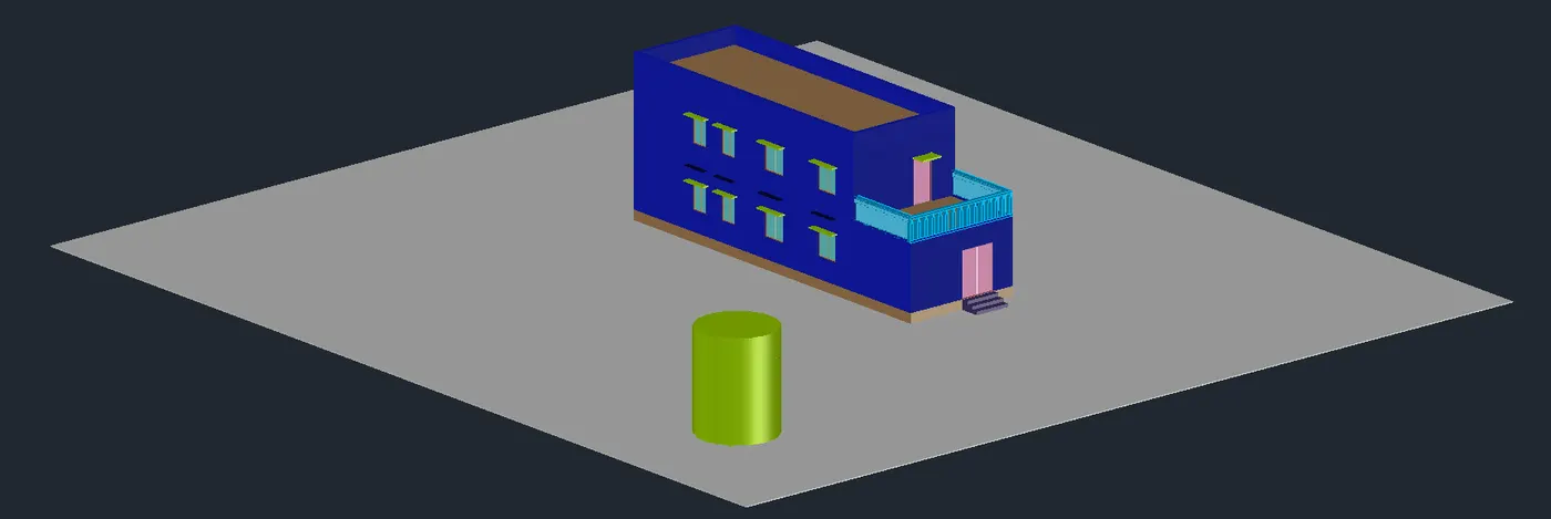
3)The material is removed from the object and replaced by the ByLayer material.
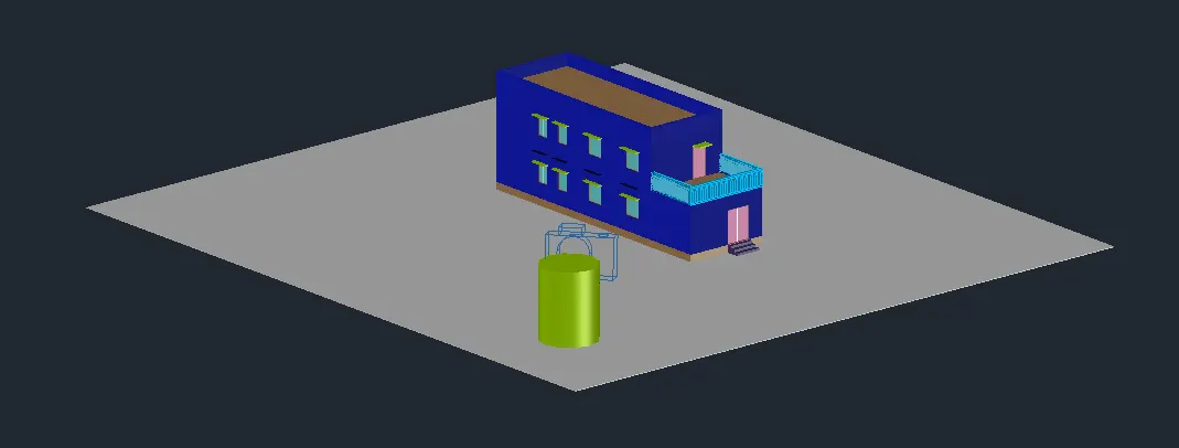
- LA
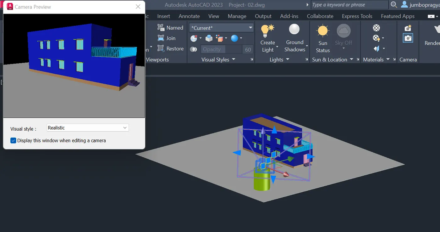
- LIMITS
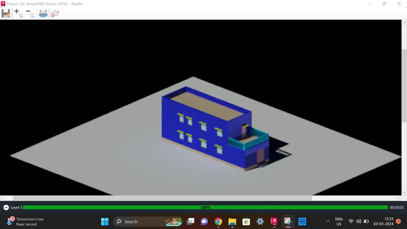
- UN
- LINE
- PL
- XL
- DT
- MLD
- DIMLIN
- DIMCONT
- H
- CO
- F
- TR
- E
- O
- EX
- B
- I
- LAYISO
The architectural drawings are sketched up in AutoCAD using the above commands.
Some basic definations :-
Built up area or plinth area : Area excluding empty space around the building is called Built up area or plinth area.
Floor plan : Floor plan is a technical drawing to scale, showing a view from above, of the relationships between rooms, spaces and other physical features at one level of a structure.
Elevation : An elevation drawing is an orthographic projection drawing that shows one side of the house.
Section : It's the drawing of a vertical cut through a building or an area of a building.
PROCEDURE -
1)Open AutoCAD software.
2)Set the units to architectural, select 'inches' in insertion scale option and select ok.
3)Using LIMITS command set lower left corner limit as (0,0) and upper right corner limit as (500',500').
4)Go to layer properties < create new layers < name the layers for reference < close.
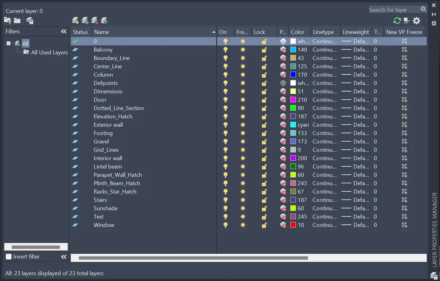
5)Using the commands LINE and DT, I have created the directions.
6)Then, using the Block command, I made it to a single block and named it as directions.
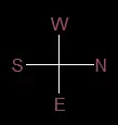
7)The buiding's main entrance is facing the East direction.
8)Starting from the east, the car parking is planned at 11'2" x 11'8 1/2" and lawn area for 11'2" x 4'9 1/2".
9)Outer walls of thickness 9'' and inner walls of thickness 4.5'' is provided.
10)Using the commands line, polyline, offset, fillet ,trim and extend, I have created my own plan for the project.
11)It is planned as per VASTU SHASTRA. Even those directions are mentioned below :
Main door : facing east
Drawing room : facing east
Kitchen : south-east
Pooja room : north-east
Stairs : north-west
Dining room : south-east
Pantry : south-west
Store room : south-west
Bedroom : south-west
Bathroom cum toilet : north-west
12)The room dimensions are also assumed as per requirement.
13)Using the line and trim command, I have provided the doors spaces as required. The door dimensions are shown below :
| DOORS | SIZES |
| D1(Main door) | 5'x7' |
| D2 | 3'x7' |
| D3 | 2'6"x6'6" |
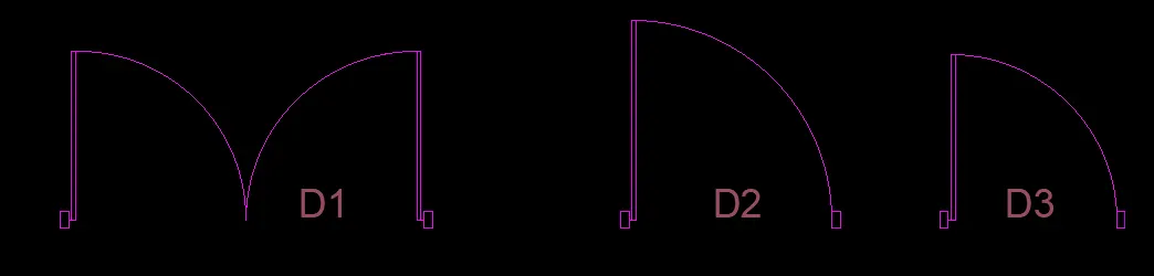
14)Using the mentioned dimensions, doors are trimmed and placed at the required door spaces.
15)Stairs are provided using line and offset command, with Tread - 1' and Rise - 6".
16)Window dimensions are shown below :
| WINDOWS/VENTILATOR | SIZES |
| W1 | 4'x4' |
| W2 | 3'x4' |
| V | 2'x2' |
17)Windows are drawn as per the dimensions mentioned above and are placed in the plan as per requirement.

18)After placing the windows sunshades are drawn.
19)Using the DText command, I have mentioned the names of all the rooms, spaces, doors, windows and dimensions of all the rooms.
20)Using the DIMLIN command, I have mentioned the dimensions in the additional spaces and changed the layer to dimensions.
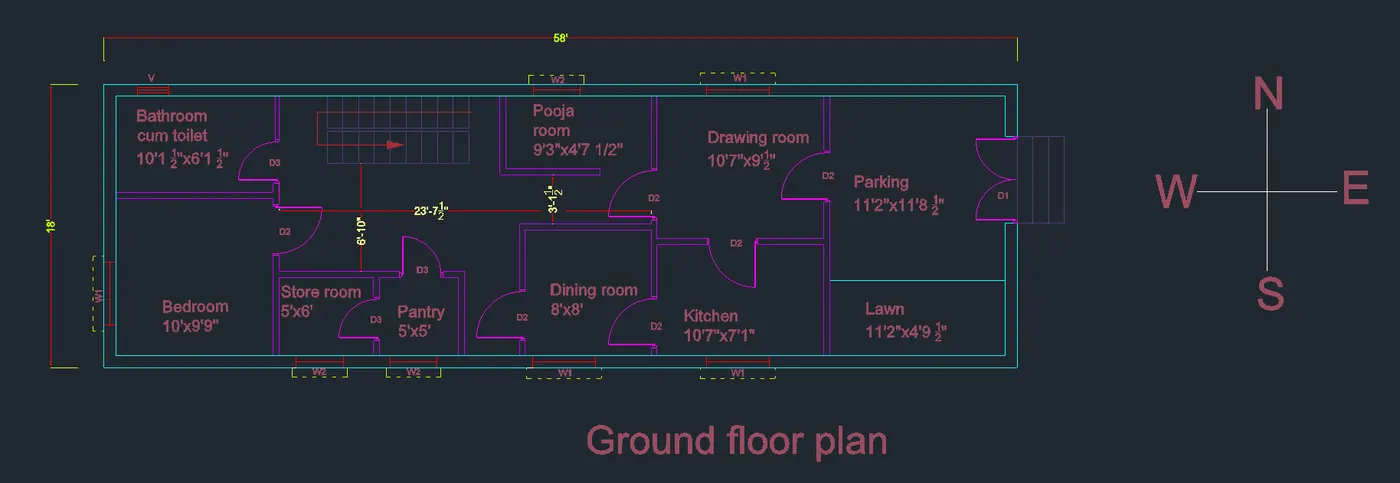
21)And in the same way first floor plan is made and the only change is that parking and lawn is replaced by balcony as shown below.
22)Using the commands line, polyline, offset, fillet, trim , I have created the Elevation.
23)I have provided chajja, parapet wall, balcony and doors as per plan.
24)The following image shows the Ground Floor plan, First Floor Plan, Front Elevation , together.
25)I have made the layers required for doing the 3D work.
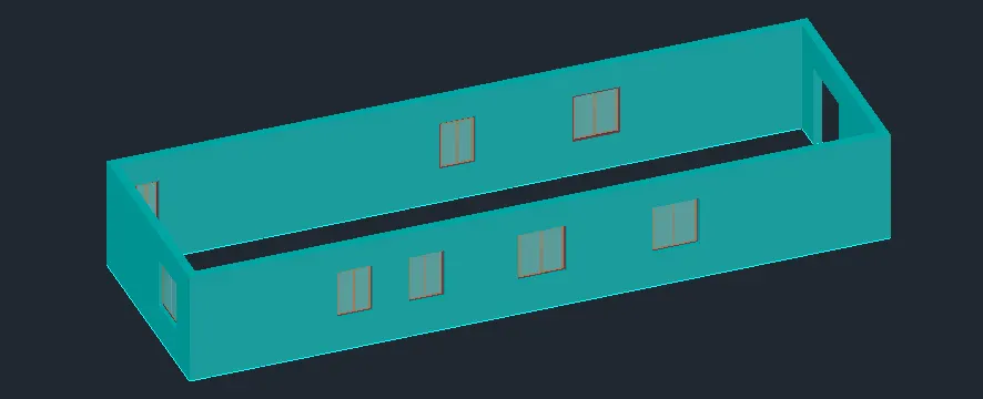
26)I turned off all the layers except exterior walls and window.
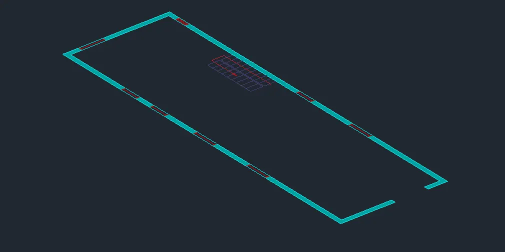
27)Using commands UCS, BO and extrude, I created the 3D walls.
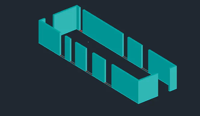
28)Now I will create opening for windows.
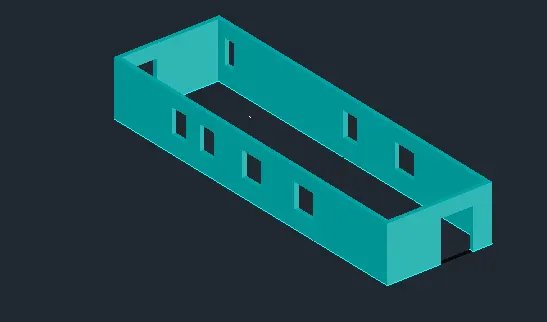
29)Now I will use UNION command so that a composite solid is created.
30)Using commands section,group,rotate 3D, boundary, subtract and explode I have created windows.
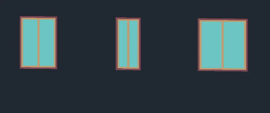
All these windows are as per plan.
31)Using commands copy, move, rotate 3D and align I have placed all the windows in the openings created earlier.
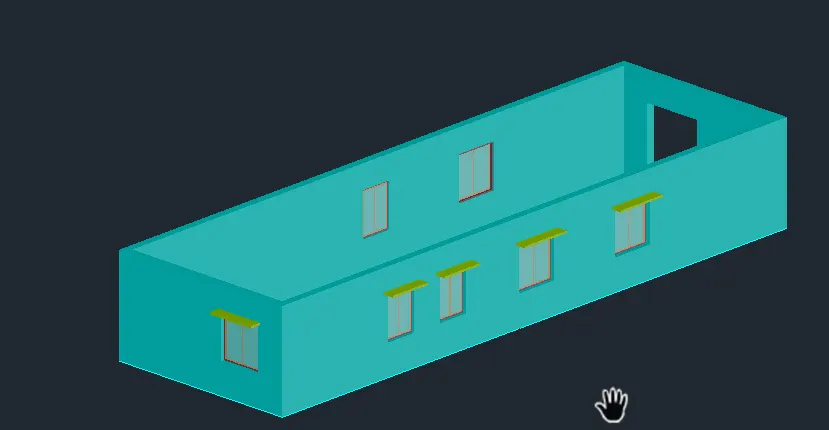
32)Using commands extrude, UCS, shademode and CO I will make projections over the windows. I will put these into projection layer.
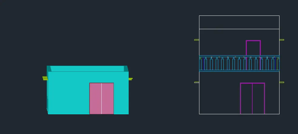
33)I will take the help of elevation and make the main door of the building.
34)I will turn off 3D wall layer; make a rectangle over the boundary wall and extrude it. Thus, plinth is created.
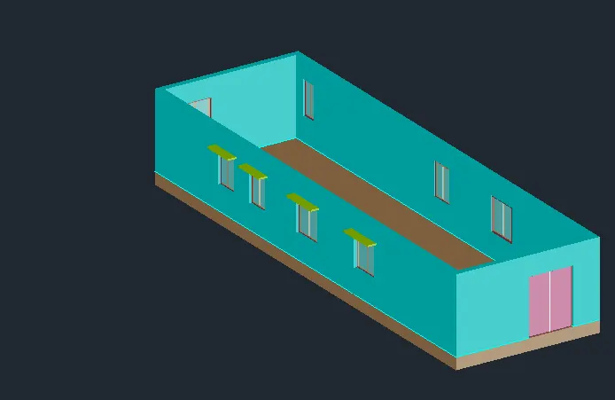
35)I will turn on interior walls layer ;create boundary and extrude it to get interior walls.
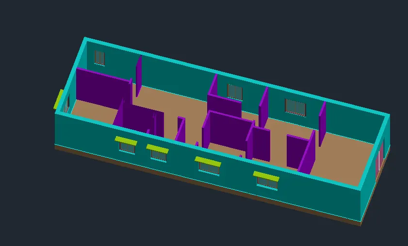
36)Now I will make a floor over the interior walls. I will make a rectangle using rec command over the inner edges of the boundary wall and extrude it.
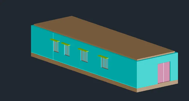
37)Using copy command, I will copy the ground floor building and place it above it. Thus I get the first floor building.
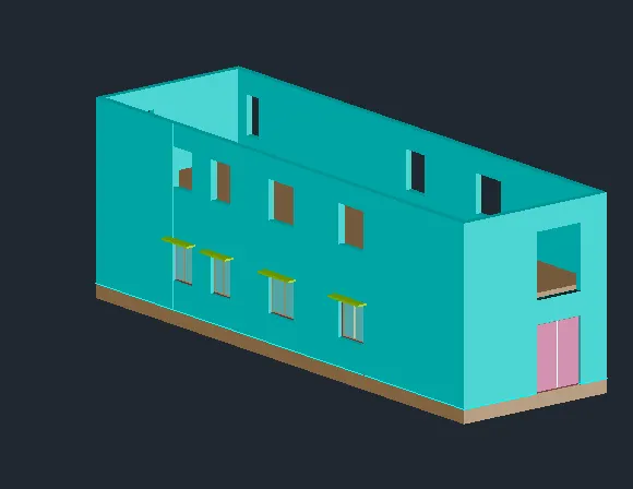
38)Using subtract command I have created space to create the balcony.
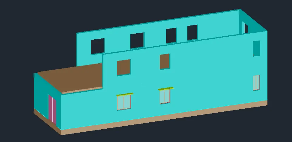
39)I have copied balcony railings from elevation to some other place using copy command and using commands array and extrude, created the balcony railings.
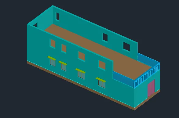
40)I have provied interior walls on the first floor by using copy command.
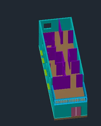
41)Now I will make a slab for the first floor.
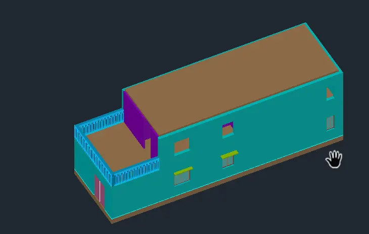
42)I made a rectangle over the edges of exterior walls; moved it to some other location using move command; finally created plinth wall using offset, subtract and extrude command.
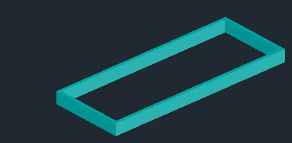
43)I will place the plinth wall over the exterior walls using move command.
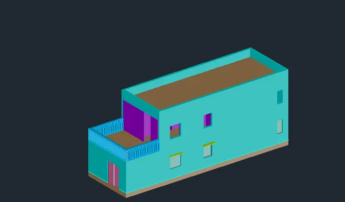
44)I have provided door at the first floor and all the windows as per plan.
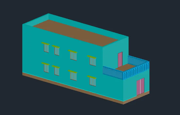
45)Using the ground floor plan and commands boundary, extrude and copy I have provided stairs at the entrance of the building.
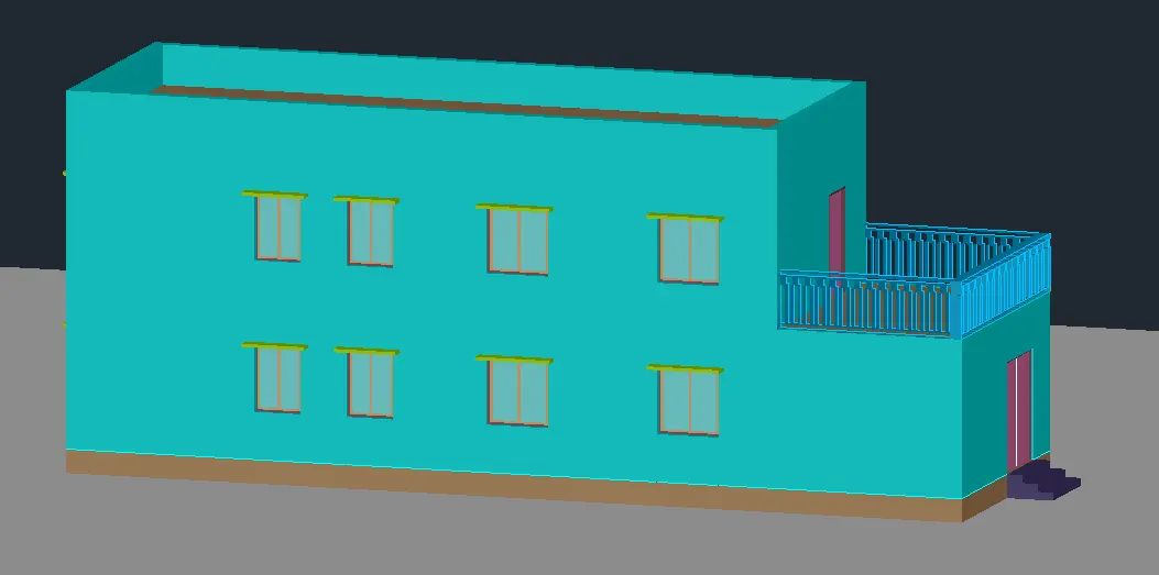
46)I have placed a chajja for the first floor door near balcony.
47)Using MATERIALS command I have applied glossy blue wall paint to the walls.
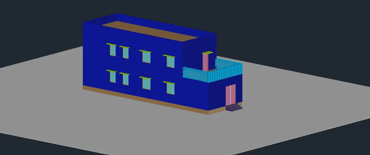
48)I have created a cylinder at the base floor for placing the camera.
49)In the command line type camera and press enter. Now place the camera over the cylinder; specify target location, give lens length as 32 mm; name the camera as "Cam 3". Press enter.
Note: lesser the lens wider the view
50)Double click over the camera to see the camera preview.
51)In the command line type rpref and press enter. Render presets manager dialog box appears. Select 'Window' in 'render in' option. Type RR in the command line and press enter to see the rendered image of the building. It is shown as under :
RESULT -
A 3 dimensional model of the residential building with a rendered view has been successfully created. Main Images explaining the result of the project are as under: