Sketch a G+1 residential plan according to Vaastu Shastra and Calculation of Loads as per IS code
Sketch a G+1 floor residential plan, according to Vaastu Shastra, and list down the names of the structural drawings required to be provided to the site for construction.
Also, assume the sizes of the structural elements (Column, Beam, Slab, etc.,) and accordingly calculate the individual corresponding loads from the members as per IS code.
AIM : To sketch a plan of G+1 floor residential building according to Vaastu Shastra and listing down the names of the structural drawings required to be provided to the construction site.
INTRODUCTION TO VAASTU SHASTRA :
Vaastu Shastra :-
- Vastu Shastra is the Ancient Indian Science of architecture and acts as a guideline to design your home in the way that enhances positive energy.
- Our nature is abundant with powerhouses of energy sources like the Sun, Wind, Moon, Water, Earth and Fire.
- Effect of sunrays, flow of winds, pull of earth's magnetic field and other such cosmic energies utilise properly to enhance the positive energy at home.
- A good home needs to radiate the right kind of energy.
- A person dwelling in a house comes under the influence of a specific energy field.
- Architectural changes are not possible for a ready to move in house.
Significance of Eight directions :-
- Four cardinal direction are North, South, East and West.
- Four intercardinal direction are North-east, North-west, South-east and South-west.
- Each direction signifies an aspect of life and is governed by various gods as per Vaastu Shatra.
- North - Wealth
- South - Dharma
- West and East - Overall prosperity
Basic principles of Vastu Shastra :-
Shape :-
Rooms should be preferably be square or rectangle.
Room Basics :-
Rooms should be airy, well lit, bright and clean.
Home center :-
Centre of the house should be an empty space.
Stairs and Furniture :-
Heavy furniture should be kept in the south-west direction.
Water :-
Avoid keeping plants and water features in the bedroom.
Dining Table :-
Dining space should be near the kitchen and not near the main door.
Mirror placement :-
Mirror facing the bed is strictly not allowed. Mirrors in the bedroom need to be placed in such a way that the bed cannot be seen.
Auspicious directions as per Vastu Shastra :-
Kitchen :-
South-east is the best direction fo kitchen.
North-east to be avoided.
Staircase :-
South-west is the best for stairs.
North-east to be avoided.
Toilet :-
North-west is the best.
North-east to be avoided.
Master Bedroom :-
South-west is the best.
Guest Room :-
North-west is the best.
Living Room :-
North-west is the best.
Over Head Tanks :-
West is the best.
Under ground Tanks :-
North-east is the best.
South-west to be avoided.

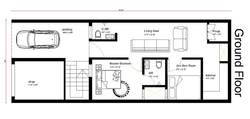
(ALL DIEMENSIONS ARE IN FEET & INCHES)
Dimensions of Ground Floor Plan:
Living room = 21'6" x 8' 4 1/2"
Kitchen room = 6'0" x 8'9"
Master bedroom = 12'0" x 9' 7 1/2"
Bathroom = 5'0" x 1'1/2"
2nd Bed room = 8'0" x 9' 7 1/2"
C- Bathroom = 5'6" x 4'0"
Pooja room = 4'6" x4'6"
shop = 11'9" x 9'3"
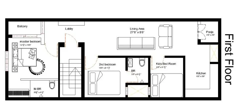
(ALL DIEMENTIONS ARE IN FEET & INCHES)
Dimensions of First Floor Plan:
Living area = 27'6" x 8'6"
Master bedroom = 12'1 1/2" x 10'0"
Second bedroom = 10'0" x 9'7 1/2"
Kids bedroom = 8'0" x 9'7 1/2"
M- bathroom = 6'9 1/2" x 4'1 1/2"
Bathroom = 5'0" x 6'1 1/2"
kitchen = 6'0" x 8'9"
Poojaroom = 4'6" x 4'6"
Vastu Shastra followed during planning:
- Entrance of the house is provided in the east direction which is the symbol of progress in life.
- Living room is placed in north east direction.
- Master bedroom is placed in south west position this direction brings good health and prosperity.
- Kitchen is placed in south east direction.
- Study room is placed in east direction.
- Staircase is placed at Northwest corner.
- Bathroom, WC and toilet is placed in West direction.
Concept of vaashu,
List of drawings provided at the construction project:
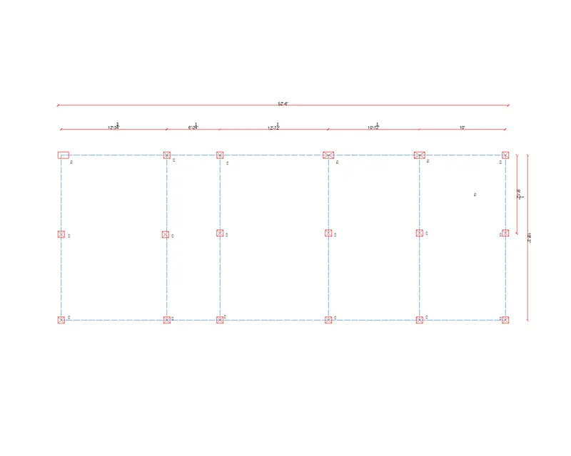
Centre line drawing:
- It is used for the marking of the columns at the site during first stage where soil is excavated for the footings.
- It contains all the grid positions and column demensions and numbering (provided outside of column).
- It is a important which is first issued to the site.
- Grid to grid distance and structural notes and the legends are mandatory.
Footing and column layout with reinforcement details:
- It shows the size and dimensions of the footing from center of the columns and also with reference to the gridlines.
- Here we can check weather there is a footing clash from which we can manage by altering the dimension is required directions so there is no clash obtained.
- Grid to grid distance and structural notes and the legends are mandatory.
Column schedule with reinforcement details:
- Typical footing layout details are provided.
- Reinforcement details of the column is required.
- For respective columns provided the column size and column reinforcement detail and strirrups details is also to be provided.
- Footings also has to be categorized.
Plinth beam layout with reinforcement details:
- Any details of the floating column.
- Where the typical beams connecting the columns.
- Beam numbering and grouping is shown.
First floor beam layout with reinforcement details:
- Provide the location of the sunken slab with its sunken thickness.
- Floor beams and slab dimensions are provided commonly.
- Level Difference if required should be presented.
- Reinforecement details of the slab is mustCrank position should be indicated.
- Details of the main and distribution reinforcement.
- Where the typical beams connecting the columns.
Lift pit and head room reinforcement details:
- It covers the area of the lift pit area describing the thickness of the RCC wall and waterproof wall.
- And provision of the lintel beam is mandatory.
- Sectional view of the lift pit is also important.
- Lift pit and headroom should be in same position.
- Load should be considered before the lift room.
DATA AS DIAGRAM:
- No, OF FLOORS = 2 Nos
- FLoor Hight = 3 m
- Building Hight = 7.5 m
- Beam size = (`0.23 X 0.23`)
- long wall = 3 NOS EACH FLOOR
- short wall = 6 NOS EACH FLOOR
- Column
- C1 = (`0.23 X 0.23`) 15 NOS EACH FLOOR
- C2 = (`0.23 X 0.38`) 3 NOS EACH FLOOR
- Slab = (`16.0 X 6.0 X 0.15`)
load Calculations:
|
Dead load IS 875:1987, Part 1 for Dead load |
||||||||
|
S.no |
L |
B |
H |
Qty |
Vol of beam |
Unit wt KN/M3 |
Load KN |
|
|
1 |
Beam |
|||||||
|
a |
long wall |
|||||||
|
a.1 |
lintel |
16.0 |
0.23 |
0.23 |
3 |
2.54 |
25 |
63.50 |
|
a.2 |
Ground floor |
16.0 |
0.23 |
0.23 |
3 |
2.54 |
25 |
63.50 |
|
a.3 |
1st floor |
16.0 |
0.23 |
0.23 |
3 |
2.54 |
25 |
63.50 |
|
b |
Short wall |
|||||||
|
b.1 |
lintel |
5.6 |
0.23 |
0.23 |
6 |
1.79 |
25 |
44.76 |
|
b.2 |
Ground floor |
5.6 |
0.23 |
0.23 |
6 |
1.79 |
25 |
44.76 |
|
b.3 |
1st floor |
5.6 |
0.23 |
0.23 |
6 |
1.79 |
25 |
44.76 |
|
|
324.78 |
|||||||
|
2 |
Column |
|||||||
|
a |
Ground floor |
|||||||
|
a.1 |
C-1 |
0.23 |
0.23 |
3 |
15 |
2.38 |
25 |
59.51 |
|
a.2 |
C-2 |
0.23 |
0.4 |
3 |
3 |
0.83 |
25 |
20.70 |
|
b |
1st floor |
|||||||
|
b.1 |
C-1 |
0.23 |
0.23 |
3 |
15 |
2.38 |
25 |
59.51 |
|
b.2 |
C-2 |
0.23 |
0.4 |
3 |
3 |
0.83 |
25 |
20.70 |
|
|
160.43 |
|||||||
|
3 |
Slab (Full Area) |
|||||||
|
|
16 |
6.1 |
0.15 |
1 |
14.64 |
25 |
365.99 |
|
|
|
A |
365.99 |
||||||
|
|
Deduction value |
|||||||
|
a |
long wall |
|||||||
|
a.2 |
Ground floor |
16.0 |
0.23 |
0.15 |
3 |
1.66 |
25 |
41.42 |
|
a.3 |
1st floor |
16.0 |
0.23 |
0.15 |
3 |
1.66 |
25 |
41.42 |
|
b |
Short wall |
|||||||
|
b.2 |
Ground floor |
5.6 |
0.23 |
0.15 |
6 |
1.17 |
25 |
29.19 |
|
b.3 |
1st floor |
5.6 |
0.23 |
0.15 |
6 |
1.17 |
25 |
29.19 |
|
|
B |
141.21 |
||||||
|
|
Grand Load of Slab A-B |
224.79 |
||||||
|
4 |
Brick wall Unit Weight of Building Materials used in construction works as per IS 875 (Part-1) |
|||||||
|
a |
Ground floor |
68.7 |
0.23 |
2.75 |
1 |
43.47 |
20 |
869.43 |
|
b |
1st floor |
77.2 |
0.23 |
2.75 |
1 |
48.84 |
20 |
976.71 |
|
c |
parpet Wall |
145 |
0.23 |
1 |
1 |
33.35 |
20 |
667.00 |
|
d |
Over Head room |
8.23 |
0.23 |
1 |
1 |
1.89 |
20 |
37.87 |
|
live load IS 875:1987, Part 2 for Live load |
||||||||
|
L |
B |
H |
Qty |
Vol of beam |
Unit wt KN/M3 |
Load KN |
||
|
1 |
Beam |
|||||||
|
a |
long wall |
|||||||
|
a.1 |
lintel |
16.0 |
0.23 |
0.23 |
3 |
2.54 |
2 |
5.08 |
|
a.2 |
Ground floor |
16.0 |
0.23 |
0.23 |
3 |
2.54 |
2 |
5.08 |
|
a.3 |
1st floor |
16.0 |
0.23 |
0.23 |
3 |
2.54 |
2 |
5.08 |
|
b |
Short wall |
|||||||
|
b.1 |
lintel |
5.6 |
0.23 |
0.23 |
6 |
1.79 |
2 |
3.58 |
|
b.2 |
Ground floor |
5.6 |
0.23 |
0.23 |
6 |
1.79 |
2 |
3.58 |
|
b.3 |
1st floor |
5.6 |
0.23 |
0.23 |
6 |
1.79 |
2 |
3.58 |
|
|
25.98 |
|||||||
|
2 |
Slab (Full Area) |
|||||||
|
|
16.0 |
6.1 |
0.15 |
1 |
14.64 |
2 |
29.28 |
|
|
29.28 |
||||||||
Wind load calculation:
Wind load is designed only when the height of the building exceeds 10m.
The height of designed building is 7.5m which is less than 10m.
So, the calculation of wind load is not required.
RESULT:
The plan is prepared by the Vaastu shastra concept considering all the principles and considerations of Vaastu shastra.,The load calculations are done as per the IS code considerations.