Creation of geometries by Coordinate system methods using AutoCad
AIM:
1.Create the geometries from P1 to P2 using all the coordinates system methods. And we need to use line tool, and find the missing dimensions.
2.Civil related problems- Draw the profile and the trusses using any coordinate system methods. The dimensions are there for references.
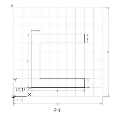
- Select line tool from the ribbon tab/write line in command box,it will show "specify the first point ".
- Enter the first point as (2,1)
- Next, the command as to enter next point,(8,1) (8,2) (3,2) (3,6) (8,6) (8,7) (2,7)
- Specify the next point as(2,1),else click on the close in command prompt.
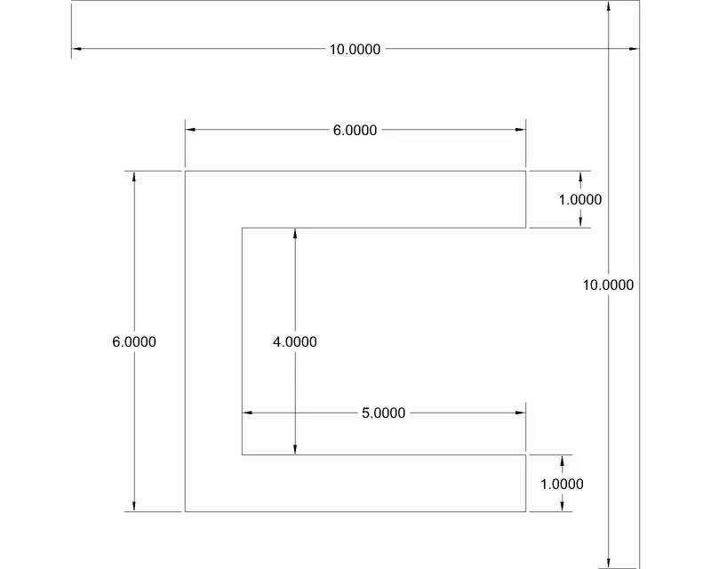
2.RELATIVE RECTANGULR CO-ORDINATE SYSTEM:
- Select the line tool by entering line command in the command tab.
- Specify the starting co-ordinate of points (1 as 2,1)in command line.
- Specify the next co-ordinate of points is (2,@6,0) (3,@0,1) (4,@-5,0) (5,@0,4) (6,@5,0) (7,@0,1) (8,@-6,0) in command line.
- Click 'CLOSE' on the command line.
3.RELATIVE POLAR CO-ORDINATE SYSTEM:
- Select the line tool by entering line command in command tab.
- specify the starting co-ordinates (1 as 2,1) (2 as @ 6<0) (3 as @ 1<90) (4 as @ 5<180) (5 as@ 4<90) (6 as @5<0) (7 as @1<90) and (8 as @6<180 ) in command line.
- Click 'CLOSE' on the command line.
4.DIRECT DISTANCE ENTRY METHOD:
- Enter the line command tab.
- And the length of all points used in the command line to wards the directions.
- Enter the 'CLOSE' on the command line.
RESULT:
Create the geometries for P2 using all the coordinates system methods:
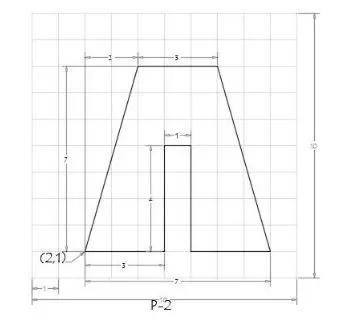
- Select line tool from the ribbon tab/write line in command box,it will show "specify the first point ".
- Enter the first point as (2,1)
- Next, the command as to enter next point,(5,1) (5,5) (6,5) (6,1) (9,1) (7,8) (4,8)
- Specify the next point as(2,1),else click on the close in command prompt.
2.RELATIVE RECTANGULR CO-ORDINATE SYSTEM:
- Select the line tool by entering line command in the command tab.
- Specify the starting co-ordinate of points (1 as 2,1)in command line.
- Specify the next co-ordinate of points is (2 as 3,0) (3 as @0,4) (4 as 1,0) (5 as @0,-4) (6 as @3,0) (7 as @-2,7) (8 as @-3,0) in command line.
- Click 'CLOSE' on the command line.
3.RELATIVE POLAR CO-ORDINATE SYSTEM:
- Select the line tool by entering line command in command tab.
- specify the starting co-ordinates (1 as 2,1) (2 as @ 3<0) (3 as @ 4<90) (4 as @ 1<0) (5 as@ 4<270) (6 as @3<0) (7 as @7<106) and (8 as @3<180 ) in command line.
- Click 'CLOSE' on the command line.
4.DIRECT DISTANCE ENTRY METHOD:
- Enter the line command tab.
- And the length of all points used in the command line to wards the directions.
- Enter the 'CLOSE' on the command line.
RESULT:
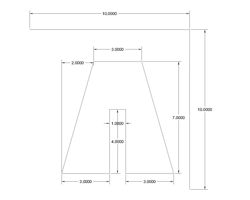
Create the geometries for P4 - P10 Using any coordinates system methods.
Steps creating the geometry in p-4 using absolute co-ordinate system method.
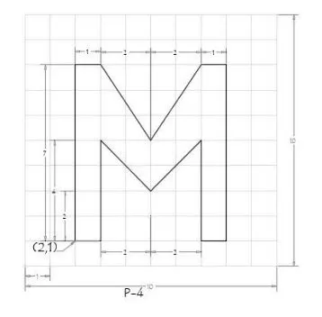
- Select line tool from the ribbon tab/write line in command box,it will show "specify the first point ".
- Enter the first point as (2,1)
- Next, the command as to enter next point,(3,1) (3,5) (5,3) (7,5) (7,1) (3,1) (8,8) (7,8) (5,5) (3,8) (2,8)
- Specify the next point as(2,1),else click on the close in command prompt.
RESULT:
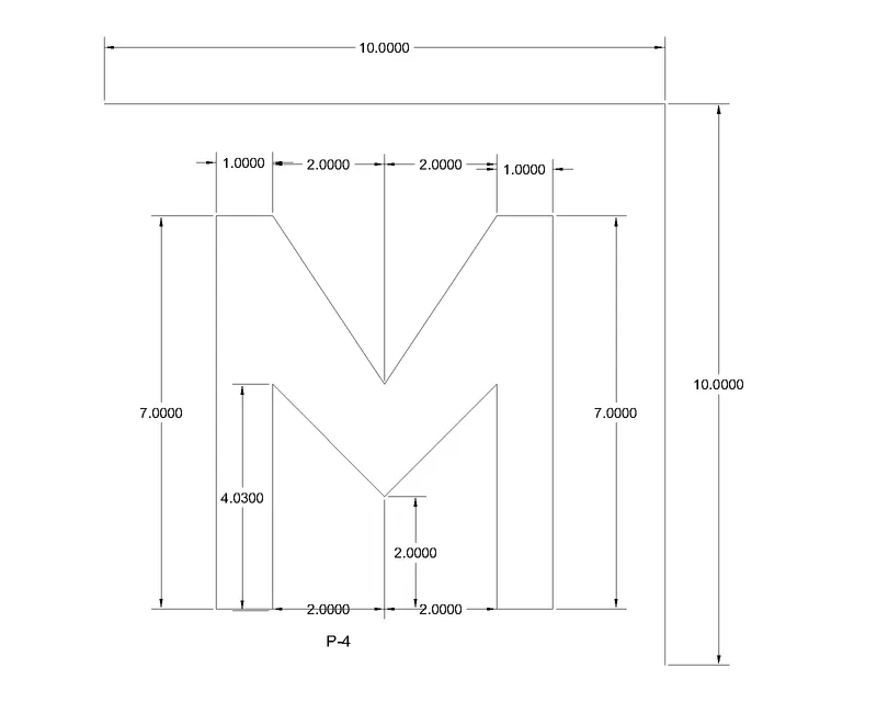
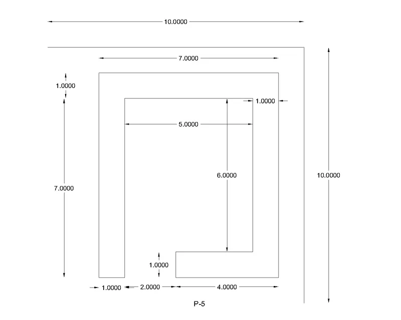
Create the geometries for P5 using Relative rectangular co-ordinates system methods:
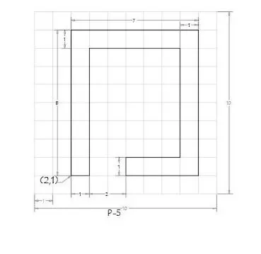
1.RELATIVE RECTANGULR CO-ORDINATE SYSTEM:
- Select the line tool by entering line command in the command tab.
- Specify the starting co-ordinate of points (1 as 2,1)in command line.
- Specify the next co-ordinate of points is (2 as 3,0) (3 as @0,4) (4 as 1,0) (5 as @0,-4) (6 as @3,0) (7 as @-2,7) (8 as @-3,0) in command line.
- Click 'CLOSE' on the command line.
RESULT:
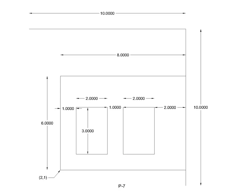
Creating the geometry in p-7 using absolute co-ordinate system method.
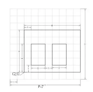
- Select line tool from the ribbon tab/write line in command box,it will show "specify the first point ".
- Enter the first point as (2,1)
- Next, the command as to enter next point,(2,1) (10,1) (10,7) (2,7)
- Click on the close in command prompt.
- Select line tool from the ribbon tab/write line in command box,it will show "specify the first point ".
- Next, the command as to enter next point,(3,2) (5,3) (5,5) (3,5)
- Click on the close in command prompt.
- Select line tool from the ribbon tab/write line in command box,it will show "specify the first point ".
- Next, the command as to enter next point,(6,2) (8,2) (8,5) (5,6)
- Click on the close in command prompt.
RESULT:
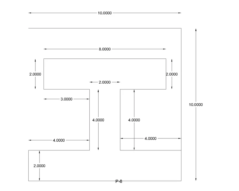
Create the geometries for P-8 using Relative rectangular co-ordinates system methods:
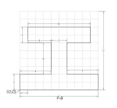
1.RELATIVE RECTANGULR CO-ORDINATE SYSTEM:
- Select the line tool by entering line command in the command tab.
- Specify the starting co-ordinate of points (1 as 0,0)in command line.
- Specify the next co-ordinate of points is (2 as @10,0) (3 as @0,2) (4 as @-4,0) (5 as @0,4) (6 as @3,0) (7 as @0,2) (8 as @-8,0) (9 as @0,-2) (10 as @0,-2) (11 as @0,-4) (12 as @-4,0)in command line.
- Click 'CLOSE' on the command line.
RESULT:
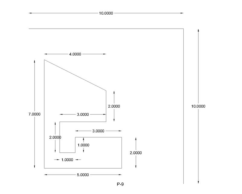
Creating the geometry in p-9 using absolute co-ordinate system method:
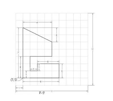
- Select line tool from the ribbon tab/write line in command box,it will show "specify the first point ".
- Enter the first point as (1,1)
- Next, the command as to enter next point,(6,1) (6,3) (3,3) (3,2) (2,2) (2,4) (5,4) (5,6) (1,8)
- Specify the next point as(1,1),else click on the close in command prompt.
RESULT:
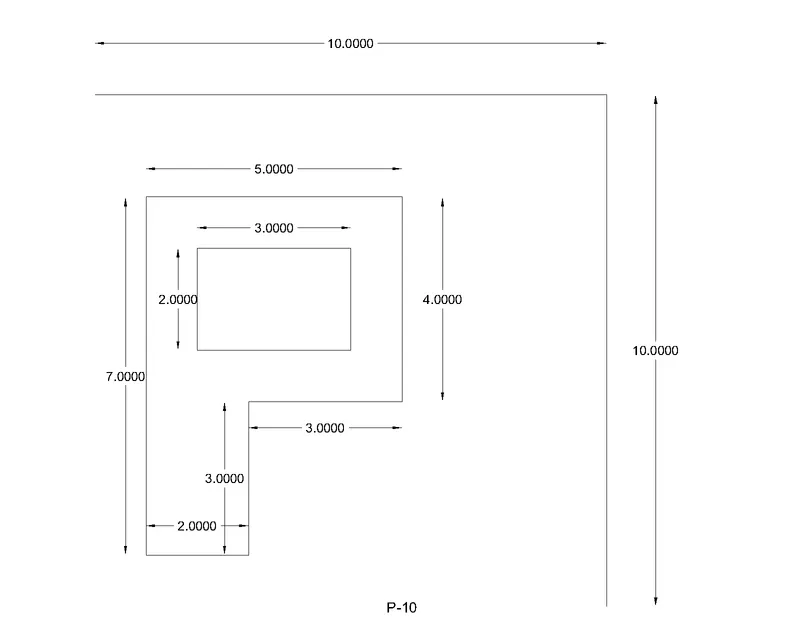
Creating the geometry in p-10using Relative polar co-ordinate system method:
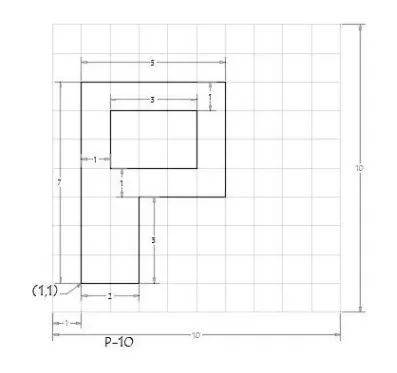
RELATIVE POLAR CO-ORDINATE SYSTEM:
- Select the line tool by entering line command in command tab.
- specify the starting co-ordinates (1 as 1,1) (2 as @ 2<0) (3 as @ 3<90) (4 as @ 3<0) (5 as @ 4<90) (6 as @5<180) (7 as @5,2) and (8 as @3<0) (9 as @2<90) (10 as @3<180) in command line.
- Click 'CLOSE' on the command line.
RESULT:
(B) CIVIL REALTED PROBLEMS:- DRAW THE PROFILE AND THE TRISSES USING ANY CO-ORDINATE SYSTEM METHODS:
The dimensions are there for references,
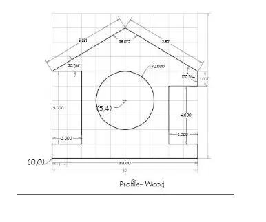
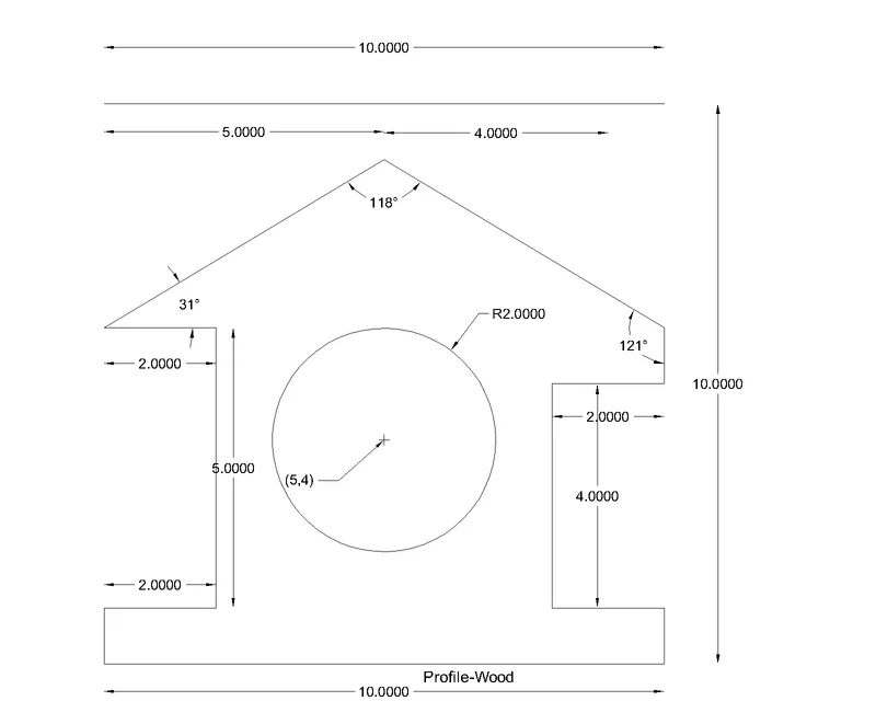
CREATING THE WOOD PROFILE USING DIRECT DISTANCE ENTRY METHOD:
PROCEDURE:
- Select the Line tool by entering 'LINE' command in the command tab.
- Specify the starting coordinate of point 1 as 0,0 in the command line.
- Enter the length of point 2 as 10 in the command line towards +ve x-axis.
- Enter the length of point 3 as 1 in the command line towards +ve y-axis.
- Enter the length of point 4 as 2 in the command line towards -ve x-axis.
- Enter the length of point 5 as 4 in the command line towards +ve y-axis.
- Enter the length of point 6 as 2 in the command line towards +ve x-axis.
- Enter the length of point 7 as 831 in the command line at an angle of <149.036 from +ve x-direction while keeping polar tracking on.
- Enter the length of point 8 as 5.831 in the command line at an angle of <210.964 from +ve x-direction while keeping polar tracking on.
- Enter the length of point 9 as 2 in the command line towards +ve x-axis.
- Enter the length of point 10 as 5 in the command line towards -ve y-axis.
- Enter the length of point 11 as 2 in the command line towards +ve x-axis.
- Click 'Close' on the command line.
- Select the Circle tool by entering 'CIRCLE' command in the command tab.
- Specify centre point of circle as 5,4.
- Specify radius of circle as 2.
RESULT:
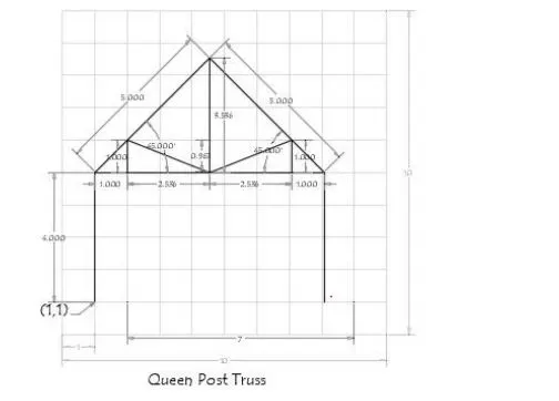
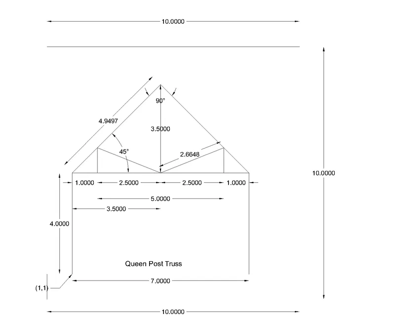
CREATING THE QUEEN POST TRUSS USING RELATIVE RECTANGULAR CO-ORDINATES SYSTEM:
PROCEDURE:
- Select the Line tool by entering 'LINE command in the command tab.
- Specify the starting coordinate of point 1 as 1,1 in the command line.
- Specify the next coordinate of point 2 as @4,0in the command line.
- Specify the next coordinate of point 3 as @3.536,3.536 in the command line.
- Specify the next coordinate of point 4 as @3.536,-3.536 in the command line. vi. Specify the next coordinate of point 5 as @0,-4 in the command line.
- Press 'Esc' to cancel the LINE command.
- Select the Line tool again by entering 'LINE' command in the command tab. ix. Join the points 2 and 4. x. Press 'Esc' to cancel the LINE command. xix. Specify the next coordinate of point 10 as @0,-1 in the command line. xx. Press 'Esc' to cancel the LINE command. xxi. Select the Line tool again by entering 'LINE' command in the command tab.
- Select the Line tool again by entering 'LINE' command in the command tab.
- Specify the next coordinate of point 6 as 4.536,5 in the command line. xiii. Specify the next coordinate of point 7 as @-2.536,1 in the command line.
- Specify the next coordinate of point 8 as @0,-1 in the command line.
- Press 'Esc' to cancel the LINE command. xvi. Select the Line tool again by entering 'LINE' command in the command tab.
- Specify the coordinate of point 6 as 4.536,5 in the command line.
- Specify the next coordinate of point 9 as @2.536.1 in the command line.
- Join points 3 and 6
- Press Esc' to cancel the LINE command.
RESULT:
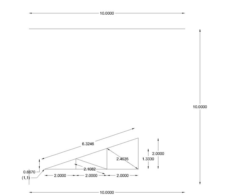
CREATING THE MONO PITCH USING ABSOLUTE CO-ORDINATE SYSTEM:
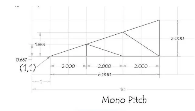
PROCEDURE:
- Select the Line tool by entering 'LINE' command in the command tab.
- Specify the starting coordinate of point 1 as 1,1 in the command line.
- Specify the next coordinate of point 2 as 7,1 in the command line.
- Specify the next coordinate of point 3 as 7,3 in the command line.
- Click 'Close' on the command line.
- Select the Line tool by entering 'LINE' command in the command tab.
- Specify the next coordinate of point 4 as 3,1 in the command line.
- Specify the next coordinate of point 5 as 3,1.667 in the command line.
- Specify the next coordinate of point 6 as 5,1 in the command line.
- Specify the next coordinate of point 7 as 5,2.333 in the command line.
- Specify the next coordinate of point 8 as 7,1 in the command line.
- Press 'Esc' to cancel the LINE command.
RESULT: