Sketch a G+1 residential plan according to Vaastu Shastra and Calculation of Loads as per IS code
1Q. Sketch a G+1 floor residential plan, according to Vaastu Shastra, and list down the names of the structural drawings required to be provided to the site for construction.
Also, assume the sizes of the structural elements (Column, Beam, Slab, etc.,) and accordingly calculate the individual corresponding loads from the members as per IS code.
Ans.
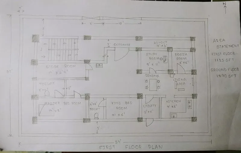
A. Brief Explanation
i. Above plan is the first floor plan of the building with in a total area of 54’ x 35’
ii. Due to the By-laws minimum setbacks are left around the building. Which can be seen in the above plan.
iii. All the Exterior wall and compound wall of the buildings are 9” thickness or 230mm thickness which includes plastering.
iv. Few areas like Toilets are provided with less weight and less thickened walls like 5” or 125mm wall
v. The staircase specifications are Rise = 15cm, Thread = 21cm, total staircase length including landing slab = 3.1m and width = 2m
vi. The centre part of the floor is kept empty as it is the Brahmasthan
vii. The above Floor plan is drafted according to the Vaastu and guidelines learned from Skill Lync and below Vaastu Chart.
B. Important structural drawings for a project
i. Centre line drawing
ii. Footing and column layout with reinforcement details.
iii. Column schedule with reinforcement details
iv. Plinth beam layout with reinforcement details.
v. First floor beam layout with reinforcement details.
vi. First floor slab layout with reinforcement details.
vii. Lift pit and Headroom reinforcement details.
i. Centre line drawing
These drawing are used for marking the columns at site at first stage of construction , by this line and reference the site engineer mark the column positions in the ground and that is where the footing excavation starts. Centre line drawing is the mandatory drawing to be provided to the site at first place from this initial drawing, the construction starts.
ii. Footing and column layout with reinforcement details
These drawings consists of the footing dimensions and the size of excavation to be done for every footing and PCC, the column placements, footing placements with reference to grid etc., can be carried out. The thickness of the soil filling, PCC and footing depth from ground surface etc., can be known.
iii. Column schedule with reinforcement details
The column schedule drawing consists of the reinforcement details for the different columns and lap length to be provided, the no. of rebar, cover spacing, dia. of rebar and spacing of lateral ties and dia. of lateral ties are provided.
iv. Plinth beam layout with reinforcement details
After backfilling and consolidation of footings are done, then the plinth beam reinforcement detail plan is to be provided. In this drawing, the detailed drawing of plinth beam connecting the columns are to be provided. The reinforcement details of the plinth beam is provided with the rebar dia. no. of bars and stirrups.
v. First floor beam layout with reinforcement details
The beam layout comprises of the structure size, reinforcement details, space cover details, rebar in compression zone and tension zone with dia., spacing and length. Stirrups dia., spacing and development length of rebar is provided.
vi. First floor slab layout with reinforcement details
The slab layout comprises of the slab size, one way or two way reinforcement details, space cover details, rebar of main reinforcement and distribution reinforcement dia., spacing and length.
vii. Lift pit and Headroom reinforcement details
The lift hook load is to be taken from the vendor so that the lift or headroom slab is designed in such a way. The head room reinforcement layout consists of the beams and slabs with rebars dia., number of rebar, spacing, and stirrups for beams are given.
C. Calculation of Loads
Assuming the Dimensions of
Columns = 0.45m x 0.6m
Beams = 0.3m x 0.45m
Slab thickness = 0.15m
Dead Load:
i) Columns weight
Size of column = 0.45m x 0.6m x 3.3 m (column height equal to height of the wall)
Volume of a single column = 0.891 m3
No. of columns in whole = Consider columns placed at corners and two brick wall intersections = 22 columns
Volume of all columns = 0.891 m3 x 22 no. = 19.6 m3
Unit Weight of RCC = 25 kN/m3
Weight of all columns = 25 x 19.6 = 490 kN
ii) Beams Weight
Size of Beam = 0.3m x 0.45m
Length of beam run = 110.21m
Volume of all beams = 0.3m x 0.45m x 110.21m = 14.88 m3
Unit weight of RCC = 25kN/m3
Weight of all Beams = 14.88x 25 = 372 kN
iii) Brick wall weight
Size of exterior brick wall = 0.25m x 3.2 m
Size of internal brick wall = 0.125m x 3.2 m
Volume of 230mm brick wall = 0.25m x 3.2 m x 98.3 m = 78.64 m3
Volume of 125mm brick wall = 0.125m x 3.2 m x 11.9 m = 4.76 m3
Total Volume of Brick wall = 83.4m3
Unit weight of Brick Masonry = 20kN/m3
Weight of all Brick walls = 56.4 x 20 = 1668 kN
iv) Slab weight
Area of the all rooms including sit-out area = 120.40 m2
Thickness of the slab = 125mm
Volume of the slab = 15.06m2
Unit weight of the RCC = 25 kN/m2
Weight of the Slab = 25 x 15.06 = 376.35 kN
v) Flooring Weight
Area of flooring or carpet area = 95 m2
Thickness of the flooring = 50mm
Volume of Flooring = 102m x 0.05m = 4.75 m3
Unit weight of the flooring = 0.6 to 1.2 kN/m3 (take 1 kN/m3)
Weight if the flooring = 4.75 x 1 = 4.75kN
Dead Load = Total weight of beam weight + column weight + Brick wall weight + Slab weight + Flooring weight = 490 kN + 372 kN + 1668 kN + 376.35 kN +4.75kN = 2911.1kN
Live Load
i) The total area of the house or slab = 120.4 m2
ii) As per IS: 875 part II, the minimum live load for floors in houses, Hospital wards, dormitories = 2 kN/m2
iii) So, the imposed load on the floor and slab = 2 kN/m2 = 4 kN/m2
iv) Total live load = 4 kN/m2 x 120.4 m2 = 481.6 m2
Live load or Imposed Load = 481.6 m2
Wind Load
As per the IS: 875:1987, the wind load is only considered for the buildings above 10m
So, no requirement of calculation of wind load
Seismic load
b) Seismic Coefficient Method (SCM) – Equivalent static method
The seismic co-efficient method is based on the assumptions like the structure is rigid, fixidity of the structure to the ground is perfect, during ground motion all points experience same accelerations, Effects of earthquake are considered as equivalent forces.
1: Calculation of design of seismic base shear
The design base shear is the sum of lateral forces applied at all levels that are finally transferred to ground,
VB = W x Ah
Where,
W = Seismic weight of the building
Ah = Horizontal seismic coefficient
Where
Ah = (ZISa / 2Rg)
Provided for any structure with T<0.1S, the value of Ah will not taken less than Z/2 whatever be the value if I/R
Where,
i) Z= zone factor
ii) I = importance factor
iii) R= Response Reduction Factor
iv) Sa/g = Average response acceleration coefficient
v) T= undamped natural period of the structure
Selecting Necessary data from the IS code 1893: 2002
Z= 0.16
I = 1
R= 3
Sa/g = 0.85
T = 1
Ah = (0.16x1x 0.85/ 2 x 3) = 0.02267
VB = W x Ah
Where, W= weight of the structure,
We have the loads of First floor , then multiply with the no. of floors to get the weight of the building 2911KN x 2 floors = 5822 kN
VB= 5822 x 0.02267 = 131.98 kN/ m2
No requirement or necessity of Multiplying or applying partial safety factor of load combination