Creating a Floor plan, Footing detail and Isometric view using AutoCad
Creating a Floor plan, Footing detail and Isometric view using AutoCAD
1Q.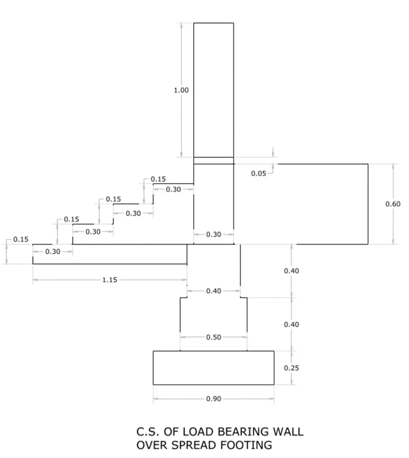
Ans.
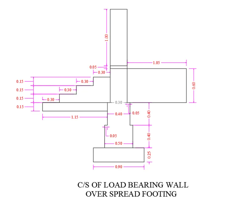
AIM:- To draw the above shown Cross section of load bearing wall over spread footing in AutoCAD
Introduction:- The load bearing wall over spread footing is a type of footing used as foundation in low rise buildings or single stroried building. To draw the aboce shown drawing in AutoCAD, various tools and commands are used, some of them are Line, Polyline, Rectangle, Dimlinear, Trim etc.,
Procedure:-
- Open the AutoCAD (above 2017 version)
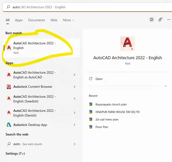
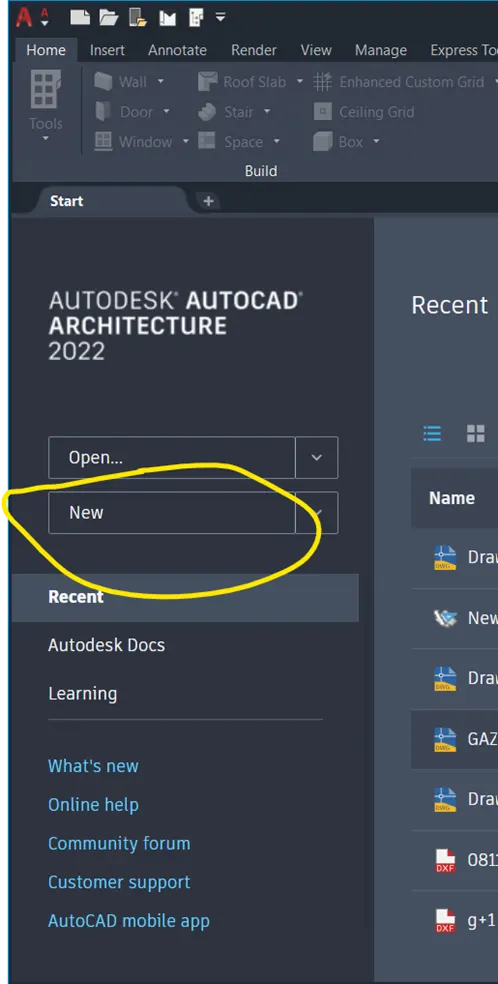
- Click on the Start Drawing icon or New . The AutoCAD window will open.
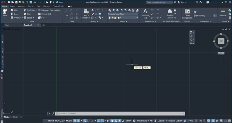
- In the command line, enter startup and then enter the value 1
- Now, go to the application menu and click on the new
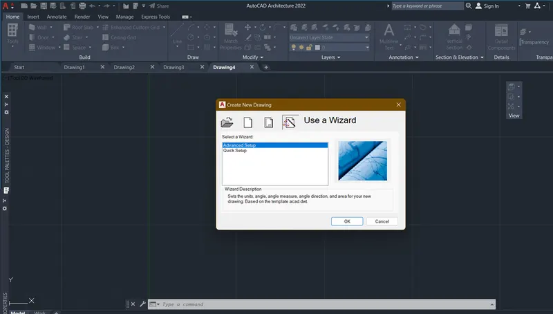
- A dialogue page will appear showing create a new drawing, go to quick setup. As the given draft is in meters, select the Decimal Units.
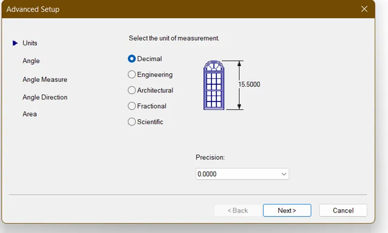
- Now choose the units as engineering and area as 1’ x 9”
- Customize the drafting settings as per the requirements like cross hair size, color and visibility of co- ordinate data.

- Recheck as the units are in meters or cm by entering the units in the command line and change if not changed.
- Turn on the Ortho mode by clicking F8 on keyboard which helps in drawing the straight lines.
- Lets start from the bottom of the draft.
- Invoke rectangle from command line by entering REC
- RECTANG Specify the first corner point as 2,2 ( meters)

- Specify the other corner as @0.9,0.25

- Invoke Polyline from command line by entering PL
- Specify the start point as 2.2 , 2.25 (or) specify the next point by positioning the cursor in the said direction and enter the value ( Direct Coordinate system)
- Specify the next point: position the cursor and enter the distance 0.4
- Specify the next point: position the cursor and enter the distance 0.05
- Specify the next point: position the cursor and enter the distance 0.4
- Specify the next point: position the cursor and enter the distance 0.05
- Specify the next point: position the cursor and enter the distance 1.65 ( plint height + floor thickness+ column extension)
- Specify the next point: position the cursor and enter the distance 0.3 ( column width or dia)
- Specify the next point: position the cursor and enter the distance 1.65 ( plint height + floor thickness+ column extension)
- Specify the next point: position the cursor and enter the distance 0.05
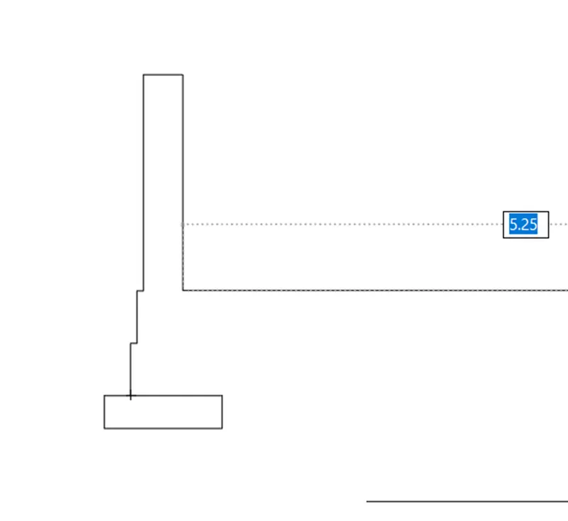
- Specify the next point: position the cursor and enter the distance 0.4
- Specify the next point: position the cursor and enter the distance 0.05
- Specify the next point: position the cursor and enter the distance 0.4 and click escape
- Place the cursor on the footing top and know the coordinates or from there position the next dimension
Ab. Invoke the polyline by entering pl in the command bar.
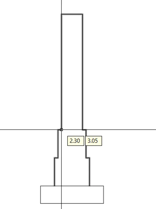
Ac. Specify start point: enter the coordinates as 2.25, 3.05 or place the cursor for the next dimension.
Ad. Specify the next point: position the cursor and enter the distance 1.15
Ae. Specify the next point: position the cursor and enter the distance 0.15
Af. Specify the next point: position the cursor and enter the distance 1.15 and click Esc
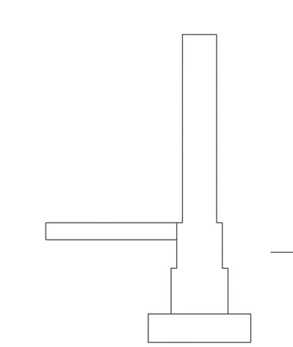
Ag. Specify start point: enter the coordinates as 1.10, 3.05 or place the cursor for the next dimension.
Ah. Specify the next point: position the cursor and enter the distance 0.3
Ai. Specify the next point: position the cursor and enter the distance 0.15
Aj. Specify the next point: position the cursor and enter the distance 0.3
Ak. Specify the next point: position the cursor and enter the distance 0.15
Al. Specify the next point: position the cursor and enter the distance 0.3
Am. Specify the next point: position the cursor and enter the distance 0.15
An. Specify the next point: position the cursor and enter the distance 0.3 and enter the esc
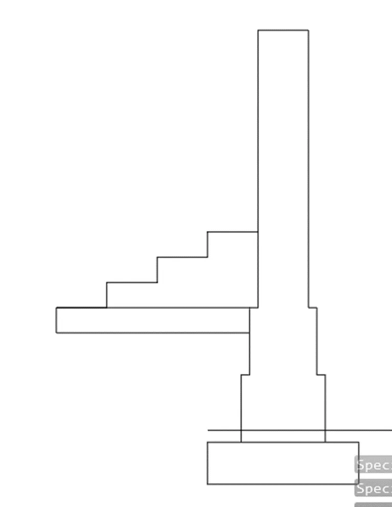
Ao. Invoke the polyline by entering pl in the command bar.
Ap. Specify start point: enter the coordinates as 2.65, 3.05 or place the cursor for the next dimension.
Aq. Specify the next point: position the cursor and enter the distance 1
Ar. Specify the next point: position the cursor and enter the distance 0.6
As. Specify the next point: position the cursor and enter the distance 1.35 ( plinth length+ footing spacing + column dia / width)
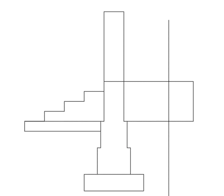
At. Specify the next point: position the cursor and enter the distance 0.05
Au. Specify the next point: position the cursor and enter the distance 0.3
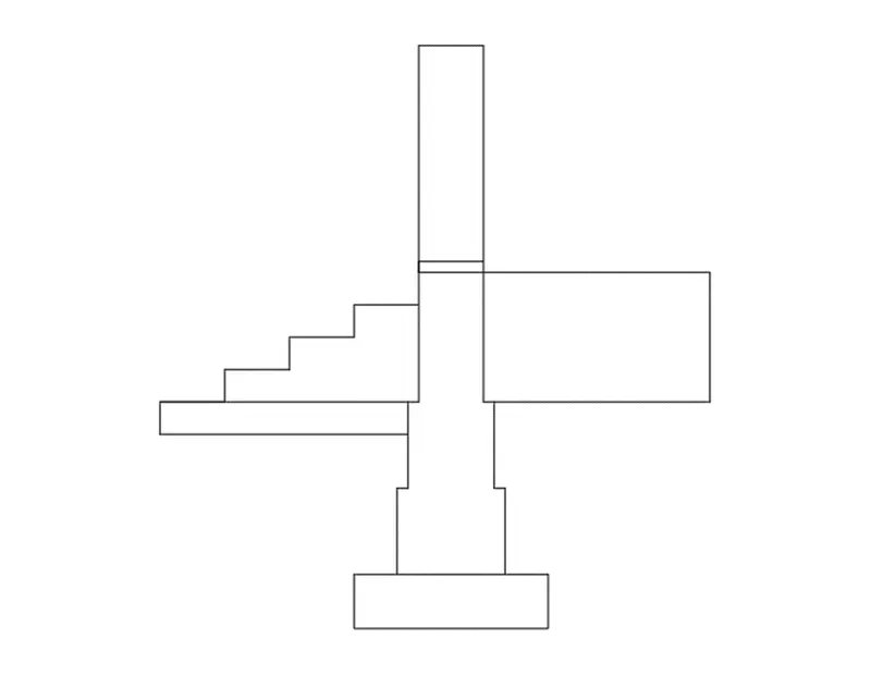
Av. Invoke the dimlinear and mark the dimensions for each and every layer of footing, plinth and steps as shown in the below image.
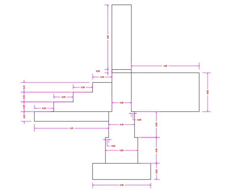
Aw. Invoke the text by entering dt in the command bar and title the drawing.
Result: Hence the result of the above procedure is
2Q. 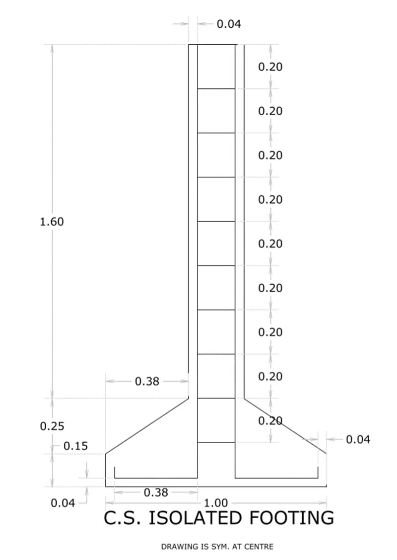
Ans.
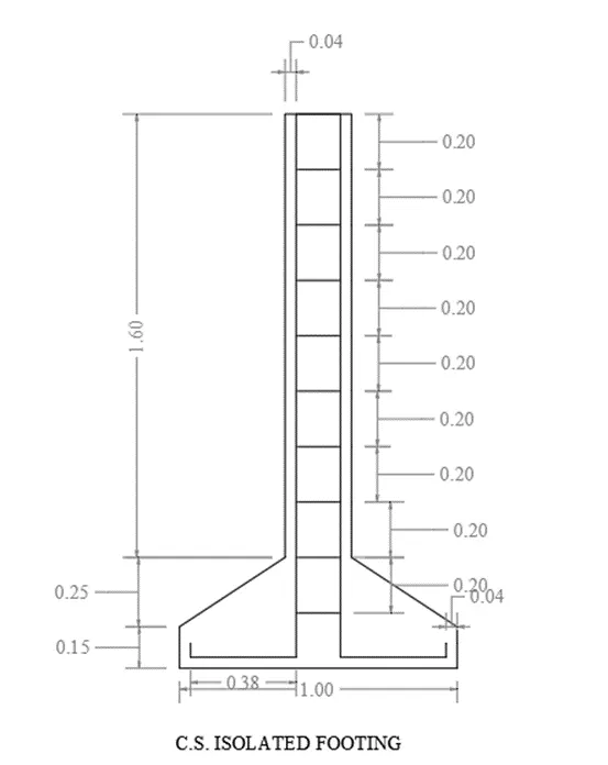
AIM:- To draw the above shown Cross section of load bearing wall over spread footing in AutoCAD
Introduction:- The Isolated footings also known as Pad or Spread footings are commonly used for shallow foundations in order to carry and spread concentrated loads, caused by columns . To draw the above shown drawing in AutoCAD, various tools and commands are used, some of them are Line,Mirror, Offset, Rectangle, Polyline, Erase, Dimlinear, Trim etc., depending on requirment.
Procedure:-
- Open the AutoCAD (above 2017 version)
- Click on the Start Drawing icon or New . The AutoCAD window will open.
- In the command line, enter startup and then enter the value 1
- Now, go to the application menu and click on the new
- A dialogue page will appear showing create a new drawing, go to quick setup. As the given draft is in meters, select the Decimal Units.
- Now choose the units as engineering and area as 1’ x 9”
- Customize the drafting settings as per the requirements like cross hair size, color and visibility of co- ordinate data.
- Recheck as the units are in meters or cm by entering the units in the command line and change if not changed.
- Turn on the Ortho mode by clicking F8 on keyboard which helps in drawing the straight lines.
- Lets start from the bottom of the draft.
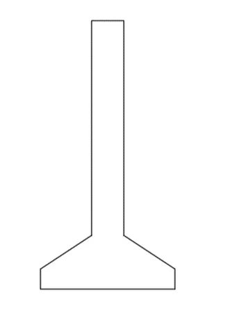
- Invoke the polyline by entering the pl enter or pline.
- Specifiy the start point as 1,1 ( so that we can have enough space for drawing dimension lines and texting)
- Specify the next point: position the cursor and enter the distance 1
- Specify the next point: position the cursor and enter the distance 0.15
- Specify the next point: position the cursor and enter the distance @-0.38,0.25 ( as it is a sloped line, to point out particular next point, I used relative rectangular coordinate system) or else we can use chamfer tool ( which ever is convenient)
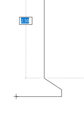
- Specify the next point: position the cursor and enter the distance 1.6
- Specify the next point: position the cursor and enter the distance 0.24
- Specify the next point: position the cursor and enter the distance 1.6
- Specify the next point: position the cursor and enter the distance @-0.38,-0.25 ( as it is a sloped line, to point out particular next point, I used relative rectangular coordinate system)
- Specify the next point: position the cursor and enter the distance 0.15 and click esc
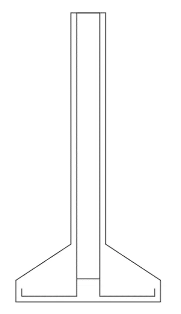
- Invoke the polyline by entering pl or polyline.
- Specify the start point: 1.04,1.09
- Specify the next point: position the cursor and enter the distance @0,-0.05
- Specify the next point: position the cursor and enter the distance 0.38
- Specify the next point: position the cursor and enter the distance 1.96 ( 0.36m in sloped footing and 1.6m in column)
- Specify the next point: position the cursor and enter the distance 0.16
- Specify the next point: position the cursor and enter the distance 1.96
- Specify the next point: position the cursor and enter the distance 0.38
- Specify the next point: position the cursor and enter the distance 0.05 and enter escape
- Now lateral ties are to be drawn.
Ae. Invoke the line by entering L or Line from command prompt.
Af. Specify the start point : 1.42, 1.2
Ag. Specify the next point: position the cursor and enter the distance 0.16
Ah. Now lets invoke the offset tool and make this little easier
Ai. Invoke Offset by entering Of or Offset in command line.
Aj. Specify the first point: position with cursor or enter the coordinates are 1.42, 1.20
Ak. Specify Offset distance : 0.2
Al. Select object to offset : click the line
Am. Click on Multiple

An. Offset the lines till the end.
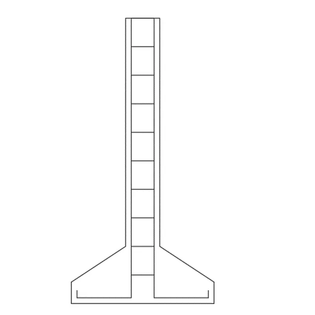
Ao. Invoke the dimlinear by entering diml or dimlinear and draw dimensions for necessary and click esc.
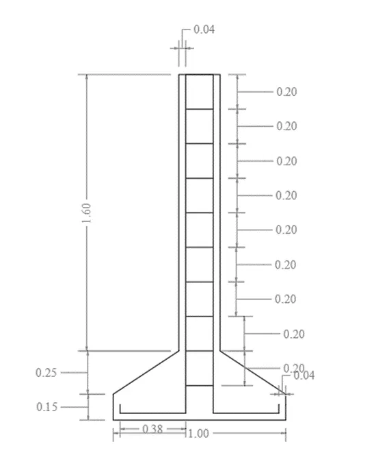
Ap. Invoke the text by entering dt or text and type down the title.
Result: Hence the result of the above procedure is
3Q. 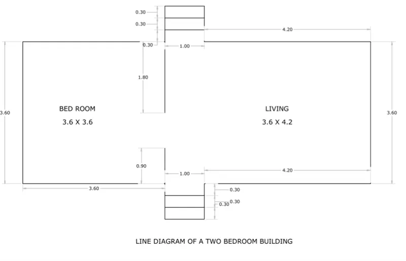
Ans.
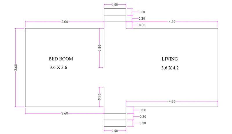
AIM:- To draw the above shown Line Diagraam of a two bedroom building in AutoCAD
Introduction:- The Line diagram means the single centre line plan of the floor without any thickness or width of the structural elements. To draw the above shown drawing in AutoCAD, various tools and commands are used, some of them are Line, Polyline,Offset, Rectangle, Dimlinear, Trim etc.,
Procedure:-
- Open the AutoCAD (above 2017 version)
- Click on the Start Drawing icon or New . The AutoCAD window will open.
- In the command line, enter startup and then enter the value 1
- Now, go to the application menu and click on the new
- A dialogue page will appear showing create a new drawing, go to quick setup. As the given draft is in meters, select the Decimal Units.
- Now choose the units as engineering and area as 1’ x 9”
- Customize the drafting settings as per the requirements like cross hair size, color and visibility of co- ordinate data.
- Recheck as the units are in meters or cm by entering the units in the command line and change if not changed.
- Turn on the Ortho mode by clicking F8 on keyboard which helps in drawing the straight lines.
- Lets start from the bottom of the draft.
- Invoke the line by entering the l enter or line.
- Specifiy the start point as 2,2 ( so that we can have enough space for drawing dimension lines and texting)
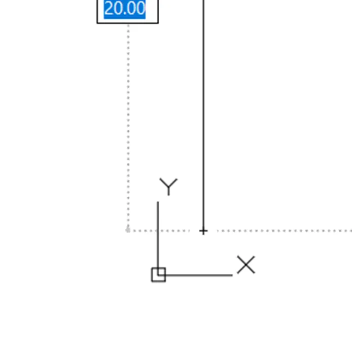
- Specify the next point: position the cursor and enter the distance 3.6 or @3.6<90
- Specify the next point: position the cursor and enter the distance 3.6 or @3.6<0
- Specify the next point: position the cursor and enter the distance 0.9 or @0.9<90
- Specify the next point: position the cursor and enter the distance 1 or @1<0
- Specify the next point: position the cursor and enter the distance 0.9 or @0.9<270
- Specify the next point: position the cursor and enter the distance 4.2 or @4.2<0
- Specify the next point: position the cursor and enter the distance 3.6 or @3.6<270
- Specify the next point: position the cursor and enter the distance 4.2 or @4.2< 180
- Specify the next point: position the cursor and enter the distance 0.9 or @0.9 < 270
- Specify the next point: position the cursor and enter the distance 1 or @1 < 180
- Specify the next point: position the cursor and enter the distance 0.9 or @0.9<90
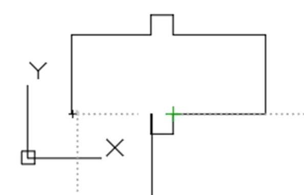
- Specify the next point: position the cursor and enter the distance 3.6 or @3.6<180 or close and esc
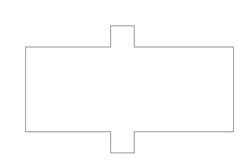
- Now, partition between the Bed room and living room must be drawn.
- Invoke the line, by entering the L or Line in the command line.
- Specify the start point : position the cursor on the wall partition start or enter the coordinates 5.6,2
- Specify the next point : position the cursor and enter the distance as 0.9 or @0.9<90 and esc
- Again Invoke the line by entering the L or Line in the command line.
Ad. Specify the start point: position the cursor or enter the coordinates as 5.6, 5.6
Ae. Specify the next point: position the cursor and enter the length as 1.8 or @1.8<270 and click esc
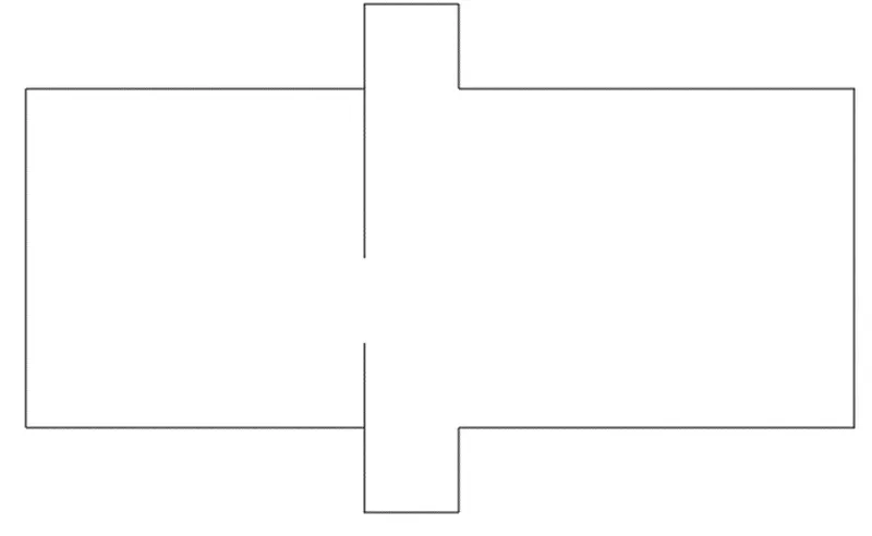
Af. Now give the offset to the steps by invoking the offset by entering the of or offset in command line.
Ag. Specify the distance of the offset : 0.3
Ah. Select the Multiple offset
Ai. Select the object : position the cursor on the object to offset and click till the required as per the plan and click esc.
Aj. Invoke the offset by entering the offset in command line.
Ak. Specify the distance of the offset : 0.3
Al. Select the object : position the cursor on the object to offset and click till the required as per the plan and click esc.
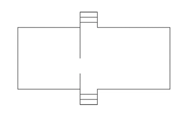
Am. Invoke the dimlinear by entering the diml or dimlinear in command bar.
An. Draw the dimensions as per the plan.
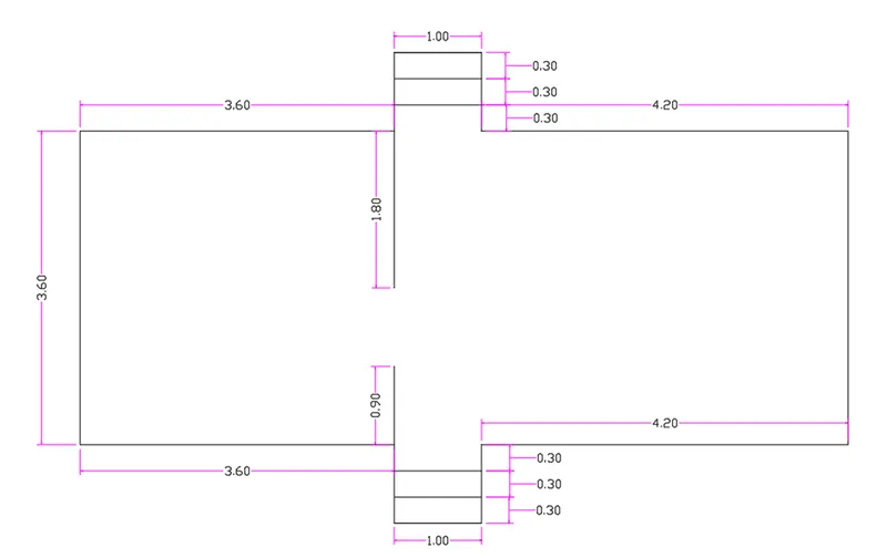
Ao. Invoke the text by entering dt or text in command line.
Ap. Enter the required data and title of the project.
RESULT: The Result of the drawing is below
4Q. 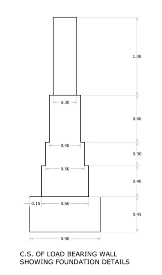
Ans.
AIM:- To draw the above shown cross section of load bearing wall showing foundation details in AutoCAD
Introduction:- The load bearing wall foundation which comes under shallow foundation. It is generally used in low rise or single storied building. To draw the above shown drawing in AutoCAD, various tools and commands are used, some of them are Line, Polyline,Offset, Rectangle, Dimlinear, Trim etc.,
Procedure:-
- Open the AutoCAD (above 2017 version)
- Click on the Start Drawing icon or New . The AutoCAD window will open.
- In the command line, enter startup and then enter the value 1
- Now, go to the application menu and click on the new
- A dialogue page will appear showing create a new drawing, go to quick setup. As the given draft is in meters, select the Decimal Units.
- Now choose the units as engineering and area as 1’ x 9”
- Customize the drafting settings as per the requirements like cross hair size, color and visibility of co- ordinate data.
- Recheck as the units are in meters or cm by entering the units in the command line and change if not changed.
- Turn on the Ortho mode by clicking F8 on keyboard which helps in drawing the straight lines.
- Lets start from the bottom of the draft.
- Invoke the rectangle tool by entering rectangle or rec in command bar,
- Specify the start point : 1,1
- specify the orther corner : 1.9, 1.45

- Click space to invoke the previously used tool ( rectangle)
- Specify the start point or position the cursor at the start point of another rectangle : 1.15,1.45
- specify the other corner : 1.75, 1.85
- Click space to invoke the previously used tool ( rectangle)
- Specify the start point or position the cursor at the start point of another rectangle : 1.20,1.85
- specify the other corner : 1.70, 2.15
- Click space to invoke the previously used tool ( rectangle)
- Specify the start point or position the cursor at the start point of another rectangle : 1.25,2.15
- specify the other corner : 1.65, 2.75
- Click space to invoke the previously used tool ( rectangle)
- Specify the start point or position the cursor at the start point of another rectangle : 1.3,2.75
- Specify the other corner : 1.6, 3.75 and enter esc
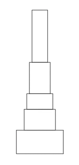
- Invoke the trim command using trim or tr in command line
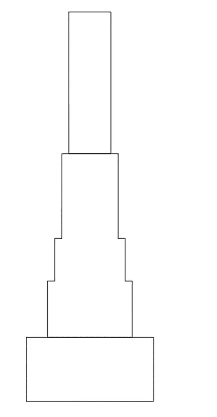
- Select the objects to be trimmed
- Invoke the dimlinear tool by using diml in command line.
- Draw the dimensions as per the above draft.
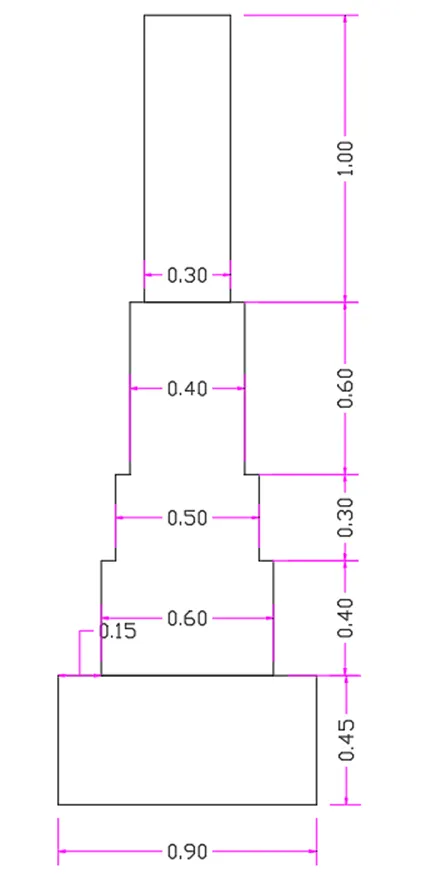
- Invoke the text command by using dt in command line.
- Typedown the Title of the draft.
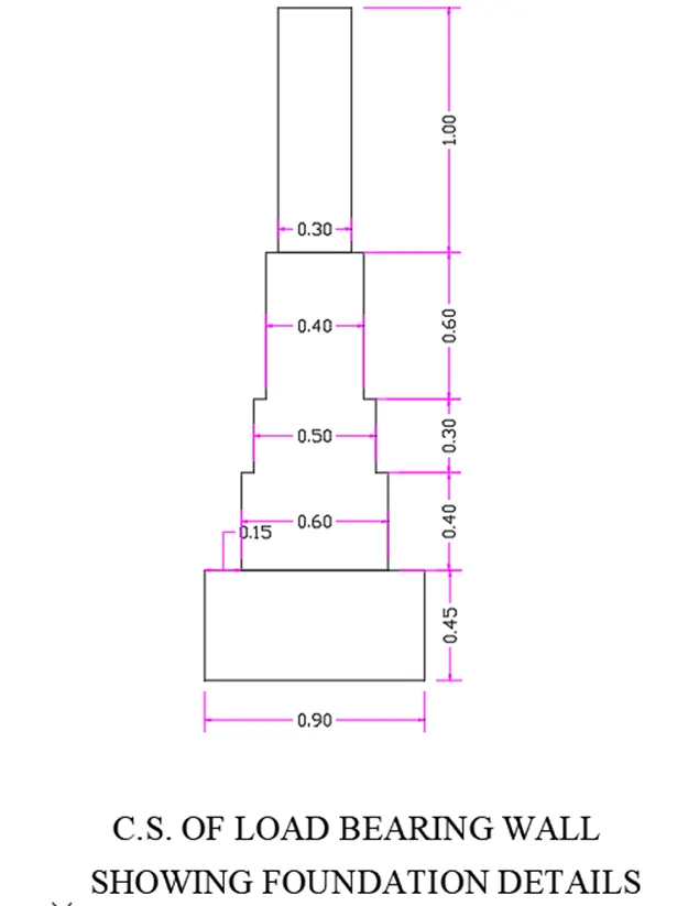
Result: Hence the result is the above drawing.
5Q. 
Ans.
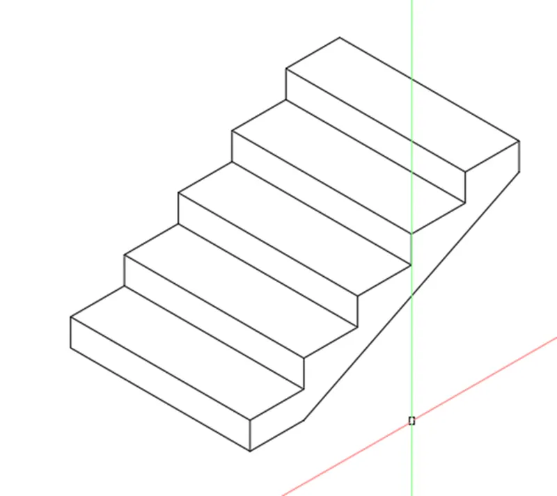
AIM:- To draw the above shown isometric view of the steps in AutoCAD
Introduction:- The Steps used as medium to travel from one floor to other floor. To draw the above shown drawing in AutoCAD, various tools and commands are used, some of them are Line, Polyline,Copy, paste, Offset, Rectangle, Dimlinear, Trim etc.,
Procedure:-
- Open the AutoCAD (above 2017 version)
- Click on the Start Drawing icon or New . The AutoCAD window will open.
- In the command line, enter startup and then enter the value 1
- Now, go to the application menu and click on the new
- A dialogue page will appear showing create a new drawing, go to quick setup. As the given draft is in meters, select the Decimal Units.
- Now choose the units as engineering and area as 1’ x 9”
- Customize the drafting settings as per the requirements like cross hair size, color and visibility of co- ordinate data.
- Recheck as the units are in meters or cm by entering the units in the command line and change if not changed.
- Turn on the Ortho mode by clicking F8 on keyboard which helps in drawing the straight lines.
- Lets change the cursor to draw isometric drawings.
- Invoke the dimension settings by entering the ds or dimension settings in the command line.
- l.Drafting settings window will open on the screen as shown below.
- check or click on radio button beside Isometric snap in Snap type and click ok
- Now the cursor will apear like this
- we can shuffle or change the cursor direction by clicking f5
- lets start the drawing from bottom.
- Invoke the line by entering l or line in the command line.
- specify the start point : 1,1
- specify the next point : or position the cursor in the direction of line to be drawn and enter the distance as 1
- Specify the next point : or position the cursor in the direction of line to be drawn and enter the distance as 0.15
- Specify the next point : or position the cursor in the direction of line to be drawn and enter the distance as 1
- Specify the next point : or position the cursor in the direction of line to be drawn and enter the distance as 0.3
- Specify the next point : or position the cursor in the direction of line to be drawn and enter the distance as 1
- Specify the next point : or position the cursor in the direction of line to be drawn and enter the distance as 0.3 and esc
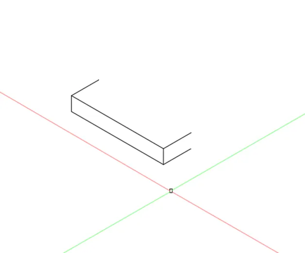
- Invoke the line tool by clicking space bar and position the start point of the line
- Specify the next point : or position the cursor in the direction of line to be drawn and enter the distance as 0.15
- Now select the whole step by window selection or window crossing method and enter co or copy in command line
- Select the base point of the selection : place the cursor as shown below and select the base point
- Now select ARRAY

- Now the steps one over other as per requirement ( another 4) steps as per draft.
Ae. Now Invoke Line tool by entering l or line in command line
Af. Specify the start point: or position the cursor in the direction of line to be drawn and enter the distance as 0.15
Ag. Specify the next point : or position the cursor in the direction of line to be drawn and enter the distance or join the line as per refernce from osnap
Ah. Specify the next point : or position the cursor in the direction of line to be drawn and enter the distance as 0.3 and click esc
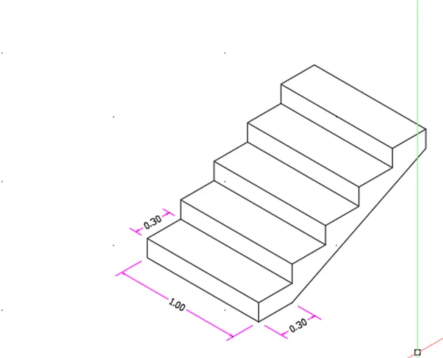
Ai. Invoke the dimlinear tool by entering the diml or dimlinear in the command line and draw the necessary dimensions as per the plan.
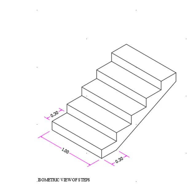
Aj. Invoke the text tool by entering the dt ot text in the command line and enter the title.
RESULT: Hence the result is in below
6Q. 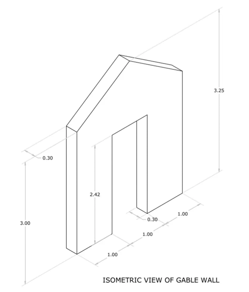
Ans.
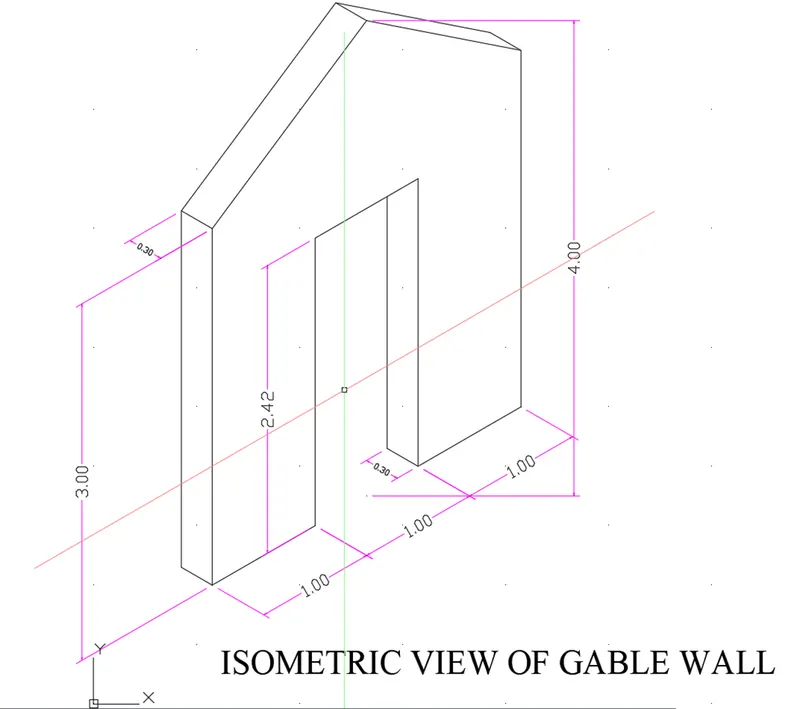
AIM:- To draw the above shown isometric view of the steps in AutoCAD
Introduction:- The Steps used as medium to travel from one floor to other floor. To draw the above shown drawing in AutoCAD, various tools and commands are used, some of them are Line, Polyline,Copy, paste, Offset, Rectangle, Dimlinear, Trim etc.,
Procedure:-
- Open the AutoCAD (above 2017 version)
- Click on the Start Drawing icon or New . The AutoCAD window will open.
- In the command line, enter startup and then enter the value 1
- Now, go to the application menu and click on the new
- A dialogue page will appear showing create a new drawing, go to quick setup. As the given draft is in meters, select the Decimal Units.
- Now choose the units as engineering and area as 1’ x 9”
- Customize the drafting settings as per the requirements like cross hair size, color and visibility of co- ordinate data.
- Recheck as the units are in meters or cm by entering the units in the command line and change if not changed.
- Turn on the Ortho mode by clicking F8 on keyboard which helps in drawing the straight lines.
- Lets change the cursor to draw isometric drawings.
- Invoke the dimension settings by entering the ds or dimension settings in the command line.
l.Drafting settings window will open on the screen as shown below.
- check or click on radio button beside Isometric snap in Snap type and click ok
- Now the cursor will apear like this
- we can shuffle or change the cursor direction by clicking f5
- lets start the drawing from bottom.
- Invoke the line by entering l or line in the command line.
- specify the start point : 1,1
- specify the next point : or position the cursor in the direction of line to be drawn and enter the distance as 1
- specify the next point : or position the cursor in the direction of line to be drawn and enter the distance as 1
- specify the next point : or position the cursor in the direction of line to be drawn and enter the distance as 2.42
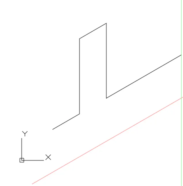
- specify the next point : or position the cursor in the direction of line to be drawn and enter the distance as 1
- Specify the next point : or position the cursor in the direction of line to be drawn and enter the distance as 2.42
- Specify the next point : or position the cursor in the direction of line to be drawn and enter the distance as 1
- Specify the next point : or position the cursor in the direction of line to be drawn and enter the distance as 3
- Specify the next point : or position the cursor in the direction of line to be drawn and enter the distance as 1.5
- Specify the next point : or position the cursor in the direction of line to be drawn and enter the distance as 1 and esc
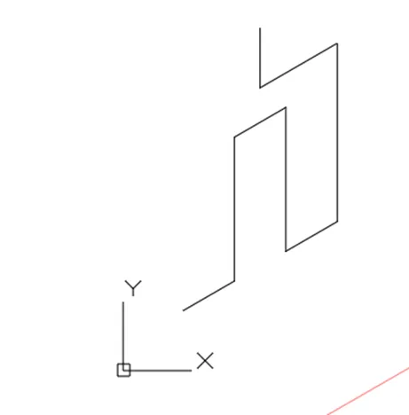
- Invoke the line command by pressing space bar ( Space bar invokes previous tool)
- Specify the start point : 1,1
- specify the next point : or position the cursor in the direction of line to be drawn and enter the distance as 3
- specify the next point : or position the cursor in the direction of line to be drawn and enter the distance or click on the referred point.
Af. specify the next point : or position the cursor in the direction of line to be drawn and enter the distance as 0.3 and esc
Ag. Invoke the line command by pressing space bar ( Space bar invokes previous tool)
Ah. Specify the start point : click on the referred point.
Ai. specify the next point : or position the cursor in the direction of line to be drawn and enter the distance as 0.3
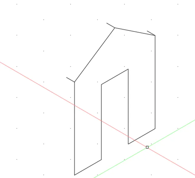
Aj. specify the next point : or position the cursor in the direction of line to be drawn and enter the distance or click on the referred point.
Ak. specify the next point : or position the cursor in the direction of line to be drawn and enter the distance or click on the referred point.
Al. specify the next point : or position the cursor in the direction of line to be drawn and enter the distance as 0.3
Am. Invoke the line command by pressing space bar ( Space bar invokes previous tool)
An. Specify the start point : click on the referred point.
Ao. specify the next point : or position the cursor in the direction of line to be drawn and enter the distance as 3
Ap. specify the next point : or position the cursor in the direction of line to be drawn and enter the distance as 0.3 and esc
Aq. Invoke the line command by pressing space bar ( Space bar invokes previous tool)
Ar. Specify the start point : click on the referred point.
As. specify the next point : or position the cursor in the direction of line to be drawn and enter the distance as 0.3
As. specify the next point : or position the cursor in the direction of line to be drawn and enter the distance or click on the referred point and esc
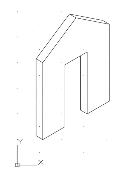
At. Invoke the dimlinear tool by entering the diml or dimlinear in the command line and draw the necessary dimensions as per the plan
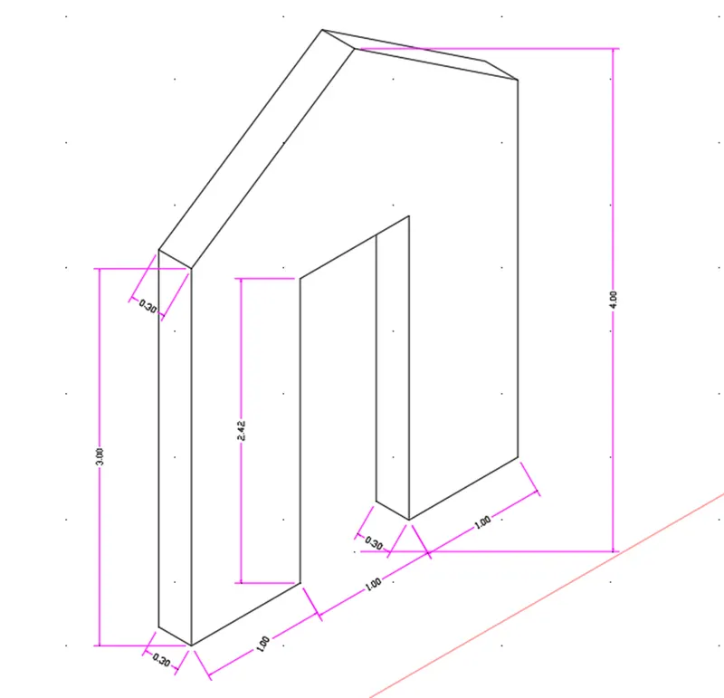
Au. Incase if you need dimensions in isometric, select dimensions inclined in Annotate ribbon and then draw the dimensions and then select the dimensions lines and enter dimedit and select oblique and select the planes to referred dimesions that should be in isometric.
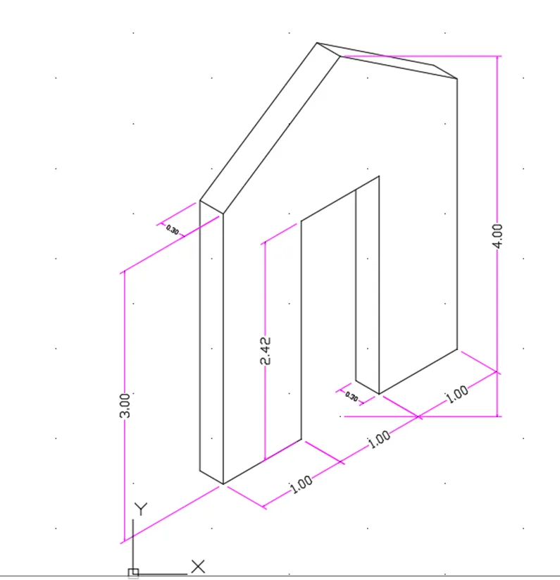
Av. Invoke the text tool by entering the dt ot text in the command line and enter the title.
Result: Hence the result is the below drawing