Creation of geometries by Coordinate system methods using AutoCad
- Create the geometries from P1 to P2 using all the coordinates system methods. You need to use the Line tool to create the geometries. Where required you need to use the circle tool.
Please read the drawings and find out the missing dimensions before working on the sketches.
Note: Use the Imperial Template and the Decimal Units to draft the features. Dimensions are there for
references.
1Ans. 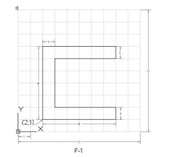
AIM- To create the geometries from P 1 to P10 using all coordinates system methods by using the line tool.
PROCEDURE-
- Open the AutoCAD (above 2017 version)
- Click on the Start Drawing icon. The AutoCAD window will open.
- In the command line, enter startup and then enter the value 1
- Now, go to the application menu and click on the new
- A dialogue page will appear showing create a new drawing, go to quick setup
- Now choose the units as engineering and area as 1’ x 9”
- Customize the drafting settings as per the requirements like cross hair size, color and visibility of co- ordinate data.
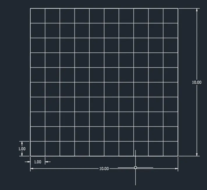
- Create a 10’ x 10’ rectangular box from rectangular tool bar or by line to draw the mentioned figures
Absolute coordinate system:
- Invoke the line tool from command bar by entering l enter or line enter.
- Line- Specify first point: 2, 1
- Specify next point or undo: 2, 7
- Specify next point or undo: 8, 7
- Specify next point or undo: 8, 6
- Specify next point or undo: 3, 6
- Specify next point or undo: 3, 2
- Specify next point or undo: 8, 2
- Specify next point or undo: 8, 1
- Specify next point or close: 2, 1 or close
Relative rectangular coordinate system
- Invoke the line tool from command bar by entering l enter or line enter.
- Line- Specify first point: 2, 1
- Specify next point or undo: @0, 6
- Specify next point or undo: @6, 0
- Specify next point or undo: @0,-1
- Specify next point or undo: @-5, 0
- Specify next point or undo: @0,-4
- Specify next point or undo: @5, 0
- Specify next point or undo: @0,-1
- Specify next point or close: @-6, 0 or close
Relative Polar coordinate system
- Invoke the line tool from command bar by entering l enter or line enter.
- Line- Specify first point: 2, 1
- Specify next point or undo: @6 <90
- Specify next point or undo: @6 < 0
- Specify next point or undo: @1< 270
- Specify next point or undo: @ 5< 180
- Specify next point or undo: @4< 270
- Specify next point or undo: @5<0
- Specify next point or undo: @1<270
- Specify next point or close: @6<180 or close
Direct coordinate system
- Invoke the line tool from command bar by entering l enter or line enter.
- Line- Specify first point: 2, 1
- Specify next point or undo: position the cursor and enter the distance 6
- Specify next point or undo: position the cursor and enter the distance 6
- Specify next point or undo: position the cursor and enter the distance 1
- Specify next point or undo: position the cursor and enter the distance 5
- Specify next point or undo: position the cursor and enter the distance 4
- Specify next point or undo: position the cursor and enter the distance 5
- Specify next point or undo: position the cursor and enter the distance 1
- Specify next point or close: Specify next point or undo: position the cursor and enter the distance 6
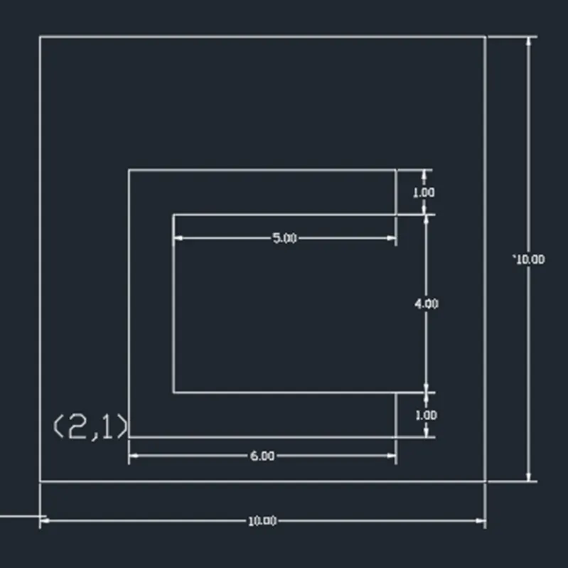
RESULT- Hence the result is
2Ans. 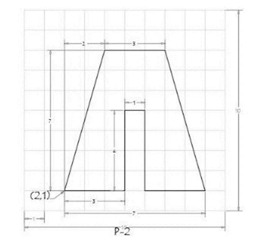
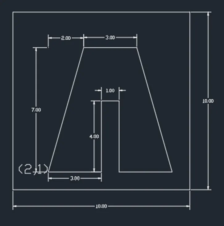
AIM- To create the geometries from P 1 to P10 using all coordinates system methods by using the line tool.
PROCEDURE-
- Open the AutoCAD (above 2017 version)
- Click on the Start Drawing icon. The AutoCAD window will open.
- In the command line, enter startup and then enter the value 1
- Now, go to the application menu and click on the new
- A dialogue page will appear showing create a new drawing, go to quick setup
- Now choose the units as engineering and area as 1’ x 9”
- Customize the drafting settings as per the requirements like cross hair size, color and visibility of co- ordinate data.
- Create a 10’ x 10’ rectangular box from rectangular tool bar or by line to draw the mentioned figures
Absolute coordinate system:
- Invoke the line tool from command bar by entering l enter or line enter.
- Line- Specify first point: 2, 1
- Specify next point or undo: 5, 1
- Specify next point or undo: 5, 5
- Specify next point or undo: 6, 5
- Specify next point or undo: 6, 1
- Specify next point or undo: 9, 1
- Specify next point or undo: 7, 8
- Specify next point or undo: 4, 8
- Specify next point or close: 2, 1 or close
Relative rectangular coordinate system
- Invoke the line tool from command bar by entering l enter or line enter.
- Line- Specify first point: 2, 1
- Specify next point or undo: @3, 0
- Specify next point or undo: @0, 4
- Specify next point or undo: @1, 0
- Specify next point or undo: @0,-4
- Specify next point or undo: @3, 0
- Specify next point or undo: @-2, 7
- Specify next point or undo: @-3, 0
- Specify next point or close: @-2,-7 or close
Relative Polar coordinate system
- Invoke the line tool from command bar by entering l enter or line enter.
- Line- Specify first point: 2, 1
- Specify next point or undo: @3<0
- Specify next point or undo: @4 < 90
- Specify next point or undo: @1< 0
- Specify next point or undo: @ 4< 270
- Specify next point or undo: @3< 0
- Specify next point or undo: @7<106
- Specify next point or undo: @3<180
- Specify next point or close: close
Direct coordinate system
- Invoke the line tool from command bar by entering l enter or line enter.
- Line- Specify first point: 2, 1
- Specify next point or undo: position the cursor and enter the distance 3
- Specify next point or undo: position the cursor and enter the distance 4
- Specify next point or undo: position the cursor and enter the distance 1
- Specify next point or undo: position the cursor and enter the distance 4
- Specify next point or undo: position the cursor and enter the distance 3
- Specify next point or undo: position the cursor and enter the distance 7
- Specify next point or undo: position the cursor and enter the distance 3
- Specify next point or close: Specify next point or undo: position the cursor and enter the distance 7
RESULT- Hence the result is
3Ans. 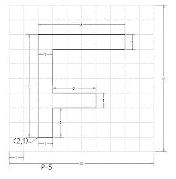
AIM- To create the geometries from P 1 to P10 using all coordinates system methods by using the line tool.
PROCEDURE-
- Open the AutoCAD (above 2017 version)
- Click on the Start Drawing icon. The AutoCAD window will open.
- In the command line, enter startup and then enter the value 1
- Now, go to the application menu and click on the new
- A dialogue page will appear showing create a new drawing, go to quick setup
- Now choose the units as engineering and area as 1’ x 9”
- Customize the drafting settings as per the requirements like cross hair size, color and visibility of co- ordinate data.
- Create a 10’ x 10’ rectangular box from rectangular tool bar or by line to draw the mentioned figures
Absolute coordinate system:
- Invoke the line tool from command bar by entering l enter or line enter.
- Line- Specify first point: 2, 1
- Specify next point or undo: 2, 8
- Specify next point or undo: 8, 8
- Specify next point or undo: 8, 7
- Specify next point or undo: 3, 7
- Specify next point or undo: 3, 4
- Specify next point or undo: 6, 4
- Specify next point or undo: 6, 3
- Specify next point or close: 3, 3
- Specify next point or undo: 3, 1
- Specify next point or undo: 2, 1 or close
Relative rectangular coordinate system
- Invoke the line tool from command bar by entering l enter or line enter.
- Line- Specify first point: 2, 1
- Specify next point or undo: @0, 7
- Specify next point or undo: @6, 0
- Specify next point or undo: @0,-1
- Specify next point or undo: @-5, 0
- Specify next point or undo: @0,-3
- Specify next point or undo: @3, 0
- Specify next point or undo: @0,-1
- Specify next point or close: @-3, 0
- Specify next point or undo: @0,-2
- Specify next point or close: @-1, 0 or close
Relative Polar coordinate system
- Invoke the line tool from command bar by entering l enter or line enter.
- Line- Specify first point: 2, 1
- Specify next point or undo: @7<90
- Specify next point or undo: @6 < 0
- Specify next point or undo: @1< 270
- Specify next point or undo: @ 5 < 180
- Specify next point or undo: @3< 270
- Specify next point or undo: @3<0
- Specify next point or undo: @1<270
- Specify next point or undo: @ 3< 180
- Specify next point or undo: @2< 270
- Specify next point or undo: @1<180 or close
Direct coordinate system
- Invoke the line tool from command bar by entering l enter or line enter.
- Line- Specify first point: 2, 1
- Specify next point or undo: position the cursor and enter the distance 7
- Specify next point or undo: position the cursor and enter the distance 6
- Specify next point or undo: position the cursor and enter the distance 1
- Specify next point or undo: position the cursor and enter the distance 5
- Specify next point or undo: position the cursor and enter the distance 3
- Specify next point or undo: position the cursor and enter the distance 3
- Specify next point or undo: position the cursor and enter the distance 1
- Specify next point or undo: position the cursor and enter the distance 3
- Specify next point or undo: position the cursor and enter the distance 2
- Specify next point or undo: position the cursor and enter the distance 1 or close
RESULT- Hence the result is 
4Ans. 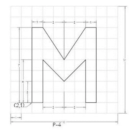
AIM- To create the geometries from P 1 to P10 using all coordinates system methods by using the line tool.
PROCEDURE-
- Open the AutoCAD (above 2017 version)
- Click on the Start Drawing icon. The AutoCAD window will open.
- In the command line, enter startup and then enter the value 1
- Now, go to the application menu and click on the new
- A dialogue page will appear showing create a new drawing, go to quick setup
- Now choose the units as engineering and area as 1’ x 9”
- Customize the drafting settings as per the requirements like cross hair size, color and visibility of co- ordinate data.
- Create a 10’ x 10’ rectangular box from rectangular tool bar or by line to draw the mentioned figures
Absolute coordinate system:
- Invoke the line tool from command bar by entering l enter or line enter.
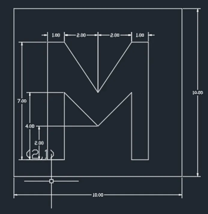
- Line- Specify first point: 2, 1
- Specify next point or undo: 2, 8
- Specify next point or undo: 3, 8
- Specify next point or undo: 5, 5
- Specify next point or undo: 7, 8
- Specify next point or undo: 8, 8
- Specify next point or undo: 8, 1
- Specify next point or undo: 7, 1
- Specify next point or close: 7, 5
- Specify next point or undo: 5, 3
- Specify next point or undo: 3, 5
- Specify next point or undo: 3, 1
- Specify next point or undo: close
Relative rectangular coordinate system
- Invoke the line tool from command bar by entering l enter or line enter.
- Line- Specify first point: 2, 1
- Specify next point or undo: @0, 7
- Specify next point or undo: @1, 0
- Specify next point or undo: @2,-3
- Specify next point or undo: @2, 3
- Specify next point or undo: @1, 0
- Specify next point or undo: @0,-7
- Specify next point or undo: @-1, 0
- Specify next point or close: @0, 4
- Specify next point or undo: @-2,-2
- Specify next point or undo: @-2, 2
- Specify next point or undo: @0,-4
- Specify next point or close: @-1, 0 or close
Relative Polar coordinate system
- Invoke the line tool from command bar by entering l enter or line enter.
- Line- Specify first point: 2, 1
- Specify next point or undo: @7<90
- Specify next point or undo: @1 < 0
- Specify next point or undo: @3.52< 303.7
- Specify next point or undo: @ 3.52 < 56.31
- Specify next point or undo: @1< 0
- Specify next point or undo: @7<270
- Specify next point or undo: @1<180
- Specify next point or undo: @ 4< 90
- Specify next point or undo: @2.82< 225
- Specify next point or undo: @2.82<135
- Specify next point or undo: @4<270
- Specify next point or close: @1<180 or close
Direct coordinate system
- Invoke the line tool from command bar by entering l enter or line enter.
- Line- Specify first point: 2, 1
- Specify next point or undo: position the cursor and enter the distance 7
- Specify next point or undo: position the cursor and enter the distance 1
- Specify next point or undo: position the cursor and enter the distance 3.52
- Specify next point or undo: position the cursor and enter the distance 3.52
- Specify next point or undo: position the cursor and enter the distance 1
- Specify next point or undo: position the cursor and enter the distance 7
- Specify next point or undo: position the cursor and enter the distance 1
- Specify next point or undo: position the cursor and enter the distance 4
- Specify next point or undo: position the cursor and enter the distance 2.82
- Specify next point or undo: position the cursor and enter the distance 2.82
- Specify next point or undo: position the cursor and enter the distance 4
- Specify next point or close: Specify next point or undo: position the cursor and enter the distance 1 or close
RESULT- Hence the result is
5Ans. 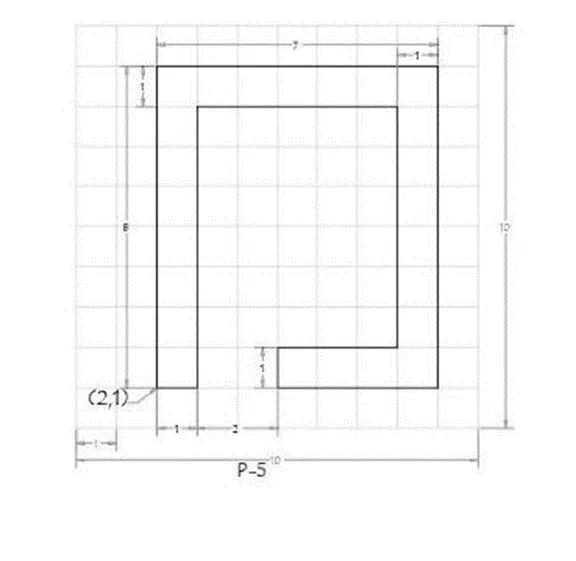
AIM- To create the geometries from P 1 to P10 using all coordinates system methods by using the line tool.
PROCEDURE-
- Open the AutoCAD (above 2017 version)
- Click on the Start Drawing icon. The AutoCAD window will open.
- In the command line, enter startup and then enter the value 1
- Now, go to the application menu and click on the new
- A dialogue page will appear showing create a new drawing, go to quick setup
- Now choose the units as engineering and area as 1’ x 9”
- Customize the drafting settings as per the requirements like cross hair size, color and visibility of co- ordinate data.
- Create a 10’ x 10’ rectangular box from rectangular tool bar or by line to draw the mentioned figures
Absolute coordinate system:
- Invoke the line tool from command bar by entering l enter or line enter.
- Line- Specify first point: 2, 1
- Specify next point or undo: 2, 9
- Specify next point or undo: 9, 9
- Specify next point or undo: 9, 1
- Specify next point or undo: 5, 1
- Specify next point or undo: 5, 2
- Specify next point or undo: 8, 2
- Specify next point or undo: 8, 8
- Specify next point or undo: 3, 8
- Specify next point or undo: 3, 1
- Specify next point or close: 2, 1 or close
Relative rectangular coordinate system
- Invoke the line tool from command bar by entering l enter or line enter.
- Line- Specify first point: 2, 1
- Specify next point or undo: @0, 8
- Specify next point or undo: @7, 0
- Specify next point or undo: @0,-8
- Specify next point or undo: @-4, 0
- Specify next point or undo: @0, 1
- Specify next point or undo: @3, 0
- Specify next point or undo: @0, 6
- Specify next point or close: @-5, 0
- Specify next point or undo: @0,-7
- Specify next point or close: @-1, 0 or close
Relative Polar coordinate system
- Invoke the line tool from command bar by entering l enter or line enter.
- Line- Specify first point: 2, 1
- Specify next point or undo: @8<90
- Specify next point or undo: @7 < 0
- Specify next point or undo: @8< 270
- Specify next point or undo: @ 4< 180
- Specify next point or undo: @1< 90
- Specify next point or undo: @3<0
- Specify next point or undo: @6<90
- Specify next point or undo: @5<180
- Specify next point or close: @7<270
- Specify next point or undo: @1<180 or close
Direct coordinate system
- Invoke the line tool from command bar by entering l enter or line enter.
- Line- Specify first point: 2, 1
- Specify next point or undo: position the cursor and enter the distance 8
- Specify next point or undo: position the cursor and enter the distance 7
- Specify next point or undo: position the cursor and enter the distance 8
- Specify next point or undo: position the cursor and enter the distance 4
- Specify next point or undo: position the cursor and enter the distance 1
- Specify next point or undo: position the cursor and enter the distance 3
- Specify next point or undo: position the cursor and enter the distance 6
- Specify next point or undo: position the cursor and enter the distance 5
- Specify next point or undo: position the cursor and enter the distance 7
- Specify next point or close: Specify next point or undo: position the cursor and enter the distance -1 or close
RESULT- Hence the result is 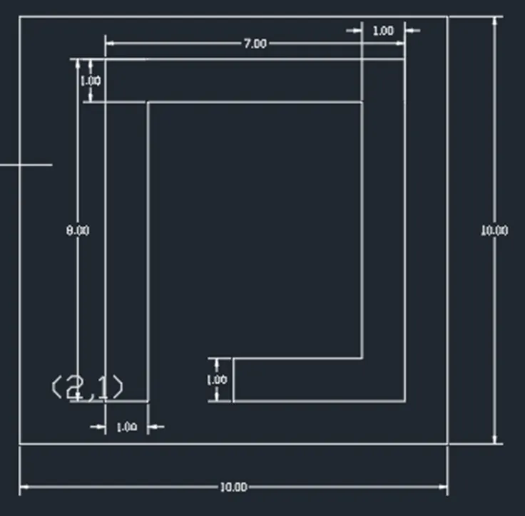
6Ans. 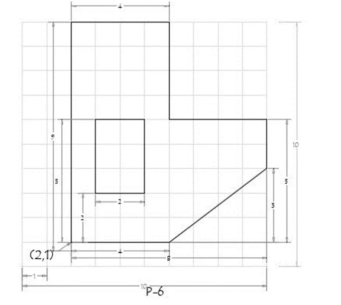
AIM- To create the geometries from P 1 to P10 using all coordinates system methods by using the line tool.
PROCEDURE-
- Open the AutoCAD (above 2017 version)
- Click on the Start Drawing icon. The AutoCAD window will open.
- In the command line, enter startup and then enter the value 1
- Now, go to the application menu and click on the new
- A dialogue page will appear showing create a new drawing, go to quick setup
- Now choose the units as engineering and area as 1’ x 9”
- Customize the drafting settings as per the requirements like cross hair size, color and visibility of co- ordinate data.
- Create a 10’ x 10’ rectangular box from rectangular tool bar or by line to draw the mentioned figures
Absolute coordinate system:
- Invoke the line tool from command bar by entering l enter or line enter.
- Line- Specify first point: 2, 1
- Specify next point or undo: 2, 10
- Specify next point or undo: 6, 10
- Specify next point or undo: 6, 6
- Specify next point or undo: 10, 6
- Specify next point or undo: 10, 4
- Specify next point or undo: 6, 1
- Specify next point or undo: 2, 1 or close
- Invoke the line tool from command bar by entering L enter or line enter
- Line specify first point: 3, 3
- Specify next point or undo: 5, 3
- Specify next point or undo: 5, 6
- Specify next point or undo: 3, 6
- Specify next point or undo: 3, 3 or close
Relative rectangular coordinate system
- Invoke the line tool from command bar by entering l enter or line enter.
- Line- Specify first point: 2, 1
- Specify next point or undo: @0, 9
- Specify next point or undo: @4, 0
- Specify next point or undo: @0,-4
- Specify next point or undo: @4, 0
- Specify next point or undo: @0,-2
- Specify next point or undo: @-4,-3
- Specify next point or undo: @-4, 0 or close
- Invoke the line tool from command bar by entering l enter or line enter.
- Line- Specify first point: 3, 3
- Specify next point or undo: @2, 0
- Specify next point or undo: @0, 3
- Specify next point or undo: @-2, 0
- Specify next point or close: @0,-3 or close
Relative Polar coordinate system
- Invoke the line tool from command bar by entering L enter or line enter.
- Line- Specify first point: 2, 1
- Specify next point or undo: @9 <90
- Specify next point or undo: @4 < 0
- Specify next point or undo: @4< 270
- Specify next point or undo: @ 4 < 0
- Specify next point or undo: @2 < 270
- Specify next point or undo: @5<217
- Specify next point or undo: @4<180 or close
- Invoke the line tool from command bar by entering l enter or line enter.
- Line- Specify first point: 3, 3
- Specify next point or undo: @ 2< 0
- Specify next point or undo: @3< 90
- Specify next point or undo: @2<180
- Specify next point or undo: @3 <270 or close
Direct coordinate system
- Invoke the line tool from command bar by entering l enter or line enter.
- Line- Specify first point: 2, 1
- Specify next point or undo: position the cursor and enter the distance 9
- Specify next point or undo: position the cursor and enter the distance 4
- Specify next point or undo: position the cursor and enter the distance 4
- Specify next point or undo: position the cursor and enter the distance 4
- Specify next point or undo: position the cursor and enter the distance 2
- Specify next point or undo: position the cursor and enter the distance 4.
- Specify next point or undo: position the cursor and enter the distance 4
- Invoke the line tool from command bar by entering l enter or line enter.
- Line- Specify first point: 3, 3
- Specify next point or undo: position the cursor and enter the distance 2
- Specify next point or undo: position the cursor and enter the distance 3
- Specify next point or undo: position the cursor and enter the distance 2
- Specify next point or undo: position the cursor and enter the distance 3 or close
RESULT- Hence the result is 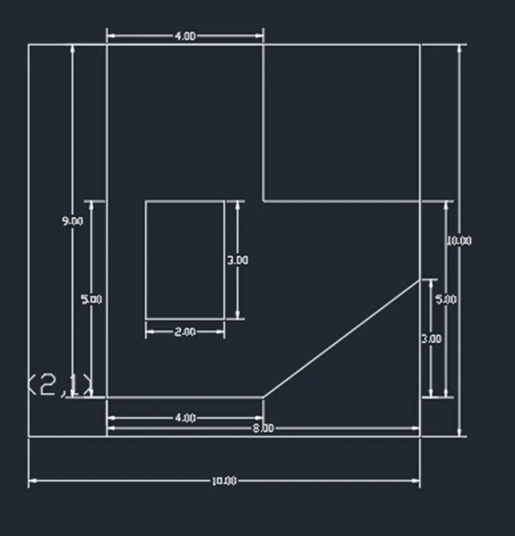
7Ans. 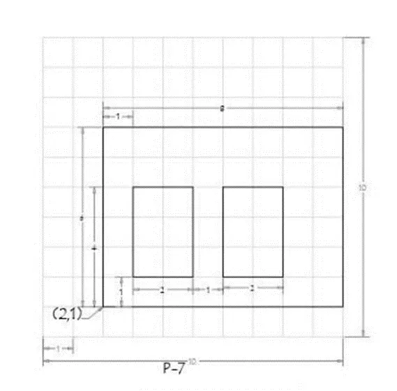
AIM- To create the geometries from P 1 to P10 using all coordinates system methods by using the line tool.
PROCEDURE-
- Open the AutoCAD (above 2017 version)
- Click on the Start Drawing icon. The AutoCAD window will open.
- In the command line, enter startup and then enter the value 1
- Now, go to the application menu and click on the new
- A dialogue page will appear showing create a new drawing, go to quick setup
- Now choose the units as engineering and area as 1’ x 9”
- Customize the drafting settings as per the requirements like cross hair size, color and visibility of co- ordinate data.
- Create a 10’ x 10’ rectangular box from rectangular tool bar or by line to draw the mentioned figures
Absolute coordinate system:
- Invoke the line tool from command bar by entering l enter or line enter.
- Line- Specify first point: 2, 1
- Specify next point or undo: 2, 7
- Specify next point or undo: 10, 7
- Specify next point or undo: 10, 1
- Specify next point or undo: 2, 1 or close
- Invoke the line tool from command bar by entering L enter or line enter
- Line specify first point: 3, 2
- Specify next point or undo: 5, 2
- Specify next point or undo: 5, 5
- Specify next point or undo: 3, 5
- Specify next point or undo: 3, 2 or close
- Invoke the line tool from command bar by entering L enter or line enter
- Line specify first point: 6, 2
- Specify next point or undo: 8, 2
- Specify next point or undo: 8, 5
- Specify next point or undo: 6, 5
- Specify next point or undo: 6, 2 or close
Relative rectangular coordinate system
- Invoke the line tool from command bar by entering l enter or line enter.
- Line- Specify first point: 2, 1
- Specify next point or undo: @0, 6
- Specify next point or undo: @8, 0
- Specify next point or undo: @0,-6
- Specify next point or undo: @-8, 0 or close
- Invoke the line tool from command bar by entering l enter or line enter.
- Line- Specify first point: 3, 2
- Specify next point or undo: @2, 0
- Specify next point or undo: @0, 3
- Specify next point or undo: @-2, 0
- Specify next point or undo: @0,-3 or close
- Invoke the line tool from command bar by entering l enter or line enter.
- Line- Specify first point: 6, 2
- Specify next point or undo: @2, 0
- Specify next point or undo: @0, 3
- Specify next point or undo: @-2, 0
- Specify next point or undo: @0,-3 or close
Relative Polar coordinate system
- Invoke the line tool from command bar by entering L enter or line enter.
- Line- Specify first point: 2, 1
- Specify next point or undo: @6 <90
- Specify next point or undo: @8 < 0
- Specify next point or undo: @6< 270
- Specify next point or undo: @ 8< 180 or close
- Invoke the line tool from command bar by entering l enter or line enter.
- Line- Specify first point: 3, 2
- Specify next point or undo: @ 2< 0
- Specify next point or undo: @3< 90
- Specify next point or undo: @2<180
- Specify next point or undo: @3 <270 or close
- Invoke the line tool from command bar by entering l enter or line enter.
- Line- Specify first point: 6, 2
- Specify next point or undo: @ 2< 0
- Specify next point or undo: @3< 90
- Specify next point or undo: @2<180
- Specify next point or undo: @3 <270 or close
Direct coordinate system
- Invoke the line tool from command bar by entering l enter or line enter.
- Line- Specify first point: 2, 1
- Specify next point or undo: position the cursor and enter the distance 6
- Specify next point or undo: position the cursor and enter the distance 8
- Specify next point or undo: position the cursor and enter the distance 6
- Specify next point or undo: position the cursor and enter the distance 8 or close
- Invoke the line tool from command bar by entering l enter or line enter.
- Line- Specify first point: 3, 2
- Specify next point or undo: position the cursor and enter the distance 2
- Specify next point or undo: position the cursor and enter the distance 3.
- Specify next point or undo: position the cursor and enter the distance 2
- Specify next point or undo: position the cursor and enter the distance 3 or close
- Invoke the line tool from command bar by entering l enter or line enter.
- Line- Specify first point: 6, 2
- Specify next point or undo: position the cursor and enter the distance 2
- Specify next point or undo: position the cursor and enter the distance 3
- Specify next point or undo: position the cursor and enter the distance 2
- Specify next point or undo: position the cursor and enter the distance 3 or close
RESULT- Hence the result is
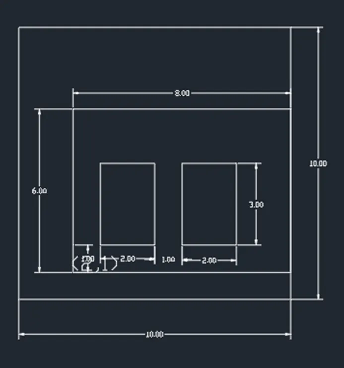
8Ans. 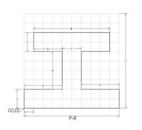
AIM- To create the geometries from P 1 to P10 using all coordinates system methods by using the line tool.
PROCEDURE-
- Open the AutoCAD (above 2017 version)
- Click on the Start Drawing icon. The AutoCAD window will open.
- In the command line, enter startup and then enter the value 1
- Now, go to the application menu and click on the new
- A dialogue page will appear showing create a new drawing, go to quick setup
- Now choose the units as engineering and area as 1’ x 9”
- Customize the drafting settings as per the requirements like cross hair size, color and visibility of co- ordinate data.
- Create a 10’ x 10’ rectangular box from rectangular tool bar or by line to draw the mentioned figures
Absolute coordinate system:
- Invoke the line tool from command bar by entering l enter or line enter.
- Line- Specify first point: 0, 0
- Specify next point or undo: 0, 2
- Specify next point or undo: 4, 2
- Specify next point or undo: 4, 6
- Specify next point or undo: 1, 6
- Specify next point or undo: 1, 8
- Specify next point or undo: 9, 8
- Specify next point or undo: 9, 6
- Specify next point or undo: 6, 6
- Specify next point or undo: 6, 2
- Specify next point or undo: 10, 2
- Specify next point or undo: 10, 0
- Specify next point or undo: 0, 0 or close
Relative rectangular coordinate system
- Invoke the line tool from command bar by entering l enter or line enter.
- Line- Specify first point: 0, 0
- Specify next point or undo: @0, 2
- Specify next point or undo: @4, 0
- Specify next point or undo: @0, 4
- Specify next point or undo: @-3, 0
- Specify next point or undo: @0, 2
- Specify next point or undo: @8, 0
- Specify next point or undo: @0,-2
- Specify next point or close: @-3, 0
- Specify next point or undo: @0,-4
- Specify next point or undo: @4, 0
- Specify next point or close: @0,-2
- Specify next point or undo: @-10, 0 or close
Relative Polar coordinate system
- Invoke the line tool from command bar by entering l enter or line enter.
- Line- Specify first point: 0, 0
- Specify next point or undo: @2<90
- Specify next point or undo: @4 < 0
- Specify next point or undo: @4< 90
- Specify next point or undo: @ 3< 180
- Specify next point or undo: @2< 90
- Specify next point or undo: @8<0
- Specify next point or undo: @2<270
- Specify next point or undo: @3<180
- Specify next point or close: @4<270
- Specify next point or undo: @4<0
- Specify next point or close: @2<270
- Specify next point or undo: @10<180 or close
Direct coordinate system
- Invoke the line tool from command bar by entering l enter or line enter.
- Line- Specify first point: 0, 0
- Specify next point or undo: position the cursor and enter the distance 2
- Specify next point or undo: position the cursor and enter the distance 4
- Specify next point or undo: position the cursor and enter the distance 4
- Specify next point or undo: position the cursor and enter the distance 3
- Specify next point or undo: position the cursor and enter the distance 2
- Specify next point or undo: position the cursor and enter the distance 8
- Specify next point or undo: position the cursor and enter the distance 2
- Specify next point or undo: position the cursor and enter the distance 3
- Specify next point or undo: position the cursor and enter the distance 4
- Specify next point or undo: position the cursor and enter the distance 4
- Specify next point or undo: position the cursor and enter the distance 2
- Specify next point or undo: position the cursor and enter the distance 10 or close
RESULT- Hence the result is
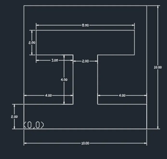
9Ans.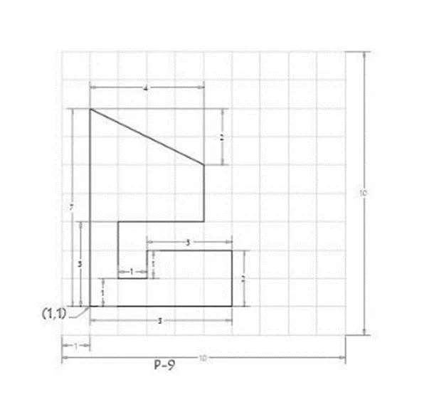
AIM- To create the geometries from P 1 to P10 using all coordinates system methods by using the line tool.
PROCEDURE-
- Open the AutoCAD (above 2017 version)
- Click on the Start Drawing icon. The AutoCAD window will open.
- In the command line, enter startup and then enter the value 1
- Now, go to the application menu and click on the new
- A dialogue page will appear showing create a new drawing, go to quick setup
- Now choose the units as engineering and area as 1’ x 9”
- Customize the drafting settings as per the requirements like cross hair size, color and visibility of co- ordinate data.
- Create a 10’ x 10’ rectangular box from rectangular tool bar or by line to draw the mentioned figures
Absolute coordinate system:
- Invoke the line tool from command bar by entering l enter or line enter.
- Line- Specify first point: 1, 1
- Specify next point or undo: 1, 8
- Specify next point or undo: 5, 6
- Specify next point or undo: 5, 4
- Specify next point or undo: 2, 4
- Specify next point or undo: 2, 2
- Specify next point or undo: 3, 2
- Specify next point or undo: 3, 3
- Specify next point or undo: 6, 3
- Specify next point or undo: 6, 1
- Specify next point or undo: 1, 1 or close
Relative rectangular coordinate system
- Invoke the line tool from command bar by entering l enter or line enter.
- Line- Specify first point: 1, 1
- Specify next point or undo: @0, 7
- Specify next point or undo: @4,-2
- Specify next point or undo: @0,-2
- Specify next point or undo: @-3, 0
- Specify next point or undo: @0,-2
- Specify next point or undo: @1, 0
- Specify next point or undo: @0, 1
- Specify next point or close: @3, 0
- Specify next point or undo: @0,-2
- Specify next point or undo: @-5, 0 or close
Relative Polar coordinate system
- Invoke the line tool from command bar by entering l enter or line enter.
- Line- Specify first point: 1, 1
- Specify next point or undo: @7<90
- Specify next point or undo: @4.5 < 333.43
- Specify next point or undo: @2< 270
- Specify next point or undo: @ 3< 180
- Specify next point or undo: @2< 270
- Specify next point or undo: @1<0
- Specify next point or undo: @1<90
- Specify next point or undo: @3<0
- Specify next point or close: @2<270
- Specify next point or undo: @5<180 or close
Direct coordinate system
- Invoke the line tool from command bar by entering l enter or line enter.
- Line- Specify first point: 1, 1
- Specify next point or undo: position the cursor and enter the distance 7
- Specify next point or undo: position the cursor and enter the distance 4.5
- Specify next point or undo: position the cursor and enter the distance 2
- Specify next point or undo: position the cursor and enter the distance 3
- Specify next point or undo: position the cursor and enter the distance 2
- Specify next point or undo: position the cursor and enter the distance 1
- Specify next point or undo: position the cursor and enter the distance 1
- Specify next point or undo: position the cursor and enter the distance 3
- Specify next point or undo: position the cursor and enter the distance 2
- Specify next point or undo: position the cursor and enter the distance 5 or close
RESULT- Hence the result is
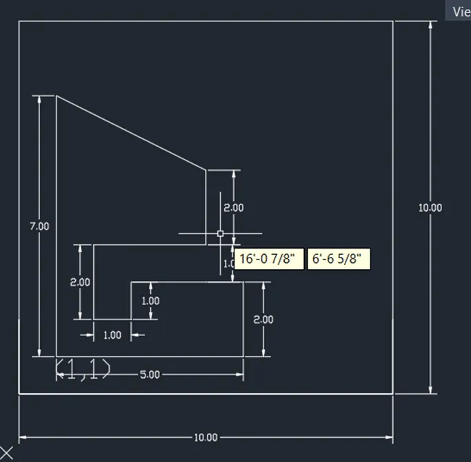
10Ans. 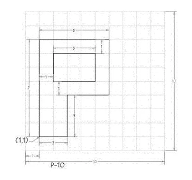
AIM- To create the geometries from P 1 to P10 using all coordinates system methods by using the line tool.
PROCEDURE-
- Open the AutoCAD (above 2017 version)
- Click on the Start Drawing icon. The AutoCAD window will open.
- In the command line, enter startup and then enter the value 1
- Now, go to the application menu and click on the new
- A dialogue page will appear showing create a new drawing, go to quick setup
- Now choose the units as engineering and area as 1’ x 9”
- Customize the drafting settings as per the requirements like cross hair size, color and visibility of co- ordinate data.
- Create a 10’ x 10’ rectangular box from rectangular tool bar or by line to draw the mentioned figures
Absolute coordinate system:
- Invoke the line tool from command bar by entering l enter or line enter.
- Line- Specify first point: 1, 1
- Specify next point or undo: 1, 8
- Specify next point or undo: 6, 8
- Specify next point or undo: 6, 4
- Specify next point or undo: 3, 4
- Specify next point or undo: 3, 1
- Specify next point or undo: 1, 1 or close
- Invoke the line tool from command bar by entering L enter or line enter
- Line specify first point: 2, 5
- Specify next point or undo: 5, 5
- Specify next point or undo: 5, 7
- Specify next point or undo: 2, 7
- Specify next point or undo: 2, 5 or close
Relative rectangular coordinate system
- Invoke the line tool from command bar by entering l enter or line enter.
- Line- Specify first point: 1, 1
- Specify next point or undo: @0, 7
- Specify next point or undo: @5, 0
- Specify next point or undo: @0,-4
- Specify next point or undo: @-3, 0
- Specify next point or undo: @0,-3
- Specify next point or undo: @-2, 0 or close
- Invoke the line tool from command bar by entering l enter or line enter.
- Line- Specify first point: 2, 5
- Specify next point or undo: @3, 0
- Specify next point or undo: @0, 2
- Specify next point or undo: @-3, 0
- Specify next point or close: @0,-2 or close
Relative Polar coordinate system
- Invoke the line tool from command bar by entering L enter or line enter.
- Line- Specify first point: 1, 1
- Specify next point or undo: @7 <90
- Specify next point or undo: @5 < 0
- Specify next point or undo: @4< 270
- Specify next point or undo: @ 3 < 180
- Specify next point or undo: @3 < 270
- Specify next point or undo: @2<180 or close
- Invoke the line tool from command bar by entering l enter or line enter.
- Line- Specify first point: 2, 5
- Specify next point or undo: @ 3< 0
- Specify next point or undo: @2< 90
- Specify next point or undo: @3<180
- Specify next point or undo: @2 <270 or close
Direct coordinate system
- Invoke the line tool from command bar by entering l enter or line enter.
- Line- Specify first point: 1, 1
- Specify next point or undo: position the cursor and enter the distance 7
- Specify next point or undo: position the cursor and enter the distance 5
- Specify next point or undo: position the cursor and enter the distance 4
- Specify next point or undo: position the cursor and enter the distance 3
- Specify next point or undo: position the cursor and enter the distance 3
- Specify next point or undo: position the cursor and enter the distance 2 or close
- Invoke the line tool from command bar by entering l enter or line enter.
- Line- Specify first point: 2, 5
- Specify next point or undo: position the cursor and enter the distance 3
- Specify next point or undo: position the cursor and enter the distance 2
- Specify next point or undo: position the cursor and enter the distance 3
- Specify next point or undo: position the cursor and enter the distance 2 or close
RESULT- Hence the result is
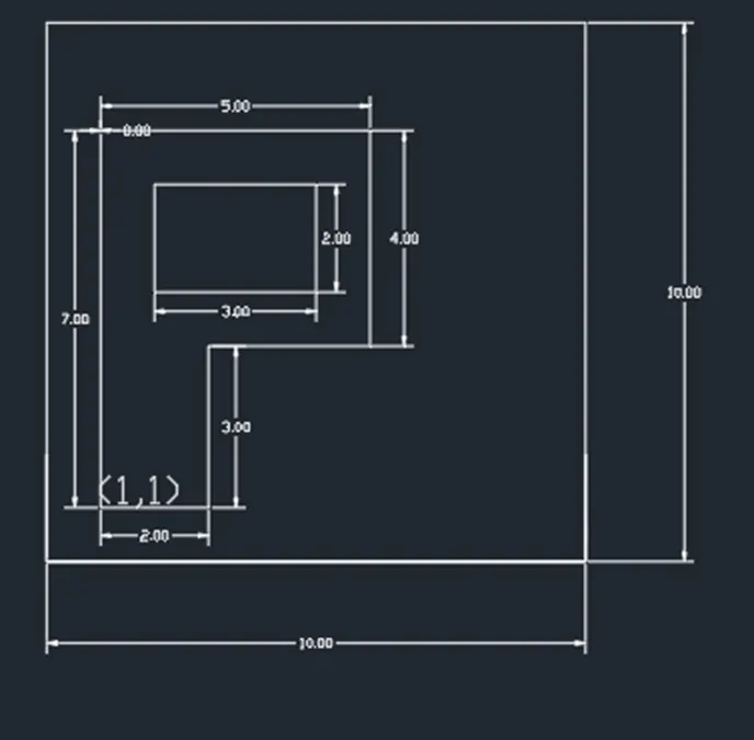
Civil Related Problems
11. Draw the profile and the trusses using any coordinate system methods. The dimensions are there for references.
11Ans. 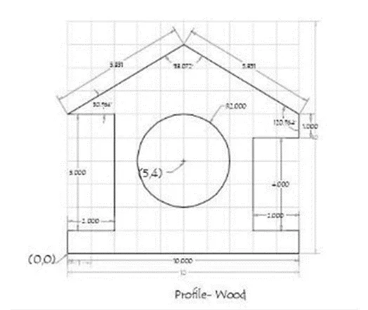
AIM- To draw the profile and the trusses using any coordinate system methods.
PROCEDURE-
- Open the AutoCAD (above 2017 version)
- Click on the Start Drawing icon. The AutoCAD window will open.
- In the command line, enter startup and then enter the value 1
- Now, go to the application menu and click on the new
- A dialogue page will appear showing create a new drawing, go to quick setup
- Now choose the units as engineering and area as 1’ x 9”
- Customize the drafting settings as per the requirements like cross hair size, color and visibility of co- ordinate data.
- Create a 10’ x 10’ rectangular box from rectangular tool bar or by line to draw the mentioned figures
Relative Polar coordinate system
- Invoke the line tool from command bar by entering L enter or line enter.
- Line- Specify first point: 0, 0
- Specify next point or undo: @1 <90
- Specify next point or undo: @2 < 0
- Specify next point or undo: @5< 90
- Specify next point or undo: @ 2 < 180
- Specify next point or undo: @5.831 < 30.964
- Specify next point or undo: @5.831 < 329.036
- Specify next point or undo: @1 < 270
- Specify next point or undo: @2< 180
- Specify next point or undo: @ 4 < 270
- Specify next point or undo: @2 < 0
- Specify next point or undo: @10 < 180 or close
- Invoke the line tool from command bar by entering C enter or circle enter.
- Circle- Specify first point: 5, 4
- Specify radius: 2
RESULT- Hence the result is
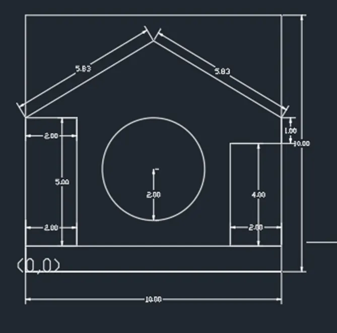
12Ans. 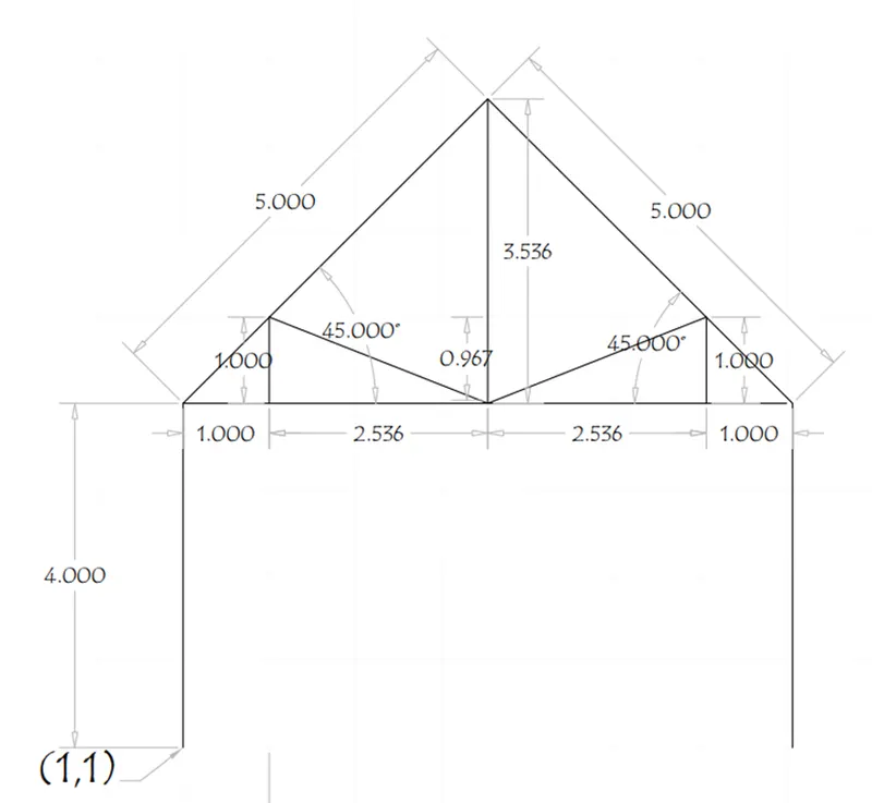
AIM- To draw the profile and the trusses using any coordinate system methods.
PROCEDURE-
- Open the AutoCAD (above 2017 version)
- Click on the Start Drawing icon. The AutoCAD window will open.
- In the command line, enter startup and then enter the value 1
- Now, go to the application menu and click on the new
- A dialogue page will appear showing create a new drawing, go to quick setup
- Now choose the units as engineering and area as 1’ x 9”
- Customize the drafting settings as per the requirements like cross hair size, color and visibility of co- ordinate data.
- Create a 10’ x 10’ rectangular box from rectangular tool bar or by line to draw the mentioned figures
Relative Polar coordinate system
- Invoke the line tool from command bar by entering L enter or line enter.
- Line- Specify first point: 1, 1
- Specify next point or undo: @4 <90
- Specify next point or undo: @5 < 45
- Specify next point or undo: @5< 315
- Specify next point or undo: @ 4 < 270 or close
- Invoke the line tool from command bar by entering L enter or line enter.
- Line- Specify first point: 1, 5
- Specify next point or undo: @1 < 0
- Specify next point or undo: @1 < 90
- Specify next point or undo: @2.75 < 338.47
- Specify next point or undo: @2.75<21.53
- Specify next point or undo: @ 1 < 270
- Specify next point or undo: @2.536< 180
- Specify next point or undo: @3.536 < 90 or close
- Invoke the line tool from command bar by entering l or line enter.
- Specify first point: 1, 5
- Specify next point: 3.536
RESULT- Hence the result is
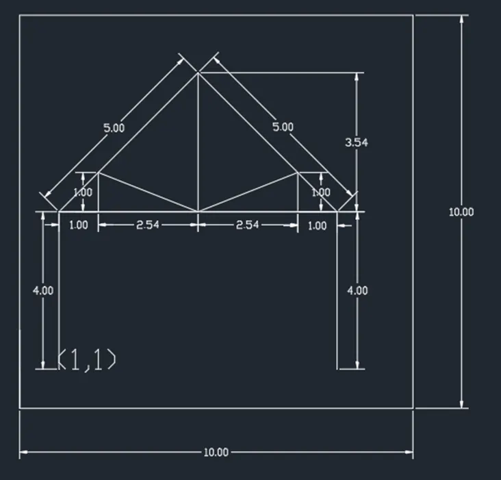
13Ans. 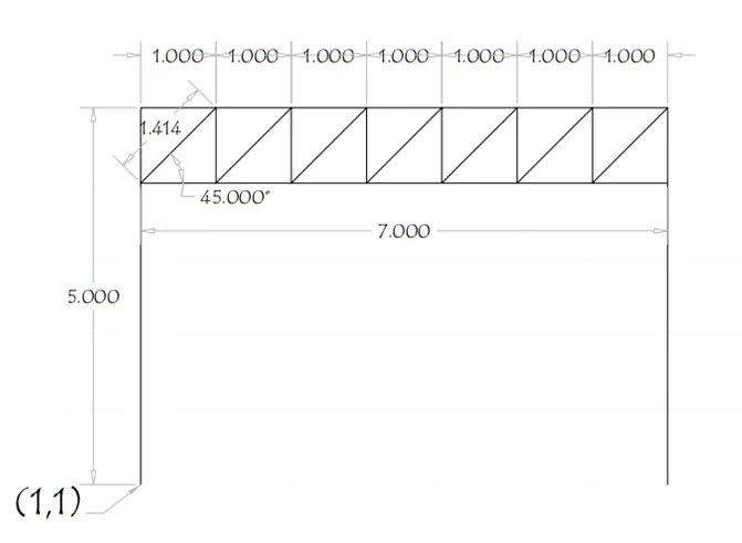
AIM- To draw the profile and the trusses using any coordinate system methods.
PROCEDURE-
- Open the AutoCAD (above 2017 version)
- Click on the Start Drawing icon. The AutoCAD window will open.
- In the command line, enter startup and then enter the value 1
- Now, go to the application menu and click on the new
- A dialogue page will appear showing create a new drawing, go to quick setup
- Now choose the units as engineering and area as 1’ x 9”
- Customize the drafting settings as per the requirements like cross hair size, color and visibility of co- ordinate data.
- Create a 10’ x 10’ rectangular box from rectangular tool bar or by line to draw the mentioned figures
Relative Polar coordinate system
- Invoke the line tool from command bar by entering L enter or line enter.
- Line- Specify first point: 1, 1
- Specify next point or undo: @5 <90
- Specify next point or undo: @7 < 0
- Specify next point or undo: @5< 270
- Invoke the line tool from command bar by entering L enter or line enter.
- Line- Specify first point: 1, 5
- Specify next point or undo: @7 < 0
- Invoke the line tool from command bar by entering L enter or line enter.
- Line- Specify first point: 1, 5
- Specify next point or undo: @1.414 < 45
- Specify next point or undo: @1 < 270
- Specify next point or undo: @1.414< 45
- Specify next point or undo: @ 1 < 270
- Specify next point or undo: @1.414 < 45
- Specify next point or undo: @1 < 270
- Specify next point or undo: @1.414< 45
- Specify next point or undo: @ 1 < 270
- Specify next point or undo: @1.414 < 45
- Specify next point or undo: @1 < 270
- Specify next point or undo: @1.414< 45
- Specify next point or undo: @ 1 < 270
- Specify next point or undo: @1.414 < 45
RESULT- Hence the result is 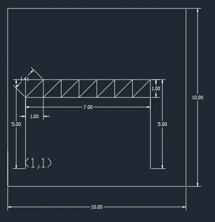
14Ans. 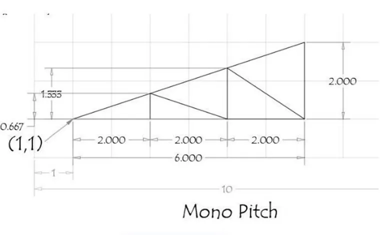
AIM- to draw the mono pitch by any coordinate system methods.
PROCEDURE-
- Open the AutoCAD (above 2017 version)
- Click on the Start Drawing icon. The AutoCAD window will open.
- In the command line, enter startup and then enter the value 1
- Now, go to the application menu and click on the new
- A dialogue page will appear showing create a new drawing, go to quick setup
- Now choose the units as engineering and area as 1’ x 9”
- Customize the drafting settings as per the requirements like cross hair size, color and visibility of co- ordinate data.
- Create a 10’ x 10’ rectangular box from rectangular tool bar or by line to draw the mentioned figures
Relative Polar coordinate system
- Invoke the line tool from command bar by entering L enter or line enter.
- Line- Specify first point: 1, 1
- Specify next point or undo: @6 < 0
- Specify next point or undo: @2 < 90
- Specify next point or undo: @6.3125< 198.43 or close
- Invoke the line tool from command bar by entering L enter or line enter.
- Line- Specify first point: 3, 1
- Specify next point or undo: @0.667 < 90
- Specify next point or undo: @2.125 < 341.64
- Specify next point or undo: @1.333 < 90
- Specify next point or undo: @2.376< 326.31
RESULT- Hence the result is
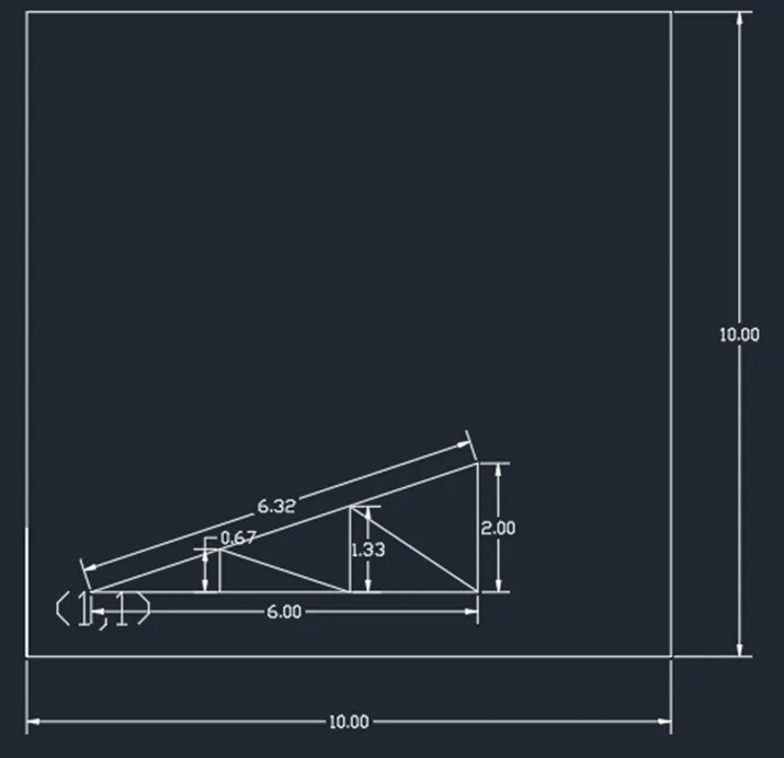
15Ans. 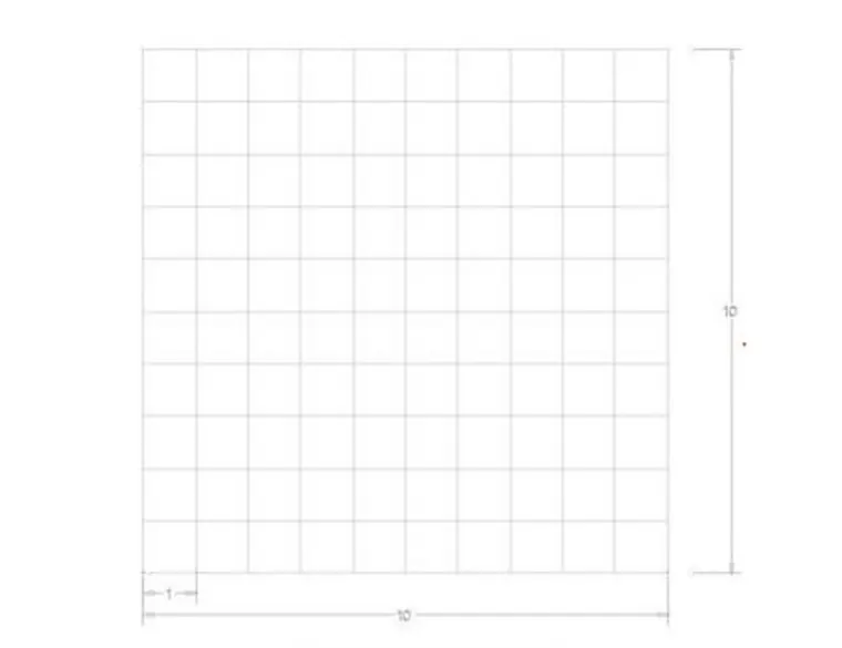
AIM- to draw the mono pitch by any coordinate system methods.
PROCEDURE-
- Open the AutoCAD (above 2017 version)
- Click on the Start Drawing icon. The AutoCAD window will open.
- In the command line, enter startup and then enter the value 1
- Now, go to the application menu and click on the new
- A dialogue page will appear showing create a new drawing, go to quick setup
- Now choose the units as engineering and area as 1’ x 9”
- Customize the drafting settings as per the requirements like cross hair size, color and visibility of co- ordinate data.
- Create a 10’ x 10’ rectangular box from rectangular tool bar or by line to draw the mentioned figures
Relative Polar coordinate system
- Invoke the line tool from command bar by entering L enter or line enter.
- Line- Specify first point: 0, 0
- Specify next point or undo: @10 < 0
- Specify next point or undo: @10 < 90
- Specify next point or undo: @10< 180
- Specify next point or undo: @10< 270
- Specify next point or undo: @1 < 0
- Specify next point or undo: @10 < 90
- Specify next point or undo: @1< 0
- Specify next point or undo: @10< 270
- Specify next point or undo: @1 < 0
- Specify next point or undo: @10 < 90
- Specify next point or undo: @1< 0
- Specify next point or undo: @10< 270
- Specify next point or undo: @1 < 0
- Specify next point or undo: @10 < 90
- Specify next point or undo: @1< 0
- Specify next point or undo: @10< 270
- Specify next point or undo: @1 < 0
- Specify next point or undo: @10 < 90
- Specify next point or undo: @1< 0
- Specify next point or undo: @10< 270
- Specify next point or undo: @1 < 0
- Specify next point or undo: @10 < 90
- Invoke the line tool from command bar by entering L enter or line enter.
- Line- Specify first point: 0, 0
- Specify next point or undo: @1 < 90
- Specify next point or undo: @10 < 0
- Specify next point or undo: @1< 90
- Specify next point or undo: @10< 180
- Specify next point or undo: @1 < 90
- Specify next point or undo: @10 < 0
- Specify next point or undo: @1< 90
- Specify next point or undo: @10< 180
- Specify next point or undo: @1 < 90
- Specify next point or undo: @10 < 0
- Specify next point or undo: @1< 90
- Specify next point or undo: @10< 180
- Specify next point or undo: @1 < 90
- Specify next point or undo: @10 < 0
- Specify next point or undo: @1< 90
- Specify next point or undo: @10< 180
- Specify next point or undo: @1 < 90
- Specify next point or undo: @10 < 0
RESULT- Hence the result is