Simulation of Shaping Machine Work Done, Equation Solver and Spring Mass Damper System Comparison Using Simulink
Aim: To make a simulink model for evaluating shaping machine workdone, equation solver and spring mass damper system comparison.
Objective:
- Generate a simulink model for evaluating workdone by a shaping machine.
- Generate a simulink model to solve a given equation with multiple variables and store result values using To File block.
- Comparison of Spring mass damper system using Simulink and Simscape.
GENERATE A SIMULINK MODEL FOR EVALUATING WORKDONE BY A SHAPING MACHINE CUTTING TOOL:
SHAPING MACHINE:
Introduction: The shaper is a machine tool used primarily for:
1. Producing a flat or plane surface which may be in a horizontal, a vertical or an angular plane.
2. Making slots, grooves and keyways
3. Producing contour of concave/convex or a combination of these
Working Principle: The job is rigidly fixed on the machine table. The single point cutting tool held properly in the tool post is mounted on a reciprocating ram. The reciprocating motion of the ram is obtained by a quick return motion mechanism. As the ram reciprocates, the tool cuts the material during its forward stroke. During return, there is no cutting action and this stroke is called the idle stroke. The forward and return strokes constitute one operating cycle of the shaper.
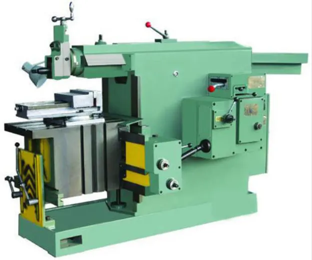
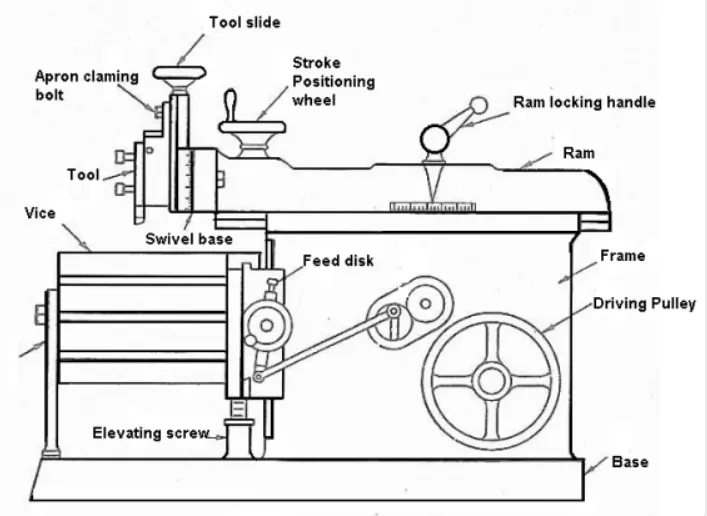
Construction: The main parts of the Shaper machine is Base, Body (Pillar, Frame, Column), Cross rail, Ram and tool head (Tool Post, Tool Slide, Clamper Box Block).
Base: The base is a heavy cast iron casting which is fixed to the shop floor. It supports the body frame and the entire load of the machine. The base absorbs and withstands vibrations and other forces which are likely to be induced during the shaping operations.
Body (Pillar, Frame, Column): It is mounted on the base and houses the drive mechanism compressing the main drives, the gear box and the quick return mechanism for the ram movement. The top of the body provides guide ways for the ram and its front provides the guide ways for the cross rail.
Cross rail: The cross rail is mounted on the front of the body frame and can be moved up and down. The vertical movement of the cross rail permits jobs of different heights to be accommodated below the tool. Sliding along the cross rail is a saddle which carries the work table.
Ram and tool head: The ram is driven back and forth in its slides by the slotted link mechanism. The back and forth movement of ram is called stroke and it can be adjusted according to the length of the workpiece to be-machined.
Simulink Model for Evaluating Workdone by Shaping Machine cutting tool.
Introduction:
To evaluate the workdone using the given parameters of a shaping machine cutting tool.

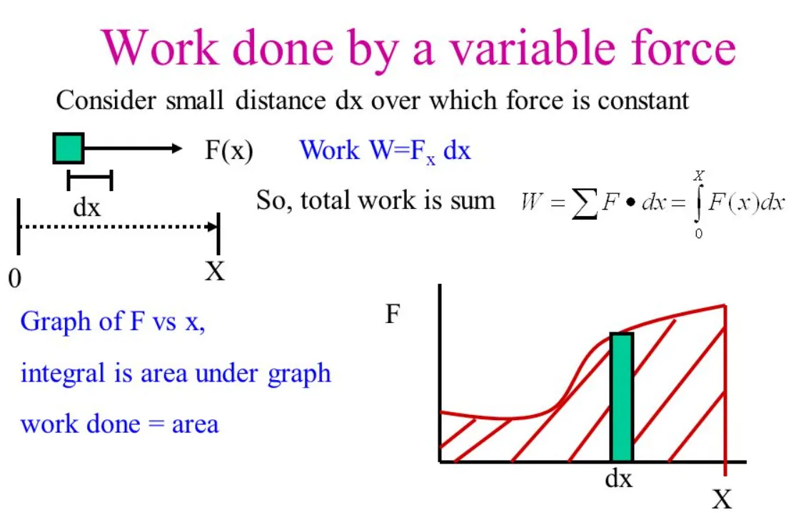
Governing Equation:
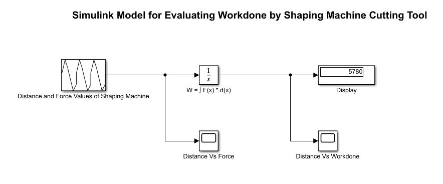
Simulink Model:
Blocks Used:
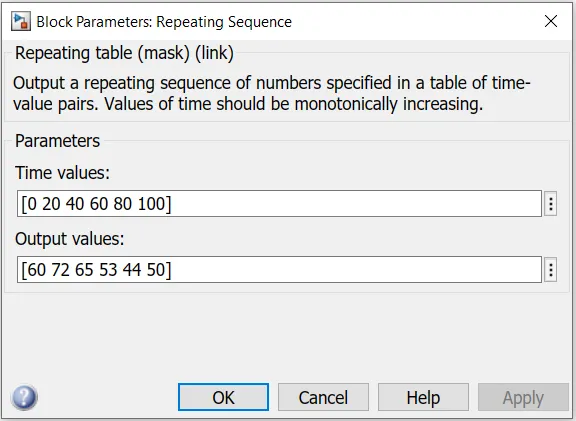
- Repeating Sequence : Inputting the distance and force value to build signal.

- Integrator : Integrate both distance and force values for obtaining the workdone value of Shaping Machine.

- Display : To View the workdone values.
- Scope : To plot Distance vs Force and Distance vs Workdone graphs.

Flow Process:
- Initially the distance (mm) and Force (KN) values inputting to the repeating sequence block to generate signals of Shaping machine for given data.
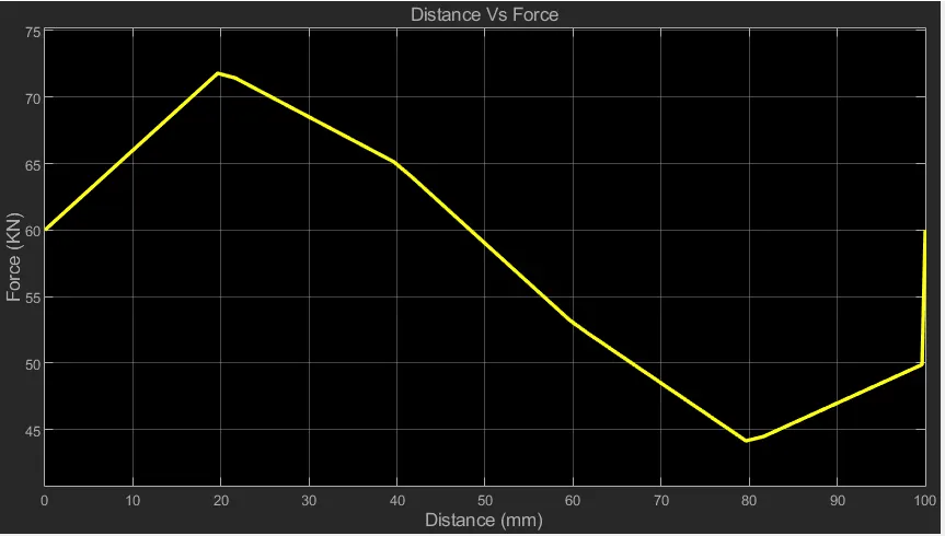
- Plotting the graph from repeating signals (Distance Vs Force) using scope.
- Next signal generated for distance and force sending to integrator block to find the workdone.
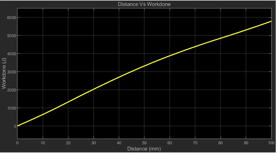
- Plotting the graph from integrator output (Distance Vs Workdone) using scope.
- Finally, displayed the output values using Display block.
Result:
Distance Vs Force
Distance Vs Workdone
Conclusion:
Generate and Evaluate the above simulink model and plotted the results Distance Vs Force and Distance Vs Workdone of shaping machine cutting tool moves through a distance of 100mm.
GENERATE A SIMULINK MODEL TO SOLVE A GIVEN EQUATION WITH MULTIPLE VARIABLES.
Introduction:
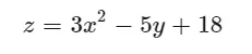
To Solve the following equation by inputting various values from array dataset as follows.

Simulink Model:
Blocks Used:
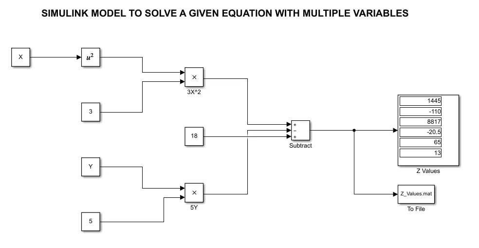
- Constant : To represent the values of 3, 5 & 18.
- Substract : For solving the equation.
- Square : For squaring the solved equation.
- Product : To evaluate and generate the function output.
- Display : To show the evaluated values.
- To File : To save the evaluated values w.r.t time interval.
Process Flow:
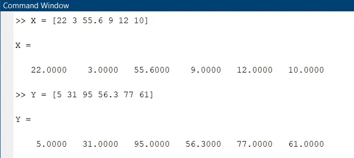
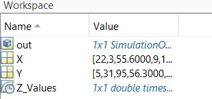
- Initially the array dataset to be inputted in the workspace for both 'X' and 'Y' Variables.
- 'X' Values from array dataset squared and then multiplied by '3' to get the values for '3X^2' .
- Then 'Y' values from array dataset multiplied by '5' to get the values for '5Y'.
- Then the final equation is solved and the values are displayed.
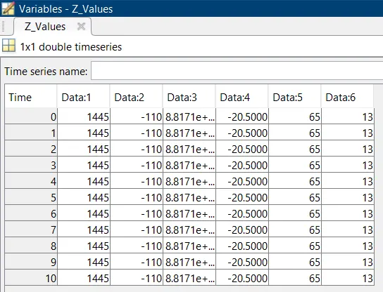
- Finally the saved values are stored in 'Z_Values.mat' file.
Result:
The equation for all the values from the dataset are solved and stored in '.mat' format file
COMPARISON OF SPRING MASS DAMPER SYSTEM USING SIMULINK AND SIMSCAPE
Introduction:
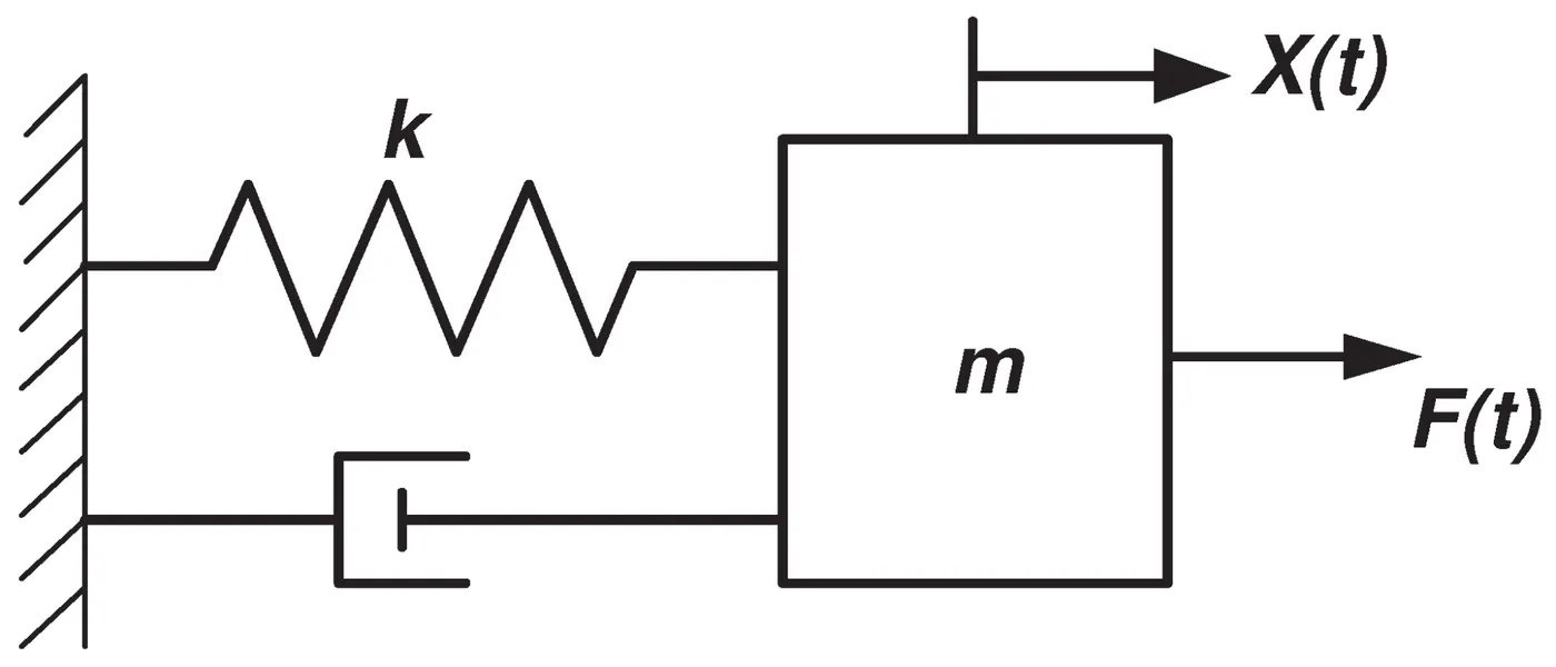
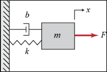
- All systems possesing mass and elasticity are capable of free vibration, or vibration that takes place in the absence of external excitation. Of primary interest for such a system is its natural frequency of vibration.
- The basic vibration model of a simple oscillatory system consists of a mass, a massless spring, and a damper.
- If damping in moderate amounts has little influence on the natural frequency, it may be neglected. The system can then be considered to be conservative.
- An undamped spring-mass system is the simplest free vibration system. It has one DOF.
Simulink
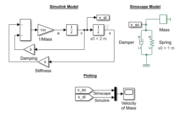
simulink is a graphical programming environment for modeling, simulating and analyzing multidomain dynamic systems. Simulink uses block diagram approach and the signal flow is Unidirectional.
Simscape
Simscape is one of the tool box in simulink’s library, simscape contains the tools which are required for simulation of physical systems modelling approach (Real Time Environment). The signal flow is bi-directional between blocks.
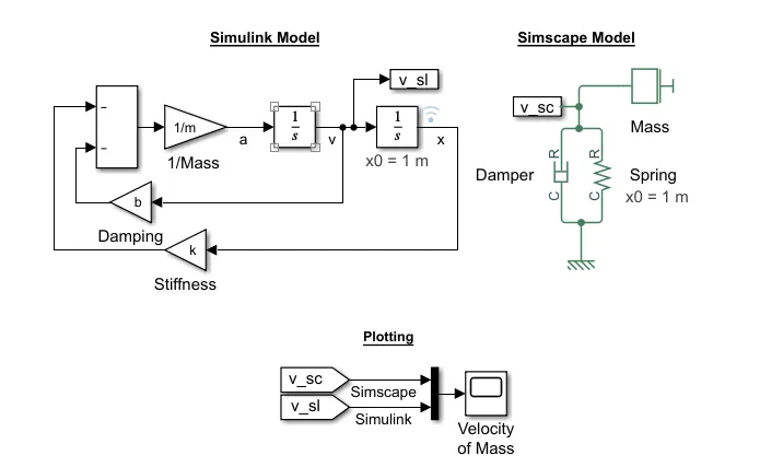
SIMULINK AND SIMSCAPE MODEL:
Blocks Used:
- Gain: To multiply with constant value to the input given.

- Substract: For solving the equation.

- Integrator: To integrate the velocity and distance values.

- Goto: To send the signal from any subsystem or in main model to any place.

- From: To receive the sent signal from Goto block.

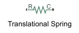
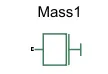
- Damper, Spring, Mass: To model a spring mass damper system.
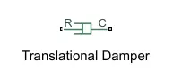
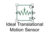
- Ideal translational motion sensor: To sense the movement(velocity) of the system.
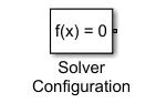
- Solver Configuration: It specifies the solver parameters before starting the simulation.
- Mechanical Reference: To make sure that all the components are clamped to the ground.
Flow Process:
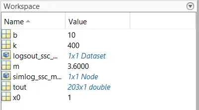
- The mass(m), spring constant(k), damping co-efficient(b) and spring displacement (x0=1) are inputted from the MATLAB workspace window.
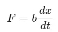
- Then the damping force is generated from the entered damping co-efficient(b) and velocity.
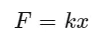
- Next the spring restoration force is generated by the entered spring constant(k) and the distance(x).
- Then both the forces are subtracted because it's in the opposite direction.
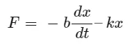
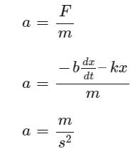
- Now acceleration is calculated.
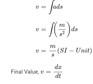
- Then the velocity is calculated by integrating,
- This process continues according to the input value (b,k and m).
Result:
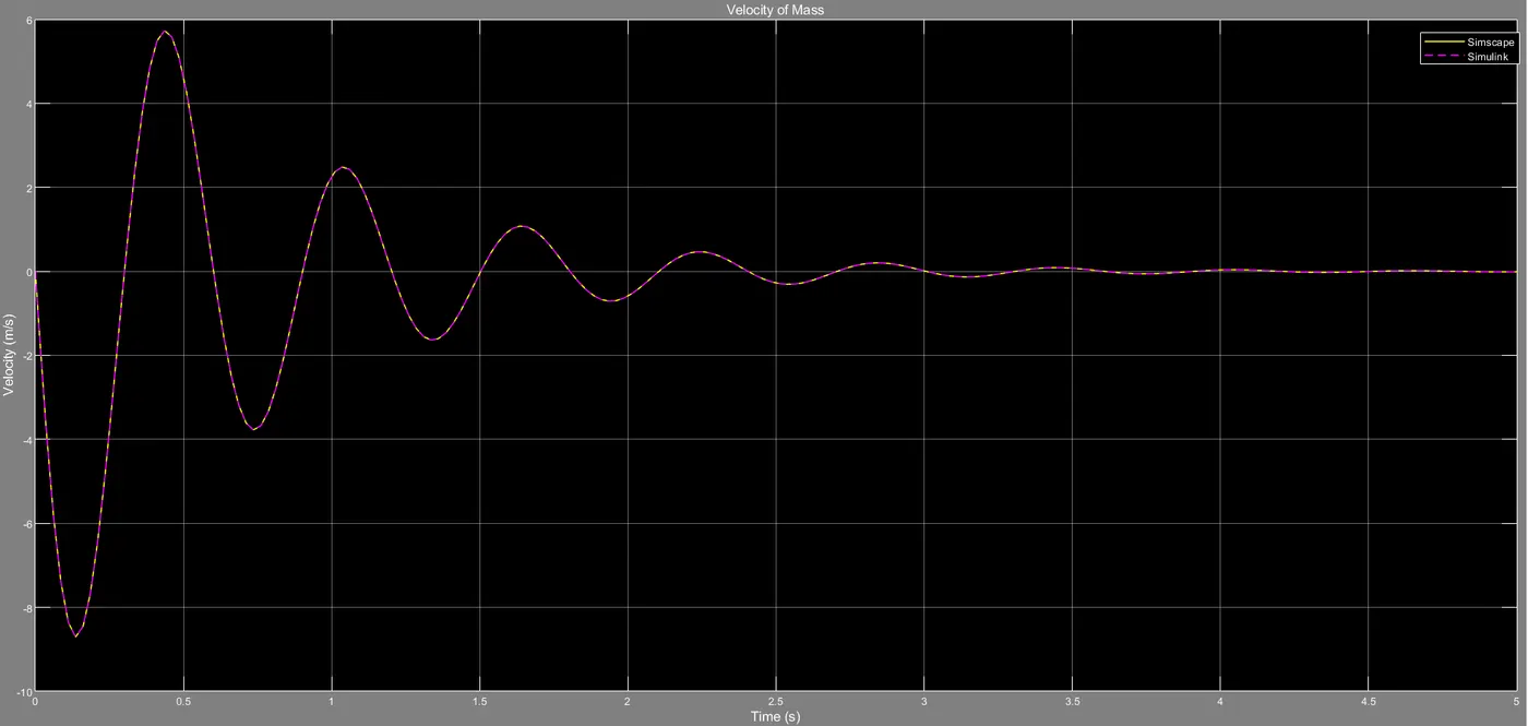
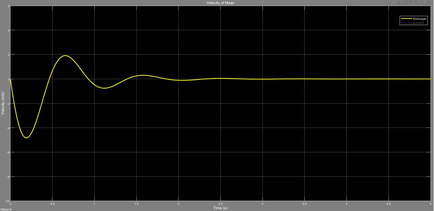
Here both the velocity of Simulink and Simscape are same because there is no change in any parameters in the system.
Task 1 - Derivation of Governing Equation:
In this model we are using Spring Mass Damper System with Simple Harmonic Motion.
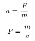
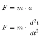
From Newton's second law of motion.
The forces acting on the system are,
Force for movement,
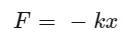
The restoration force of spring i.e, returning to equlibrium position.
Resistive force for movement,
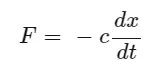
The damping force in the system.
Velocity,
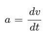
Now,
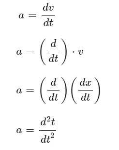
Force,
By equating,
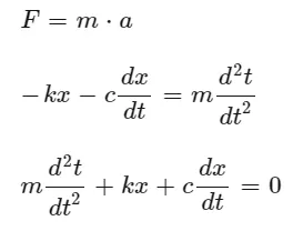
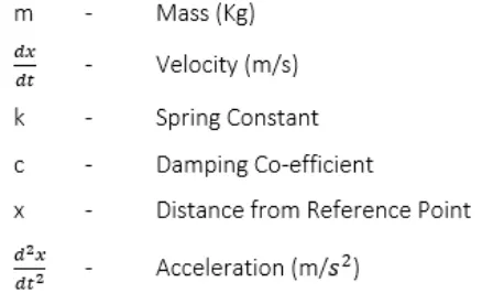
Where,
Task 2 - Changing the parameters in Simulink Model:
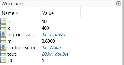
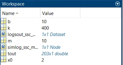
The parameters being changed in the simulink model are mass (m), initial spring position (x0=2) and the plot the results,
Original Parameters Changed Parameters
Simulink Model:
Result:
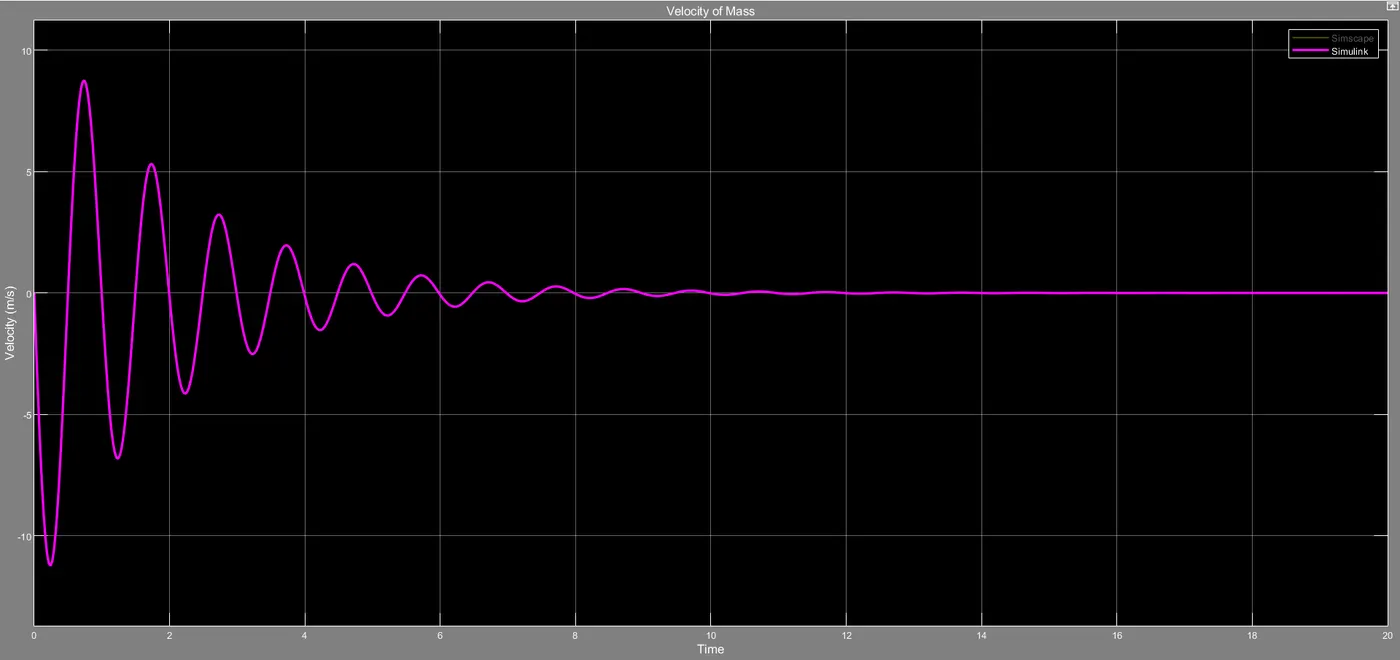
Task 3 - Changing the parameters in Simscape Model:
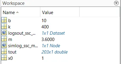
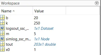
The parameters being changed in the simulink model are mass (m), initial spring position (x0=2) and the plot the results,
Original Parameters Changed Parameters
Simscape Model:
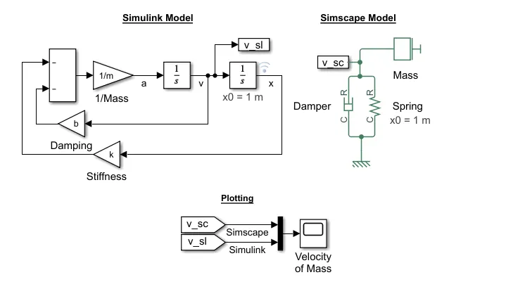
Results:
REFERENCES:
- https://in.mathworks.com/help/physmod/simscape/ug/mass-spring-damper-in-simulink-and-simscape.html?s_tid=srchtitle
- http://www.sharetechnote.com/html/DE_Modeling_Example_SpringMass.html