Simulation of a backward facing step in OpenFOAM
Aim : To simulate an incompressible-laminar-viscous flow through the backward facing step geometry. There are 2 case studies.
Case 1 - Simulate the flow without using any grading factor (i.e., GF = 1)
Case 2 - Simulate the flow with grading factor of 0.2. The cells should be finer near the walls (includig the step wall).
Also, Measure the velocity profile at 0.085 m from the inlet of the geometry for both case studies and compare and Explain why Grading/Growth factor is essential for meshing.
Introduction to the problem specifics : OpenFoam is used for the flow analysis in this case study. OpenFoam is a open source computational fluid dynamics software. Here you refer the source code behind every command and understand how it works. We can solve FVM based problems using it which is a form of numerical discretization. OpenFoam consists of tutorials folder which has various solvers in it. We have to judge on the basis of the nature of problem which solver to be used to solve the problem. First we open the command line interface and type 'tut' , and then press 'ls' hit enter.
we will get the list of the tutorials. Then we have to copy-paste the solver file in 'run' folder and make changes according to the problem statement in 'run' folder. We should not be making any changes in Tutorials folder, we might not even be allowed to do so by OpenFoam because it will changes the configuration of the solvers and we may to re-install OpenFoam to get correct results.
Procedure :
The first step in this project is that to define the geometry and we do that by giving inputs in blockMeshdict file.
Now, we define the geometry by specifying the vertices of it as following figure. To specifying the geometry we follow the path as follows:
'run' > 'cd cavity' > 'cd system' > 'gedit blockMeshdict' and we will get the screen as follows :
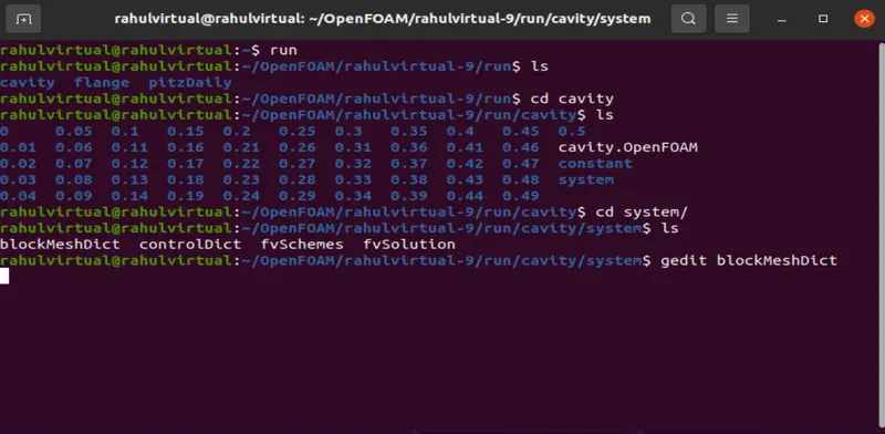
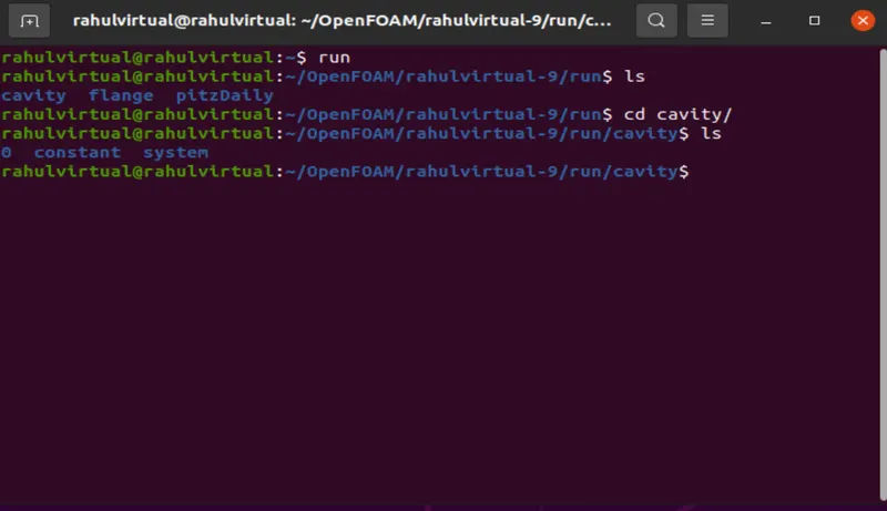
initially when we copy the cavity file to the run folder , inside we get three main files as 0 , constant , system
0 contains the initial conditions of the solver
constant folder specifies the mesh information generated after blockMesh command.
system folder has the information of type of solver we used and the equations we are solving.
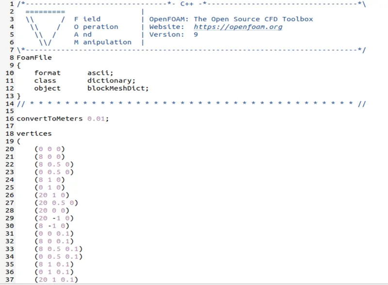
the vertices are specified as follows :
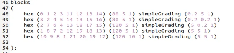
then we specify the faces of the blocks by the block command. we do it in such a way that the order of the vertices specifying the face corresponds to the right hand thumb rule. the snipshot is as follows :
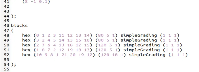
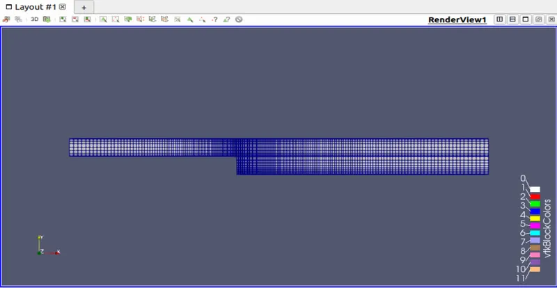
the grading factor of 0.2 is given as follows :
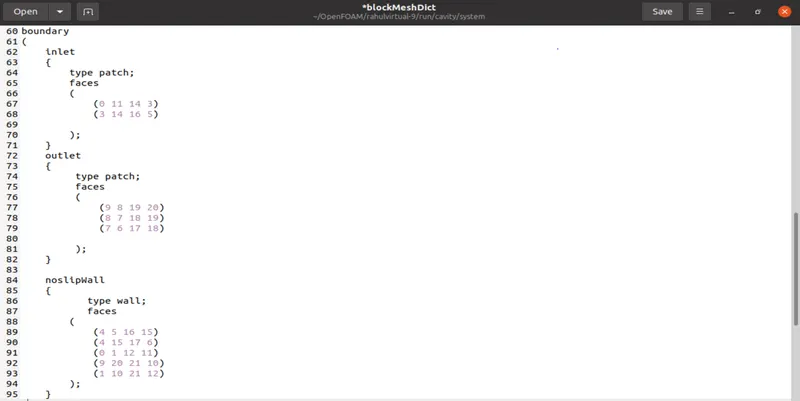
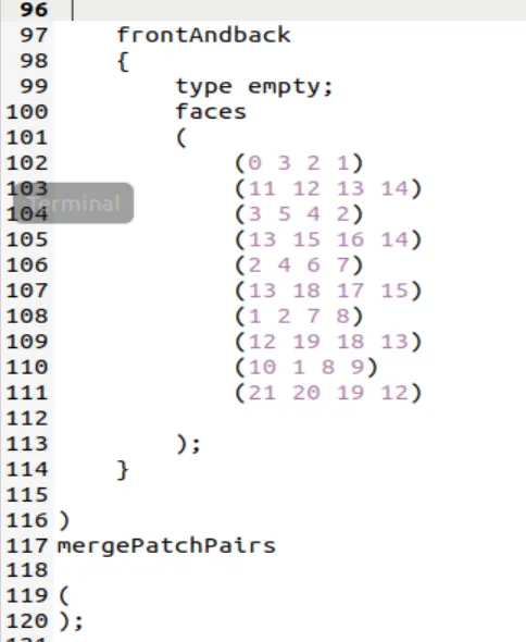
Now, specifying the boundary conditions as follows : the inlet faces of the geometry is named as inlet and the vertices are specified using right hand rule. Same as to the outlet and other walls. At the end we merge the patches using merge command.
(80 5 1) and (120 5 1) given beside the hex command specifies the number of mesh points along the x-axis and y-axis.
the command specified above will also generate the mesh with a grading factor of 1. 'simpleGrading' command is used here.
suppose we want to change the grading factor along x-axis so the ratio of size of end cell to the size of start cell gives the grading factor for that particular axis. so a grading factor of simpleGrading(0.1 1 1) will provide finer mesh as we move along the x-axis and simpleGrading(10 1 1) will provide coarser mesh as we move along x-axis.
after generation the mesh through blockMesh command we get the screen as follows :
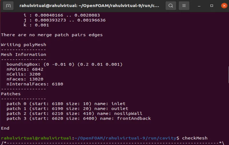
The execute the solver and get the screen as follows :
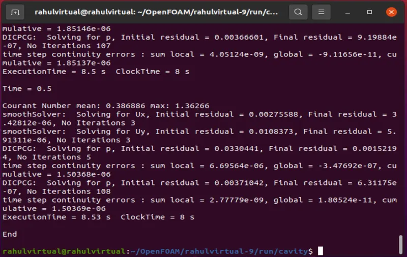
we need to keep the courant no less than or equal to 1 so as to get stable results.
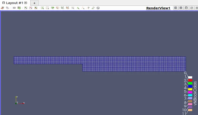
the geometry can be seen as follows in the ParaFoam:
the geometry with mesh grading factor 0.2 :
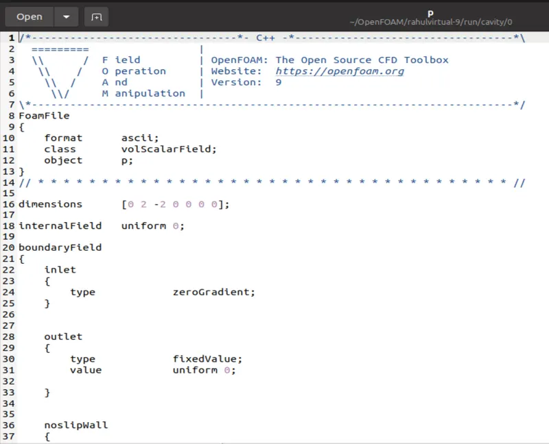
After now we will move to define the kind of solutions we want to out of this geometry. we first provide initial conditions. For that we navigate to the '0' folder. It has 2 files. in pressure file we specify the conditions as follows :
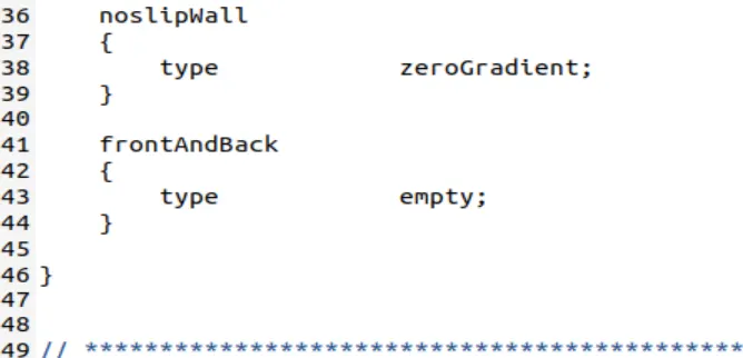
and velocity profile is as follows :
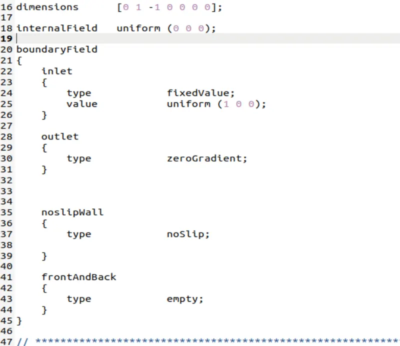
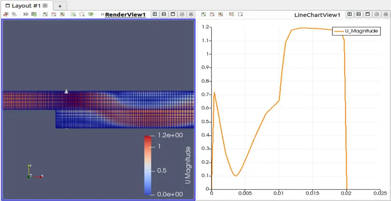
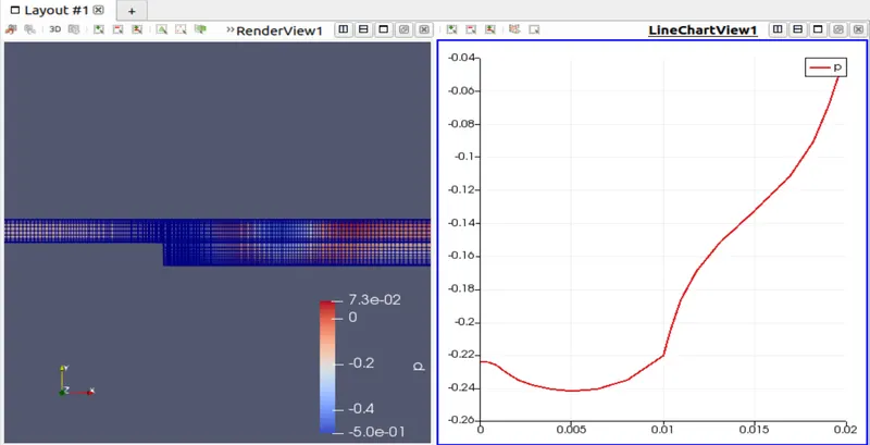
the velocity and pressure profile captured in the Paraview is as follows :
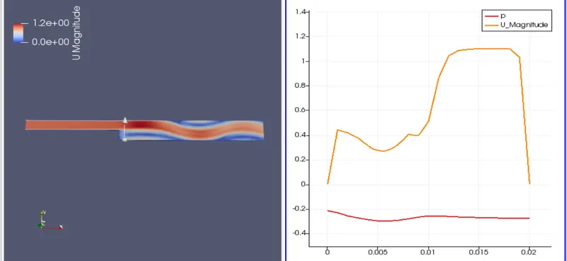
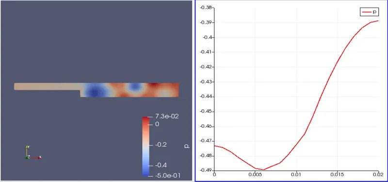
simulation result of backward step with mesh grading factor 0.2 :
velocity profile :
pressure profile :
Grading Factor : It is used to produce the mesh fine or coarse along the particular axis. The regions in geometry where there is abrupt change in the contours or the geometry is complex , there we can produce mesh as fine so that we could capture the results accurately.