Air standard cycle representation using Matlab
Aim :
- to generate a P-V diagram of Otto Cycle.
- to determine the thermal efficiency of Otto Cycle.
Introduction:
Otto cycle denotes the thermodynamic relationship of a Piston Engine.
The Presssure,volume,temperature variations inside the Piston engine can be
easily visualised through the P-V diagram.
The stages of otto cycle explained below:
From stage 1 to stage 2 = there is Isentropic compression.
From stage 2 to stage 3 = there is constant volume heat addition.
From stage 3 to stage 4 = there is Isentropic expansion.
From stage 4 to stage 1 = there is constant volume heat rejection.
note : by isentropic means that the entropy of the system remains same so the heat is drawn from the engine just as much as to compensate the friction so as to leave the entropy unchanged.
Solution :
the volume, pressure,temparature is denoted by v_n ,p_n ,t_n,respectively for various stages. n being the respective integers.
suppose given,
bore = 0.1;
stroke = 0.1;
con_rod = 0.15;
cr = 12
p1 = 101325 pascal
t1 = 500 Kelvin
compression ratio = 12
then,
swept volume = `(pi/4)*(b)^2*stroke` where b = bore,
clearance volume = `(swept *volume)/(c_r-1)`
we calculate v1 and v2 by the given values of swept volume and clearance volume.
v1 = swept volume + clearance volume = total volume
v2 = clearance volume = volume at top dead centre.
by the relation :
`(p_m*v_m)^gamma = (p_n*v_n)^gamma`
and `(p_m*v_m)/(t_m) = (p_n*v_n)/t_n`
where m and n are consecutive integers.
the formula for how the volume inside the combustion chamber is going to change is given by=
`V/V_c = 1 + 1/2(c_r - 1)[R+1-cos theta-(R^2-sin^2theta)^(1/2)]`
V_c = clearance volume.
R = ratio of connecting rod length to crank pin radius (a).
crank pin radius (a) = stroke/2
Code theory =
here we used "function" command to call the inputs when needed to compute the volume varies as the engine undergoes compression and expansion.
and then plotted it by "plot" command.
when we call the function it is made sure that the name of function and the name of file saved as the code is same.
while coding for the instantaneous volume, the formula is divided in 3 parts as term 1,2,3 and then computed.
the iteration for crank position has been given as 100, so 100 values will be generated for the cycle from start to end of the crank position.
this is implimented by assigning values to the array "theta" in function through "linspace" command.
the thermal efficiency is then calculated by the formula as =
`1-(1/c_r)^(gamma-1)*100`
thermal efficiency = 62.9893 %
the code for the air standard cycle is given as follows:
clear all
close all
clc

%otto_cycle

%inputs
p1 = 101325
t1 = 500
gamma = 1.4
t3 = 2300

%engine_parameters
bore = 0.1;
stroke = 0.1;
con_rod = 0.15;
cr = 12

%calculating swept volume and clearance volume
v_swept = (pi/4)*bore^2*stroke;
v_clearance = v_swept/(cr-1);

v1 = v_swept + v_clearance
v2 = v_clearance
constant_c = p1*v1^gamma;

V_compression = engine_kinematics(bore,stroke,con_rod,cr,180,0);

P_compression = constant_c./V_compression.^gamma


%state variables for state point 2
%p2*v2^gamma = p1*v1^gamma

p2 = p1*cr^gamma;

t2 = p2*v2*t1/(p1*v1);


%state variables at state point 3
v3 = v2;

p3 = p2*v2*t3/(t2*v3);

constant_c = p3*v3^gamma;

V_expansion = engine_kinematics(bore,stroke,con_rod,cr,0,180);

P_expansion = constant_c./V_expansion.^gamma

%state variables at state point 4
v4 = v1

%p3*v3^(gamma) = p4*v4^(gamma);

p4 = p3*(v3/v4)^(gamma);

figure(1)
hold on
plot(v1,p1,'*','color','r')
plot(V_compression,P_compression)
plot(v2,p2,'*','color','r')
plot([v2 v3],[p2 p3])
plot(v3,p3,'*','color','r')
plot(V_expansion,P_expansion)
plot(v4,p4,'*','color','r')
plot([v4 v1],[p4 p1])


% thermal efficiency

E = thermal_efficiency = (1-(1/cr)^(gamma-1))*100;

xlabel('volume')
ylabel('pressure')
grid on
title('P-V GRAPH')
the code for the function command for 'engine kinematics' which carries the inputs and executed when called is given as follows:
function [V] = engine_kinematics(bore,stroke,con_rod,cr,start_crank,end_crank);


     a = stroke/2;
     R = con_rod/a;

     v_swept = (pi/4)*bore^2*stroke;
     v_clearance = v_swept/(cr-1);

     theta = linspace(start_crank,end_crank,100);

     term1 = 0.5*(cr-1);
     term2 = R+1-cosd(theta);
     term3 = (R^2-sind(theta).^2).^0.5;
     V = (1 + term1*(term2-term3)).*v_clearance;
end
the graphical representation for otto cycle is given is follows:
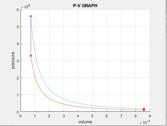
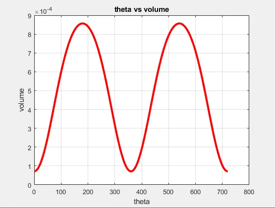
if we plot a graph of theta versus volume,and theta being the value of 2 cycles of crank shaft.
the code for it is as follows:
clc
close all
clear all

con_rod = 0.15;
bore = 0.1;
cr = 12
stroke = 0.1;
a = stroke/2;
R = con_rod/a;


v_swept = (pi/4)*bore^2*stroke;
v_clearance = v_swept/(cr-1);

theta = linspace(0,720,720);


term1 = 0.5*(cr-1);
term2 = R+1-cosd(theta);
term3 = (R^2-sind(theta).^2).^0.5;

V = (1 + term1*(term2-term3)).*v_clearance;

plot(theta,V,'linewidth',3,'color','r')
title('theta vs volume')
xlabel('theta');
ylabel('volume');
grid on
the graph for the same is follows:
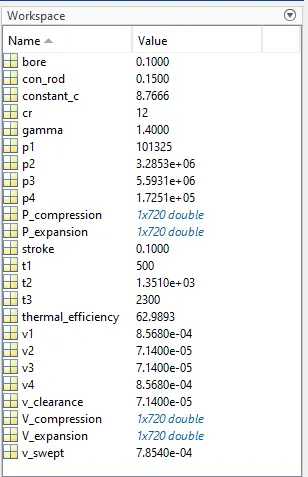
the workspace for the code is as follows:
Conclusion :
Hence we see that the theta versus volume graph is generic.
hence the pv graph is plotted and thermal efficiency is calculated.