Simulating Fluid Sloshing effect inside a Gear-box
Objective:
To perform the four simulations to analyse the slosh and flow pattern of lubricant in the gear box and then to compare the results among all the four cases.
Part 1:
- 20% Immersion, Fluid - Engine oil.
- 30% Immersion, Fluid- Engine oil.
- 20% Immersion, Fluid-n-heptane (c7h16).
- 30% Immersion, Fluid-n-heptane (c7h16).
Part 2:
- What is Dynamic meshing? Give some other examples where dynamic meshing can be used.
- What is the fluid Sloshing effect? Discuss whether the sloshing effect is good or bad? Explain.
- What is the use of UDF?
- Discuss the common errors that occurred in the simulation. A] 'Dynamic mesh failed' error. B] 'Negative cell volume detected' error.
Description:
Gear drives are used for transmitting power from one rotating shaft to another which are separated by a small distance which is the most efficient way of transmitting power. During this process due to friction between the teeth of the gear, heat will be developed which also may leads to wear of teeth.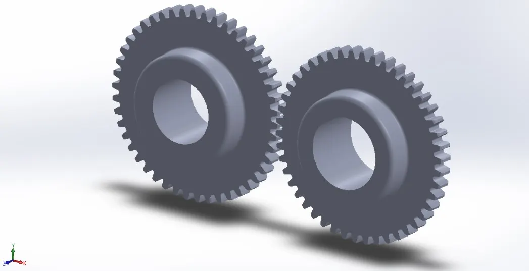
A lubricant is a substance, usually organic, introduced to reduce friction between surfaces in mutual contact, which ultimately reduces the heat generated when the surfaces move. It may also have the function of transmitting forces, transporting foreign particles, or heating or cooling the surfaces. The property of reducing friction is known as lubricity.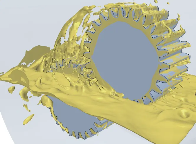
The name itself defines that a box containing gears is known as gear box. The gearbox is a mechanical method of transferring energy from one device to another and is used to increase torque while reducing speed.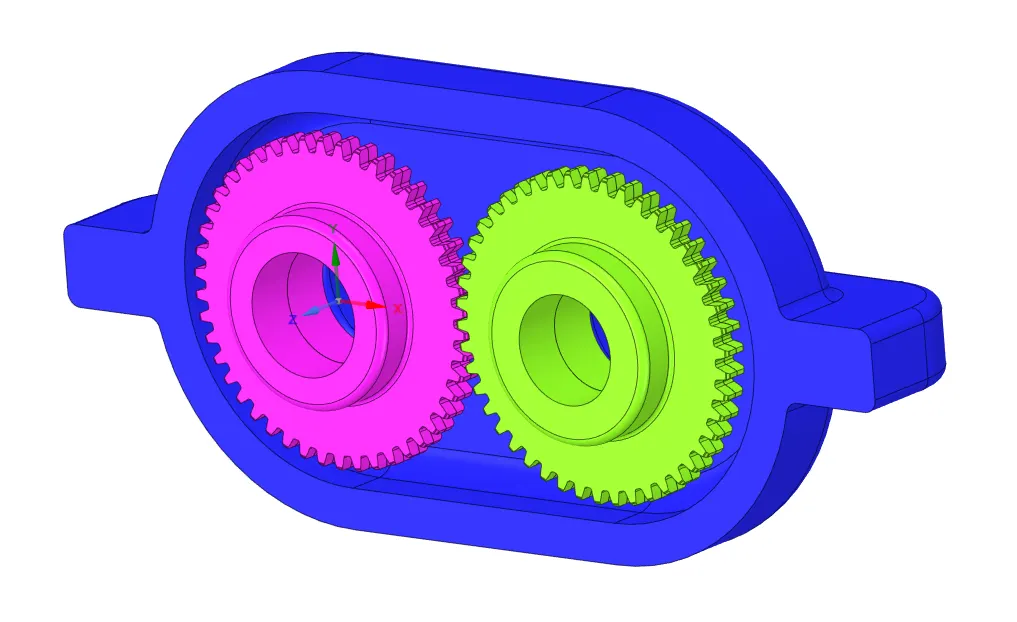
Gearboxes are used in many applications including machine tools, industrial equipment, conveyors, and really any rotary motion power transmission application that requires changes to torque and speed requirements.
Lubricant Properties:
Engine-oil
Density (Kg/m3): 889
Viscosity (Kg/m-s): 1.06
n-heptane (C7H16)
Density (Kg/m3): 684
Viscosity (Kg/m-s): 0.000409
Geometry:
The gear box model has been imported into the space claim of fluent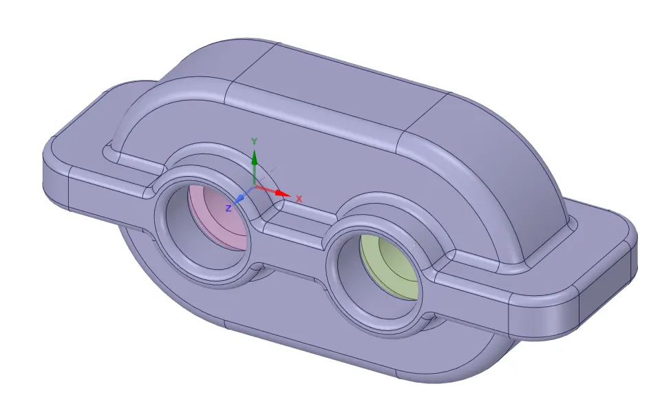
Fluid volume is extracted from it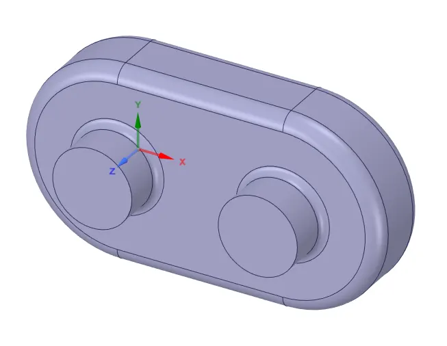
2D surface is extracted from the fluid volume and the entire simulation is done on this 2D surface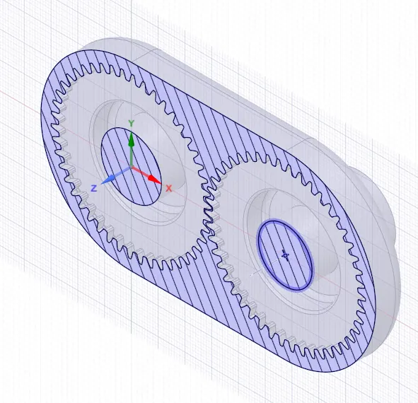
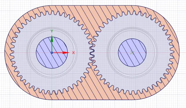
Meshing: Triangular mesh
Element size: 0.75mm
Number of elements: 36680
Element quality >66%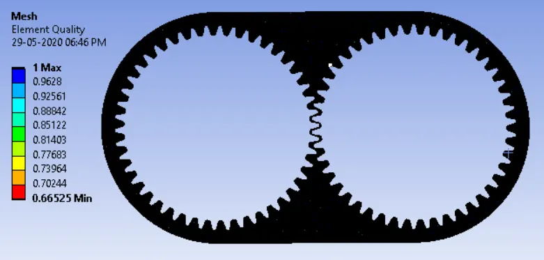
Setup & Solution:
Solver type: Pressure based
Time: Transient
Enable gravitation in -Y axis
Materials: Air
case1&2 – Engine oil
case3&4- n-heptane(C7H16)
Viscous model: k-epsilon standard
Multiphase model > Volume of fluid > Implicit method
Phases: Primary – Air (all cases)
Secondary- case1&2 – Engine oil
case3&4 - n-heptane(C7H16)
In user defined > functions > compiled > load the UDF code “rate.c” > build
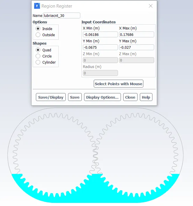
Domain > Adapt > Check Dynamic adaption and create new cell register
Case1&3 – 20% of lubricant in the gear box
Case2&4– 30% of lubricant in the gear box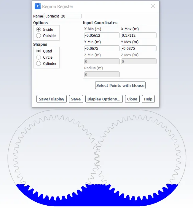
Domain > Dynamic mesh > enable dynamic mesh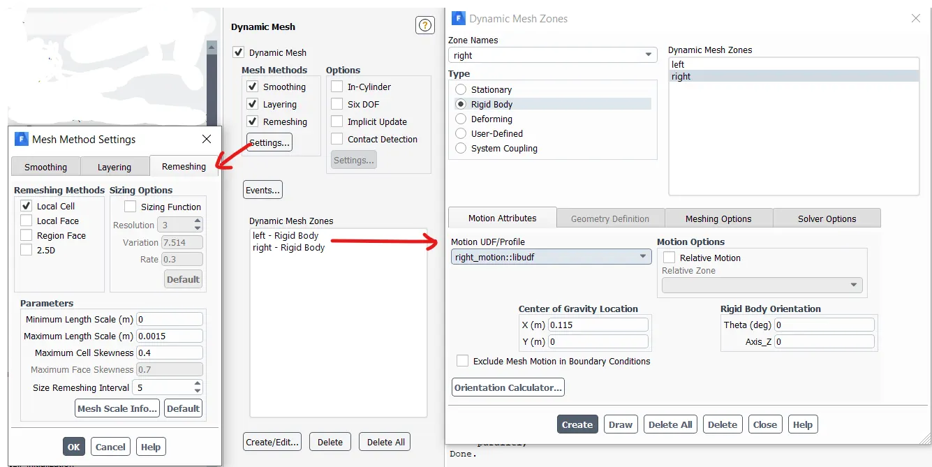
Initialization: Hybrid
Patch secondary phase with 1
Time step size: 5e-05
No. of steps: 1300
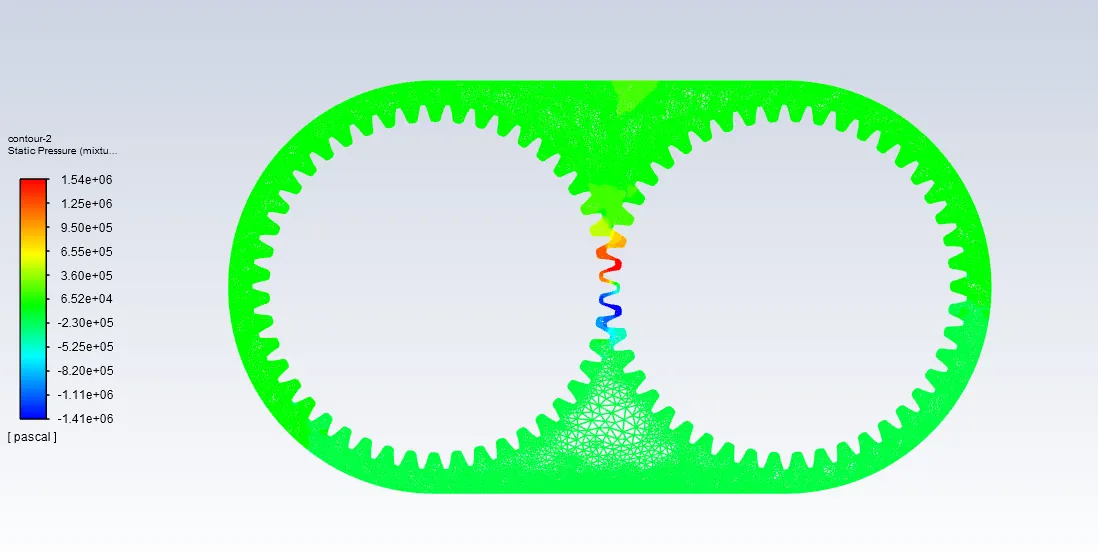
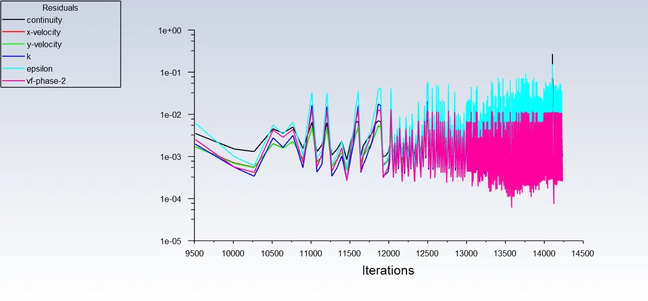
1. Engine-oil @ 20% immersion
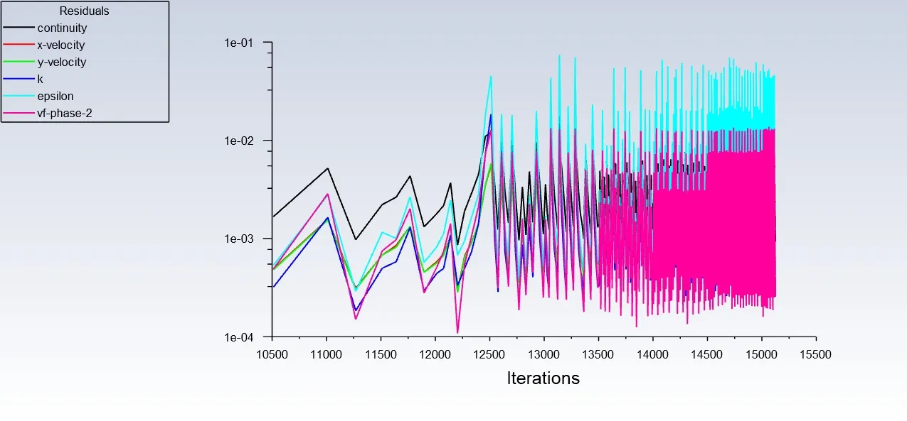
2. Engine-oil @ 30% immersion
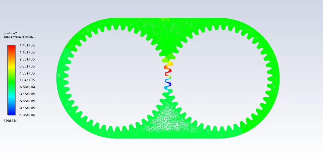
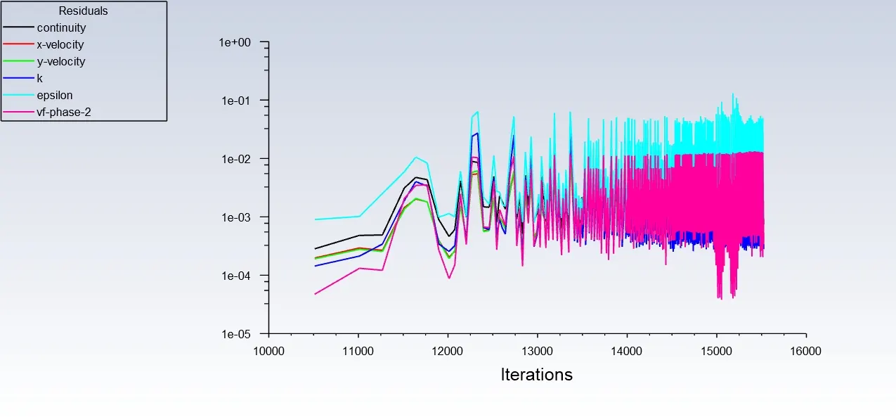
3. n-heptane @ 20% immersion
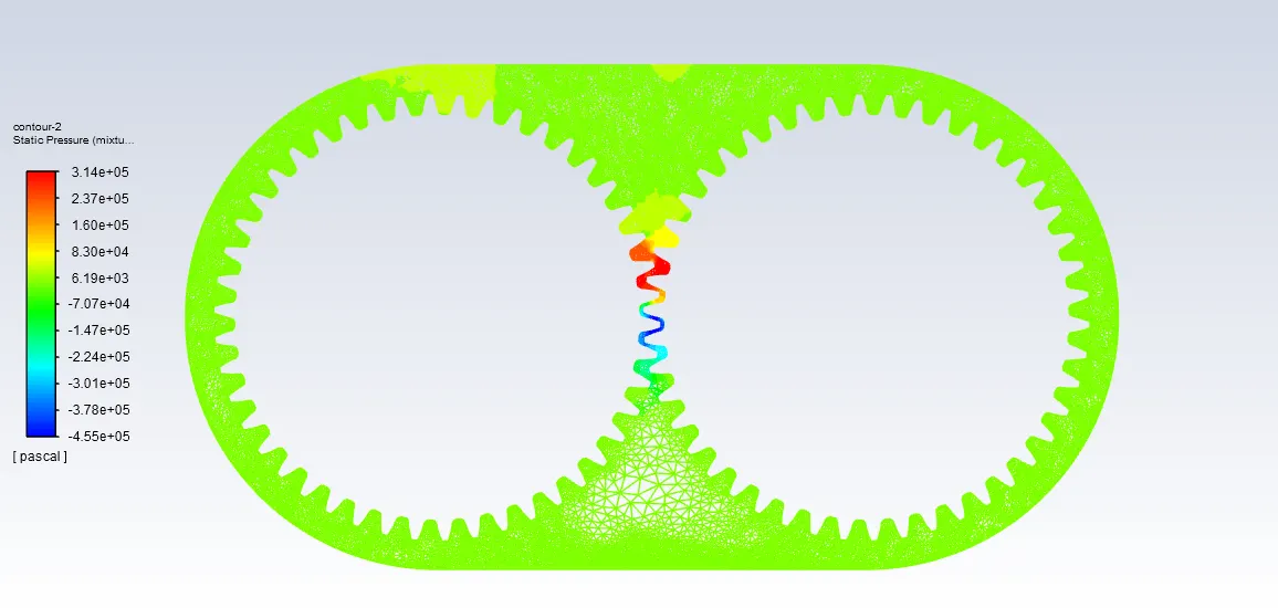
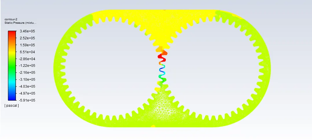
4. n-heptane @ 30% immersion
Conclusion:
Engine oil vs n-heptane:
1. Density of engine oil is greater than that of n-heptane. hence engine oil tries to slide downwards therefore complete lubrication of teeth surface will not take place..
2. During the rotation of shafts heat is generated between the teeth. The viscosities of most liquids decrease with increasing temperature and increase with increasing pressure. Therefore engine oil will show more lubrication property for longer time than n-heptane by sticking to the teeth suface
20% vs 30% immersion:
1. In case of 20% of immersion of gear in lubricant, minimum no. of teeth will carry lubricant with it which leads to friction.
2. In case of 30% of immersion of gear in lubricant, more no. of teeth will carry lubricant with it which helps in reducing friction.
Therfore, engine oil with 30% immersion of gears is preffered.
Part-2
1.What is Dynamic meshing? Give some other examples where dynamic meshing can be used.
Dynamic Mesh Module is a tool that allows the motion of parts (or subparts) relative to static ones, which therefore makes the fluid volume changing in time frame. In dynamic mesh model the boundaries of a cell zone are allowed to move relative to other boundaries of the zone, and to adjust the mesh accordingly. The boundaries can move rigidly with respect to each other (that is, linear or rotational motion), and/or deform.
The motion of the boundaries can be:
- Rigid - Pistons moving inside an engine cylinder or a flap deflecting on an aircraft wing.
- Deforming - The elastic wall of a balloon during inflation or a flexible artery wall responding to the pressure pulse from the heart.
In either case, the nodes that define the cells in the domain must be updated as a function of time, and hence the dynamic mesh solutions are inherently unsteady.
An important special case of dynamic mesh motion is called the sliding mesh in which all of the boundaries and the cells of a given mesh zone move together in a rigid-body motion. In this situation, the nodes of the mesh move in space (relative to the fixed, global coordinates), but the cells defined by the nodes do not deform.
The mesh Smoothing and Remeshing techniques, provide instant mesh deformation capability. Remeshing is used when the mesh is more sensitive to mesh changes, which can be used to manually specify ranges of maximum and minimum elements in the Maximum and Minimum Length Scale for mesh changes.
In the Dynamic Mesh Zone section, areas or boundaries of the model that should be affected by the mesh change must be defined, such as by Deforming to change the boundaries in the area (fluid around a moving object or a boundary-changing object), Rigid Body to moving physical boundary and moving boundaries but not boundaries themselves, from Stationary to fixed body and finally from System Coupling to FSI solution.
Generally, the dynamic mesh technique is used when simulating models that require a moving mesh area. Whenever the problem model was such that the fluid zone required mesh moment changes over time, the Dynamic Mesh technique will be used.
The dynamic meshing can be used to model flows where:-
- The shape of the domain is changing with time due to motion on the domain boundaries.
- Six DOF dynamic mesh for modelling variation of location and angle of ship and boat in wavy sea situation.
- Simulation of the tidal turbine using six DOF dynamic mesh method (calculating rotation speed).
- Releasing of food box from airplane using six DOF dynamic method.
- Simulation of globe valve movement during the time.
- Train movement in the tunnel by variable velocity function in a urban tunnel.
- Simulation of flap movement of an airplane wing.
- Modelling the underwater vehicle in Submerged and non-submerged situation.
- Solid fuel combustion and modelling solid height level during burning fuel.
- Fluid solid interaction of blood flow and vessel.
- FSI simulation blood flow pumping in human heart.
- Fluid solid interaction of airflow around building and finding final deflection and fluctuation (two way and one way FSI)
- Two and four-stroke internal combustion engine.
- Automotive piston moving.
- Gearbox.
Advantages
-
This model enables the spatial variation of the defined areas for fluid flow and allows the mesh of the region at the same time as the spatial location of the points and boundaries of the region changes compatibility with the place at the present moment.
- Boundaries or motion of objects can be moved based on in-cylinder motion (RPM, stroke length, crank angle,etc), Prescribed motion via profiles or UDF, Coupled motion based on hydrodynamic forces from the flow solution, via FLUENT’s 6 DOF model.
-
The dynamic mesh model can be applied to single or multiphase flows (and multi-species flows).
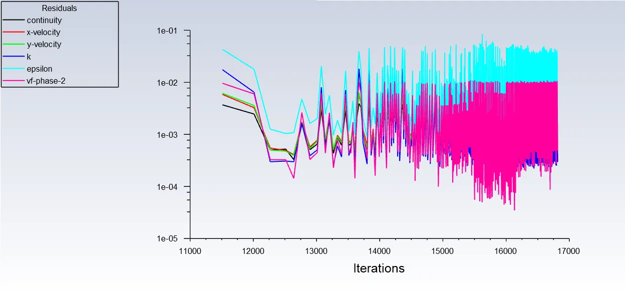
Disadvantage -Inaccurate remeshing settings under dynamic mesh may lead to error - update dynamic mesh failed. Negative cell volume detected. and Floating point exception error. This may happen because remeshing may be too coarse.
Q2. What is sloshing and explain whether the sloshing effect is good or bad for any applications?
In fluid dynamics, sloshing refers to the movement of liquid inside another object (which is, typically, also undergoing motion). The liquid must have a free surface to constitute a slosh dynamics problem, where the dynamics of the liquid can interact with the container to alter the system dynamics significantly.
For example propellant slosh in spacecraft tanks and rockets (especially upper stages), and the free surface effect (cargo slosh) in ships and trucks transporting liquids (for example oil and gasoline). However, it has become common to refer to liquid motion in a completely filled tank, i.e. without a free surface, as "fuel slosh".
Such motion is characterized by "inertial waves" and can be an important effect in spinning spacecraft dynamics. Extensive mathematical and empirical relationships have been derived to describe liquid slosh. These types of analyses are typically undertaken using computational fluid dynamics and finite element methods to solve the fluid structure interaction problem, especially if the solid container is flexible. Relevant fluid dynamics non-dimensional parameters include the Bond number, the Weber number, and the Reynolds number.
Slosh is an important effect for spacecraft, ships, and some aircraft. Slosh was a factor in the Falcon 1 second test flight anomaly, and has been implicated in various other spacecraft anomalies, including a near-disaster with the Near Earth Asteroid Rendezvous (NEAR Shoemaker) satellite.
Sloshing is also a periodic motion of the free surface of the liquid in a partially filled tank or container that can be caused by several factors. It is viewed in many applications. In freely slosh it can produce forces that cause instability, rollover, and failure or damage in tank or container in some cases. Baffles used as sloshing suppression devices. The severity of sloshing and its dynamic pressure loads depend on the tank geometry, the depth of the liquid, the amplitude and the nature of the tank motions. They also depend on the frequency of excitation over a range of frequencies close to the natural frequency of the fluid.
Sloshing of liquid in the storage tank may result in negative effects such as deformation and failure of tank walls due to impact. If an open tank is subjected to ground motions, sloshing may lead to liquid spillage. Therefore, sufficient clearance need to provide between the free surface and top of the tank or roof must be provided.
Liquid sloshing strongly influences the directional dynamics and safety performance of highway tank vehicles in a highly adverse manner.
Hydrodynamic forces and moments arising from liquid cargo oscillations in the tank under steering and/or braking maneuvers reduce the stability limit and controllability of partially-filled tank vehicles.
Anti-slosh devices such as baffles are widely used in order to limit the adverse liquid slosh effect on directional performance and stability of the tank vehicles.
Sloshing or shifting cargo, water ballast, or other liquid (e.g., from leaks or fire fighting) can cause disastrous capsizing in ships due to free surface effect; this can also affect trucks and aircraft.
The effect of slosh is used to limit the bounce of a roller hockey ball. Water slosh can significantly reduce the rebound height of a ball but some amounts of liquid seem to lead to a resonance effect. Many of the balls for roller hockey commonly available contain water to reduce the bounce height.
Q3. What is UDF? Explain the usage of UDF.
A user-defined function (UDF) is a common fixture in programming languages, and the main tool of programmers for creating applications with reusable code. Since programs are mostly composed of code that comes from the programmer, or in this case the user, most of it is composed of user-defined functions occasionally punctuated by built-in functions.
User-defined functions allow programmers to create their own routines and procedures that the computer can follow; it is the basic building block of any program and also very important for modularity and code reuse since a programmer could create a user-defined function which does a specific process and simply call it every time it is needed. Their syntax depend entirely on the programming language or application where they are created.
Though part of any programming language, user-defined functions more commonly refer to the special functions that a user creates as scripts or programs in large systems. This is because most of the functions being used in a database system or spreadsheet are built-in functions that the user simply has to call and provide parameters, and most of what the application can do is already being done by one or more built-in functions. In this case, user-defined functions are special custom functions that are meant to do something not normally done by the built-in functions. In programming languages such as C, C++ and Java almost every part of the program is user-defined, hence, these functions are no longer referred to as "user-defined" to separate them from the built-in functions, they are simply called functions.
In CFD
A user-defined function, or UDF, is a function that we program that can be dynamically loaded with the ANSYS FLUENT solver to enhance the standard features of the code. For example, we can use a UDF to define our own boundary conditions, material properties, and source terms for flow regime, as well as specify customized model parameters (e.g., DPM, multiphase models), initialize a solution, or enhance postprocessing.
UDFs are written in the C programming language using any text editor and the source code file is saved with a .c extension (e.g., myudf.c). One source file can contain a single UDF or multiple UDFs, and we can define multiple source files.
UDFs are defined using DEFINE macros provided by ANSYS FLUENT. They are coded using additional macros and functions also supplied by ANSYS FLUENT that access ANSYS FLUENT solver data and perform other tasks.
Every UDF must contain the udf.h file inclusion directive ( #include "udf.h") at the beginning of the source code file, which allows definitions of DEFINE macros and other ANSYS FLUENT-provided macros and functions to be included during the compilation process. Values that are passed to a solver by a UDF or returned by the solver to a UDF are specified in SI units.
UDF file used for this challenge is:-
#include "udf.h"

DEFINE_CG_MOTION(right_motion, dt, vel, omega, time, dtime)
{
	vel[0] = 0.0;
	vel[1] = 0.0;
	vel[2] = 0.0;

	omega[0] = 0.0;
	omega[1] = 0.0;
	omega[2] = 2.0e2; /* [rad/s]*/
}
DEFINE_CG_MOTION(left_motion, dt, vel, omega, time, dtime)
{
	vel[0] = 0.0;
	vel[1] = 0.0;
	vel[2] = 0.0;

	omega[0] = 0.0;
	omega[1] = 0.0;
	omega[2] = -2.0e2; /* [rad/s]*/
}
Source files containing UDFs can be either interpreted or compiled in ANSYS FLUENT. For interpreted UDFs, source files are interpreted and loaded directly at runtime, in a single-step process. For compiled UDFs, the process involves two separate steps. A shared object code library is first built and then it is loaded into ANSYS FLUENT.
UDFs allows to customize ANSYS FLUENT to fit particular modeling needs. UDFs can be used for a variety of applications. Some examples include
- customization of boundary conditions, material property definitions, surface and volume reaction rates, source terms in ANSYS FLUENT transport equations, source terms in user-defined scalar (UDS) transport equations, diffusivity functions, etc.
- adjustment of computed values on a once-per-iteration basis
- initialization of a solution
- asynchronous (on demand) execution of a UDF
- execution at the end of an iteration, upon exit from ANSYS FLUENT, or upon loading of a compiled UDF library
- postprocessing enhancement
- enhancement of existing ANSYS FLUENT models (e.g., discrete phase model, multiphase mixture model, discrete ordinates radiation model)
Q3. Discuss the common errors that occurred in the simulation.
A] 'Dynamic mesh failed' error:
To circumvent this problem, FLUENT agglomerates cells that violate the skewness or size criteria and locally remeshes the agglomerated cells. If the new cells satisfy the skewness and the size criteria, the mesh is locally updated with the new cells (with the solution interpolated from the old cells). Otherwise, the new cells are discarded.
FLUENT evaluates each cell and marks it for remeshing if it meets one or more of the following criteria:
It is smaller than a specified minimum size.
It is larger than a specified maximum size.
It has a skewness that is greater than a specified maximum skewness.
B] 'Negative cell volume detected' error:
On zones with a triangular or tetrahedral mesh, When the boundary displacement is large compared to the local cell sizes, the cell quality can deteriorate or the cells can become degenerate. This will invalidate the mesh (e.g., result in negative cell volumes) and consequently, will lead to convergence problems when the solution is updated to the next time step.