Side Crashworthiness Analysis of a car using Hypermesh and RADIOSS
AIM
The main objective of this project is to perform a side crash analysis on the provided car model using Hypermesh and RADIOSS by setting up the model and processing the outputs.
SIDE CRASH EXPECTED SETUP
- Check unit system and either follow [Mg mm s] or [Kg mm ms].
- Create an appropriate interface, friction 0.2 and recommended parameters.
- Make sure of no penetration and intersections.
- Create a rigid wall with friction 0.1 as per reference model.
- Compare the model weight with the reference model and use added masses to reach target weight 700kg while getting CG about the required range.
- An initial velocity of 35mp.
- Use model checker to ensure good quality.
- Timestep :0.5 to 0.1 microseconds.
- Run 80ms.
REQUESTED OUTPUTS
- Sectional force in the cross member.
- The intrusion at B pillar, hinge pillar and fuel tank region. Provide recommendation on what can help to reduce Fuel tank intrusion.
- Peak velocity of the inner node of the door.
MODEL SETUP
The model given to us is similar to the frontal crash model except for a few alterations. The model is imported in both Hyperworks and also Hypercrash software using the import option. The starter file of the model is imported in both software and also made sure that the engine file is in the same folder as the starter file. After importing the model, we have to make sure that the units are consistent throughout the model and this can be verified by checking the material card used as density and Young's modulus values will indicate the units used. As the units are consistent, we proceed to the next step of the model setup.
Note that we have used kg, mm, ms and kN units throughout the modelling in Hyperworks as well as Hypercrash. These abbreviations correspond to kilograms, millimetre, millisecond and Kilonewtons respectively.
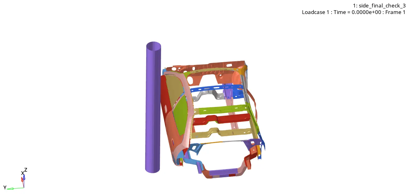
The next process of model setup is to create a Rigid wall. In this case, unlike the plane rectangular wall for the frontal crash case, we use a Rigid pole for our analysis. The Rigid pole is in the form of Infinite cylinder with a certain diameter. The diameter is determined by looking up Side crash standards which specifies the value of pole diameter to be 10 inches/254mm.
For defining the rigid pole, we have to define the origin and the normal direction. The coordinates are 2200, 1100, 1000 and 0, 0, 1000 respectively. The wall is placed beside the B-pillar of the car on the left side.
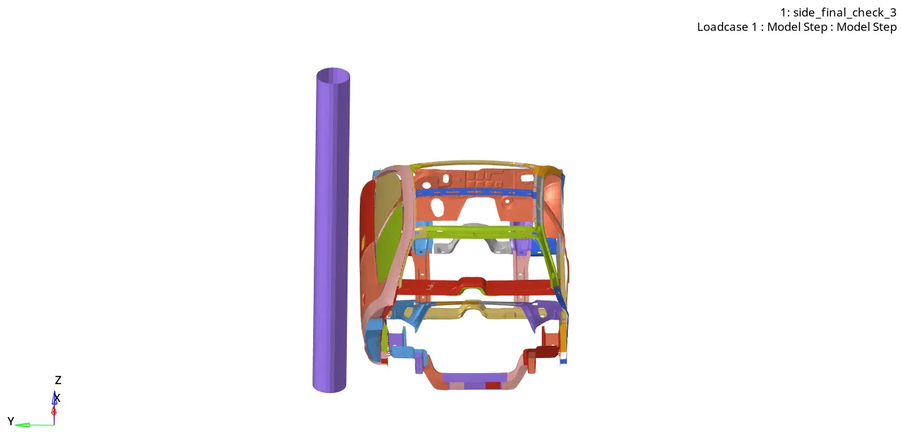
Followed by this, we define the contact interface necessary for the interactions inside the model. We use the Type 7 contact for this model which indicates Node to surface contact. There are few contacts which were defined prior for other analysis purposes which are not required for us and hence we delete them. Since it's a self-impact case, the master surface and the slave nodes are one and the same (the whole car model). The recommended parameters' values are entered which are shown below.
Igap=2, Gapmin=0.5, Inacti=6, Istf=4, Stmin=1kN/mm, Idel=2, Fric=0.2 and Iform=2.
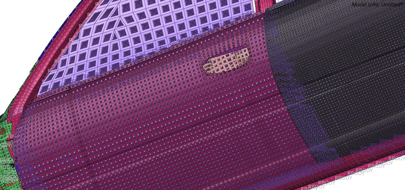
The small shapes deployed on each element shows the contact group that has been created. Followed by contact definition, we proceed to add mass to the model to achieve the target mass of 700kg. When the model is opened, the mass of the model is 166.3kg. The COG (Center of Gravity) of the model is located somewhere closer to the front seat of the car above the cross member.
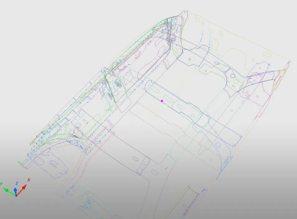
The pink coloured dot indicates the COG of the model. It should be moved with the help of masses in such a way that it is in the right position. This helps solve the issue of wrong COG location and also achieving the target mass. We add masses in four different locations to obtain a satisfactory mass in the required regions making it easier for simulations. The masses are:
Tank region = 50kg.
Frontal region = 240kg.
Rear region = 160kg.
Base = 84kg.
The mass in the base is added to achieve the target mass and with this, the target mass of 700kg is achieved. After mass addition, we need to give the initial velocity condition for the model which is defined by the command INIVEL. All the nodes of the model are selected and the value of velocity 35mph or 15.65mm/ms is given in the global Y-direction where the pole is located.
After defining the initial velocity, we open the Penetration checker. We check for the Type 7 contact group, the elements and also the components. 0 collisions are reported which means our model is free of penetrations and intersections. With this the model setup is complete and we proceed to output extraction.
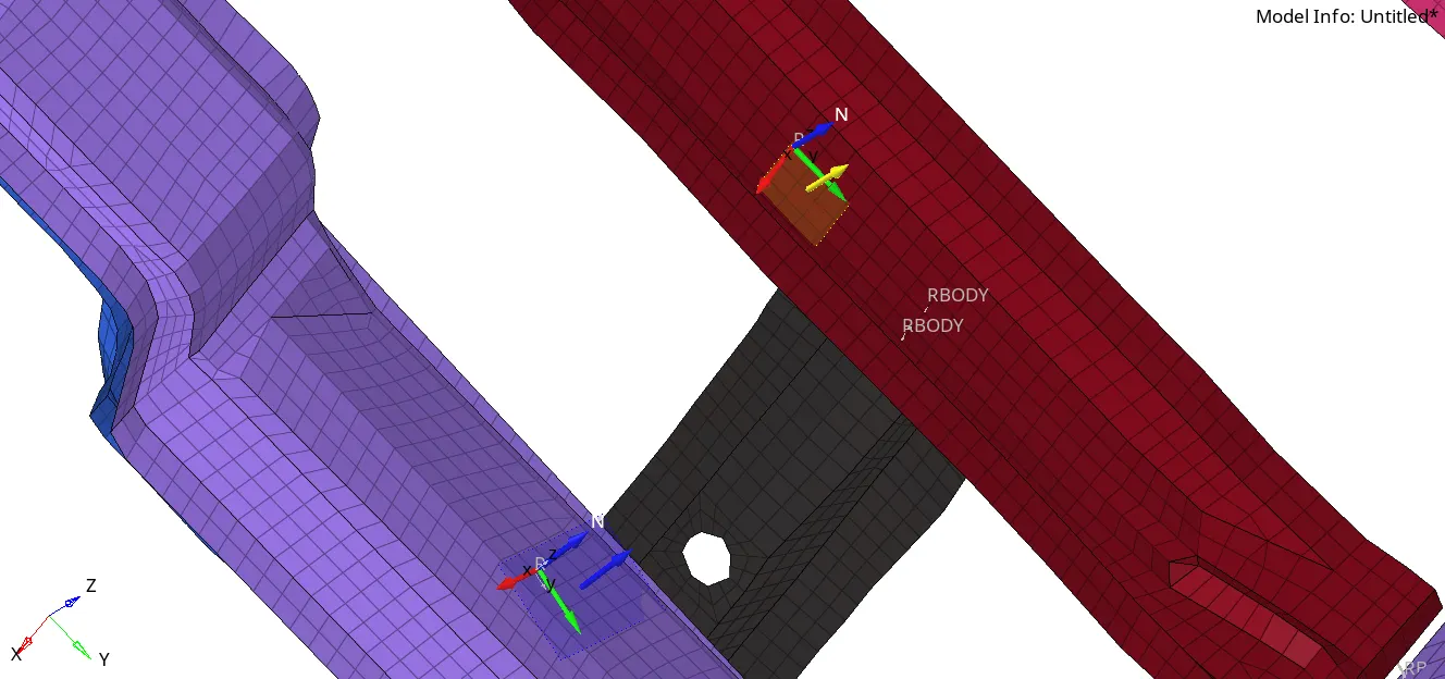
Before outputs can be extracted we need to set up the model to obtain the results. We can start with the forces extraction. For getting forces, we create a section on both the cross members. N1, N2 and N3 are defined and the moving frame is also defined and its value entered for the section as the frame of reference.
Followed by this, we set up the requirements for intrusions. We are requested to find the intrusions due to the crash in three different regions.
1. B-pillar rocker
2. Hinge pillar
3. Fuel tank
All these three nodal locations are located on the side frame closer to the base of the model. To observe the intrusions on the nodes we take the time history (for output) of the nodes and also create a moving skew on the other side of the model in the same location and the id is entered for the frame_id for the TH of the node. This is done because we try to measure the displacement of the node with respect to the skew present on the opposite side so that it can be plotted and the intrusion observed.
The final output request belongs to a node for which we are expected to find the peak velocity of a node located on the inner side of the left front door. Followed by this, we create a time history (TH) file for every single output parameters.
One additional aspect of this model compared to the previous frontal crash is that we have added PLAS_BRIT (which expands to plastic brittle material) for the glass window to obtain a shattering effect of the glass. This is done by changing the material card for the front and back glass window. The glass used in car window application is called Laminated Glass with the chemical name Polyvinyl Butryl (PVB). The glass is different from other common glasses as it does not shatter completely on impact but rather gets dented and cracked.
The properties of this laminated glass are obtained after quick research and they are given for the material card.
With this, we have completed setting up the model and proceed to output extraction.
OUTPUT EXTRACTION AND ANALYSIS
We start by observing the simulation time.
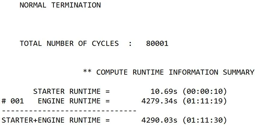
We can observe that we got normal termination and the simulation has run for 1 hour and 11 minutes with total number of cycles at 80001.
Then we take a look at the mass error and energy error.
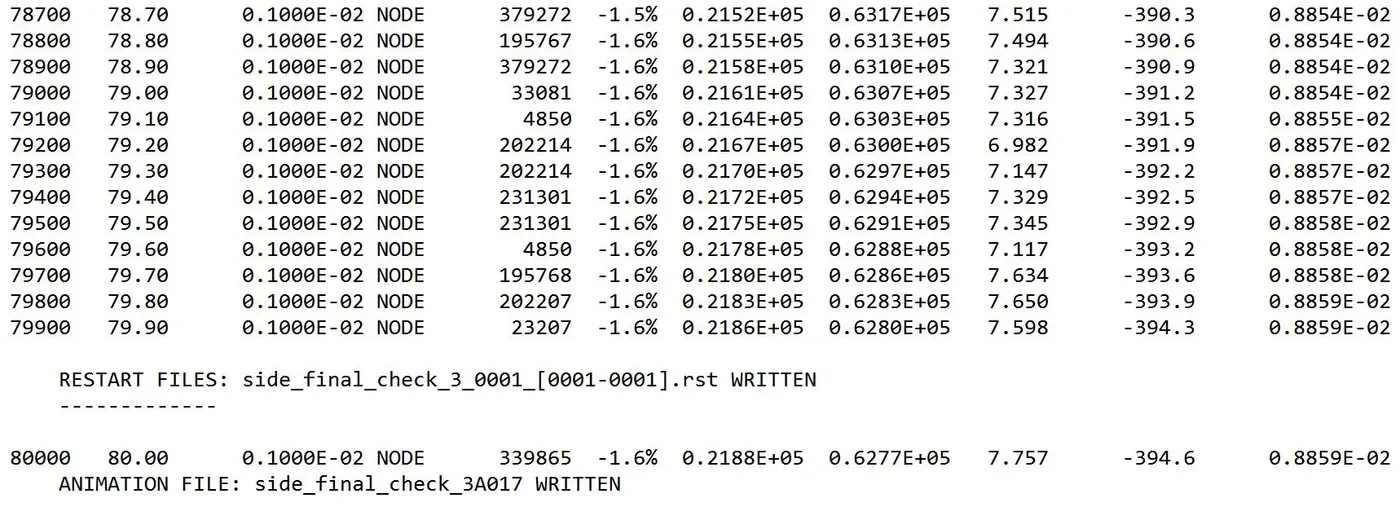
The Energy error is at -1.6% and the mass error is 0.0088kg. Both these values fall under the optimal category and hence the model is a good one. After this, we analyse the plots using HyperGraph 2D. The file that contains the plots is named as T01 file which corresponds to time history (TH) file. WE start by taking a look at the Energies of the system.
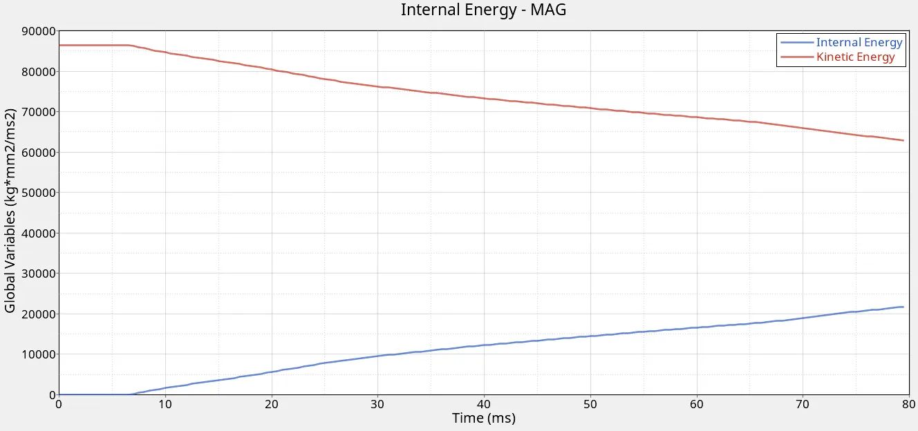
The value of Kinetic Energy starts from 86500 kg*mm^2/ms^2 and reduces gradually and the value of Internal Energy increases from 0 to a maximum of 21750 kg*mm^2/ms^2 before the simulation ends. Followed by this, we take a look at the Total Translational Energy (TTE) and Contact Energy along with Hourglass Energy to get a clear idea of how the energy is dissipated.
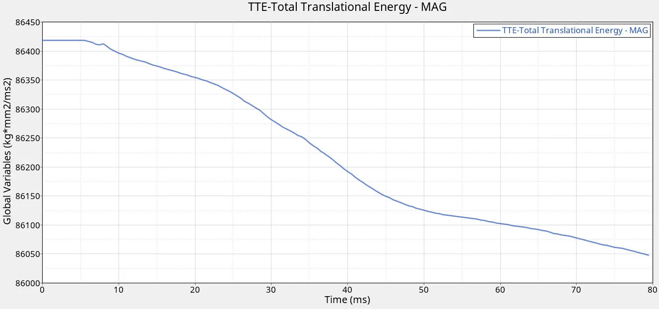
The Translational energy is slightly lesser than the Kinetic ENergy at 86440 kg*mm^2/ms^2 and gradually decreases over time until the end of the simulation.
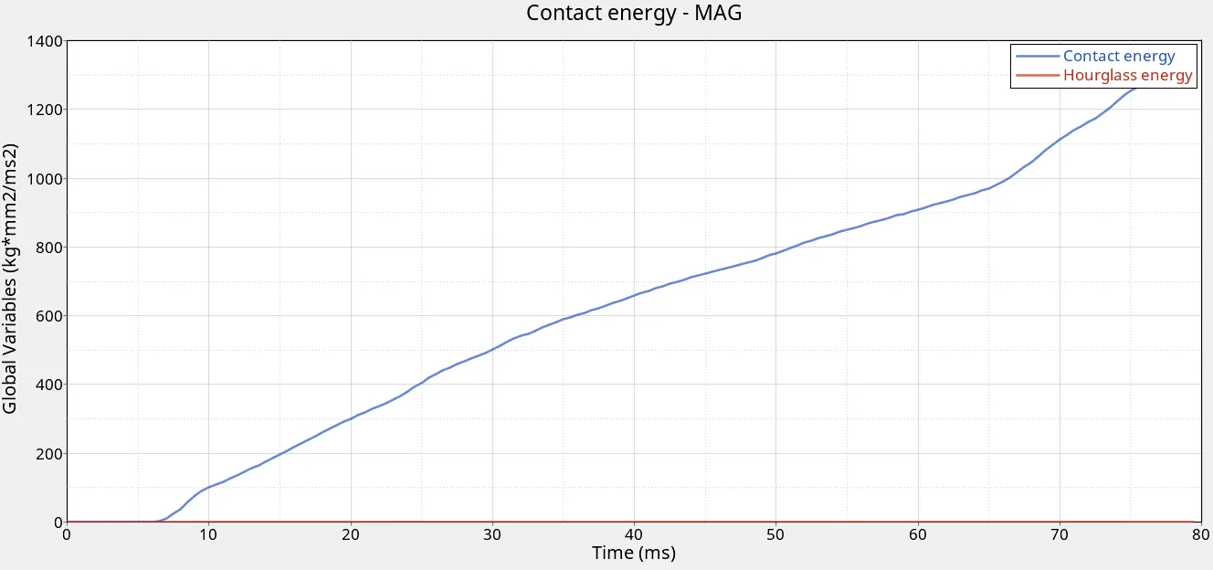
The contact energy keeps increasing after starting from zero because of the impact against the pole but the value of Hourglass energy remains zero which is a good sign as this indicates no presence of artificial energy generation and this can be attributed to QEPH formulation. With this, the Energy analysis is complete and it is followed by Sectional forces analysis.
The cross member forces are to be analysed here. As we can observe from one of the pictures shown earlier depicting the cross member along with the moving frame, the Y-axis is along the beam and hence we take forces along that direction as it is affected the most due to impact rather than the resultant Normal/Tangential force which does not have much significance in this scenario.
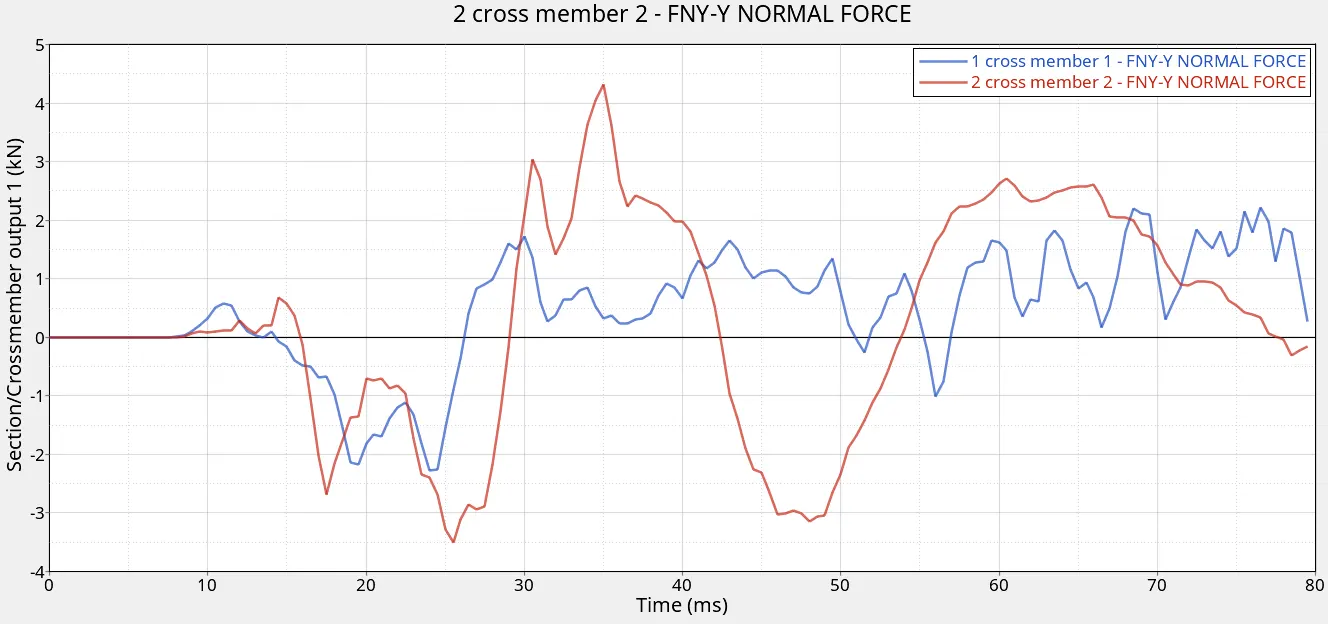
The red line indicates the cross member attached to the B-pillar rocker and the blue line indicates the other cross member. The maximum value of force for the first member is 2.21kN and for the second cross-member is 4.31kN. As we can observe from the curve, the first beam experiences less impact compared to the second member. This can be attributed to the fact that the second member is attached to the B-pillar which is in direct line of impact and hence experiences more force.
The Rigid wall/pole forces are also plotted below.
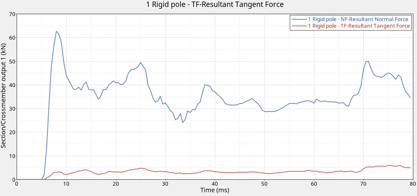
The maximum value of Tangential force is 5.98kN and the maximum value of the Resultant Normal force is 62.7kN.
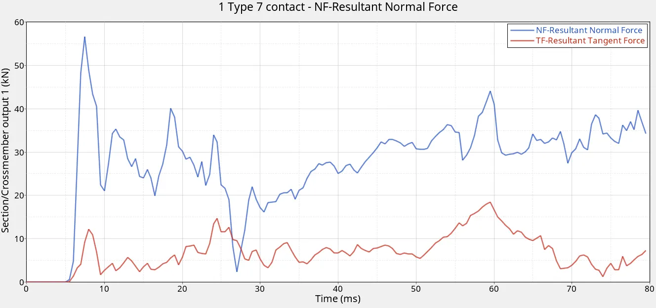
The Contact forces are also plotted as we select the Type 7 and plot the resultant Normal and Tangential forces.
This concludes all the force plots and we check the intrusions now.
We start by plotting the intrusions for the B-pillar rocker. We take the displacement along the Z-direction because the moving skew we have defined locally for reference has z-axis along the impact direction.
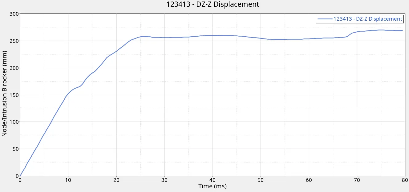
The node on the B-pillar has moved by 270mm which means it has affected the passenger present on the side of impact as it has moved by a significant distance because the distance from the node to the center of the model is close to 570mm. Now, we take a look at the intrusion in fuel tank region.
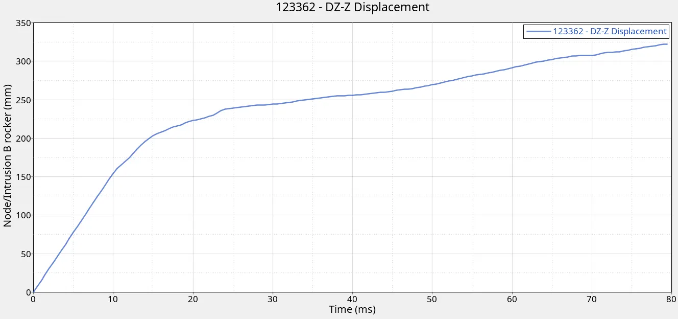
The maximum displacement value is 322mm which means it has moved more than the first case and the fuel tank will be affected and damaged in a bad way.
In order to reduce the impact on the fuel tank for having less intrusion, we can add more deformable material to the material that can absorb more energy so that it's not translated to the fuel tank regio. Moreover, additional reinforcements can be added in the region to make it more strong so that fuel tank prevails in an accident occurence scenario.
The final intrusion analysis is in the hinge pillar region.
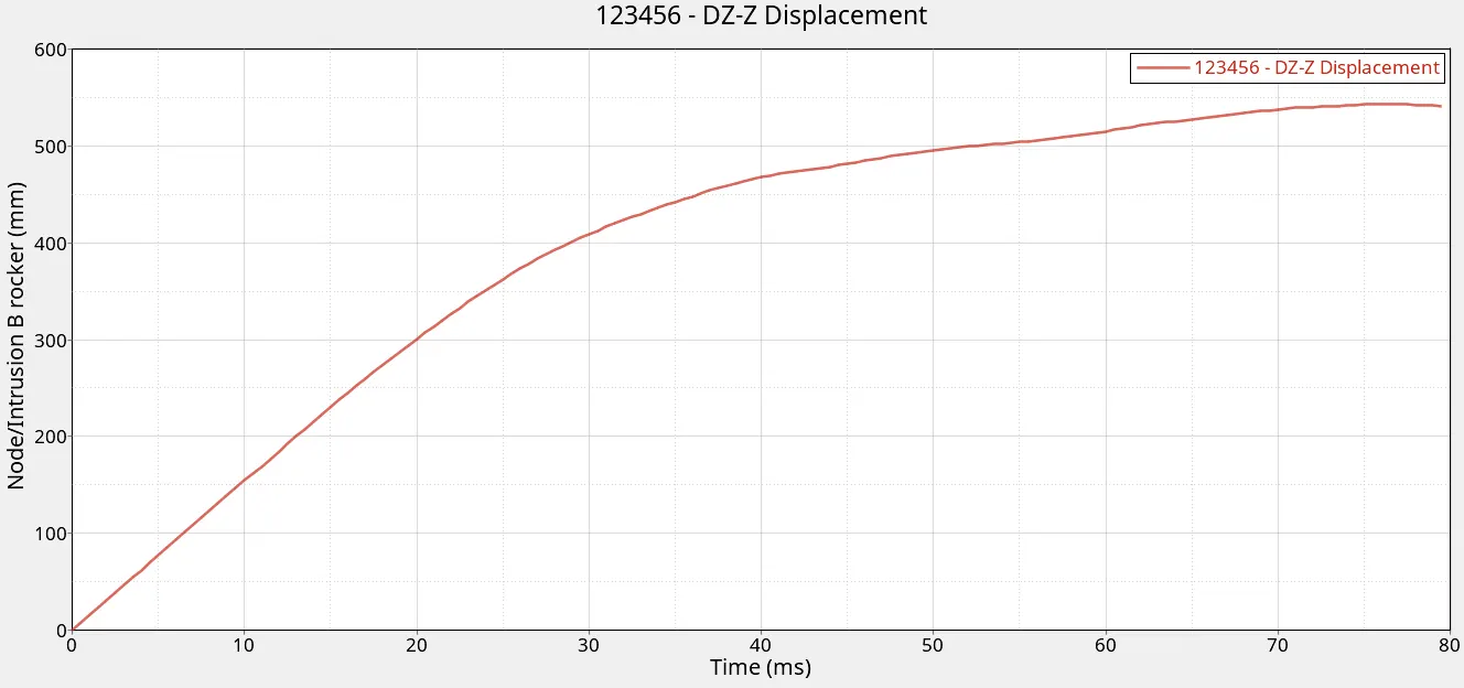
The value of intrusion here is 543mm which means that this region is affected the most out of all the regions in which we have obtained the results. This value indicates that the intrusion here is closer to midway of the car which is not good for a vehicle designed for safe passage of travellers.
With this, the intrusion analysis is complete and we take a look at the peak velocity of the node that is requested.
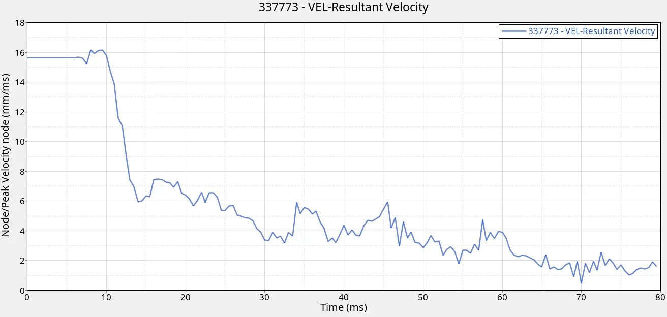
The peak velocity is requested and hence we plot the resultant velocity. The peak velocity of the node is 16.14mm/ms or 36.1mph which is higher than the initial velocity. This occurs at the moment right after the impact which can be the reason for the higher value. With this our analysis of this simulation is complete.
Finally, we have attached the animation video of the simulation for visualisation purposes.
OBSERVATIONS AND CONCLUSION
From the analysis for Side Crashworthiness, we can say that it is a vital part of developing a car in the industry as it needs to follow the safety protocol as well as ensure the safety of the passengers. We need to understand that there are several factors going in before the final finished product is ready. In this, the crashworthiness analysis is one important aspect. For the purpose of this analysis, we have to undergo certain procedures to set up the model to satisfy the requirements. We observe the forces experienced, the velocity and also the Energy transfer in this analysis.
We can conclude that all these parameters are an effective means to analyse the crashing simulation which is performed to mitigate the risks when an accident occurs in a real-life scenario.