Selection of spring and anti-roll bar for a 4WD-Sedan
Introduction
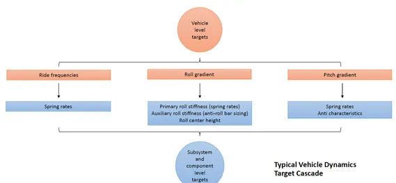
The project focuses on the selection of springs and anti-roll bars for a 4WD sedan with Mcpherson strut in the front and Multi-link suspension in the rear while staying with in the vehicle level targets.
Initially ride frequency ,spring rates are calculated then calculations of roll gradient, primary roll stiffness e.t.c, final stage is the pitch analysis of the vehicle. All the stages are interrelated and it is an iterative process followed through out the project.
Typical Vehicle Dynamics Target Cascade
Selection of springs
5% of deviation in targets are allowed.
Front Ride frequency vehicle level target is 1.35+- 5%Hz.
Ride frequency is given by
fs=2⋅πKrMs">fs=2⋅π√KrMsfs=2⋅πKrMs
Ride frequency of typical vehicles are
For passenger cars, ride frequency range is 0.5-1.5Hz.
For sedan race cars and for moderate downforce race cars, ride frequency range is 1.5-2.0Hz.
For high downforce race cars, 3.0-5.0+Hz.
From this it is evident that we are working for a passenger car.
We have chosen a front ride frequency of 1.38Hz. What if the car have ride frequency at both rear and front same. Below graph show a similar condition while moving over a bump.
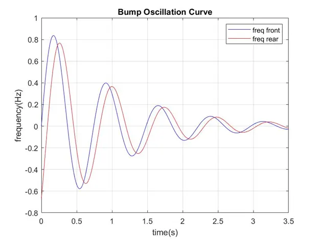
Wheelbase has a greater effect in the behavior of the front and rear wheels, so we should consider the time taken by the wheelbase too which can be calculated by,
twb(s)=Wheelbasespeed">twb(s)=Wheelbasespeedtwb(s)=Wheelbasespeed
twb=0.086sec
Rear ride frequency is computed using the formula,
f(rear)=1(1f(ont)-twb)">f(rear)=1(1f(ont)−twb)f(rear)=1(1f(ont)-twb)
f(rear)=1.57Hz
We use a matlab code to plot the bump oscillation profile of the vehicle moving at a speed of 65mph,
%bump oscillation curve plot
t_wb=0.086;%time lag between the rear and front end due to wheel base
freq_front=1.38;%Hz
freq_rear=1.57;%Hz
time=[0:0.01:3.5];
i=1;
for t=0:0.01:3.5;
front_amp(i)=exp(-t)*sin(2*pi*freq_front*t);
rear_amp(i)=exp(-t)*sin(2*pi*freq_rear*(t-t_wb));
i=i+1;
end
figure();
plot(time,front_amp,'b');
hold
plot(time,rear_amp,'r');
xlabel('time(s)')
ylabel('frequency(Hz)');
title('Bump Oscillation Curve');
legend('freq front','freq rear');
grid on;
hold off;
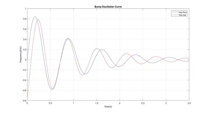
It can be inferred from the plot that at 0.7 sec the rear ride frequency catches up with the front ride frequency. Usually after 1 sec damper comes in to play.
Springs
Spring rate obtained are:
At front
At rear
ks=KwMR2">ks=KwMR2ks=KwMR2
Kw = wheel rate (lb/in)
MR = motion ratio usually less than 1
Kw=Kt⋅KrKt-Kr">Kw=Kt⋅KrKt−KrKw=Kt⋅KrKt-Kr
Kr = Ride rate (lb/in)
Kr=4π2f2Msprung386.4">Kr=4π2f2Msprung386.4Kr=4π2f2Msprung386.4
Selection of anti roll bar
When the vehicle is negotiating a turn or when one wheel of the vehicle hits a bump, the weight tends to transfer in the lateral direction, due to this the body tends to roll. With the help of Roll bars, this can be minimised.
For selecting the anti-roll bar, first the roll stiffness due to the selected springs (primary stiffness) were calculated. Using the target roll gradient, the auxiliary roll stiffness (Roll stiffness due to Anti-Roll bar) of front and rear were calculated.
First, the distance between CG and the axles were calculated. Then the moment arm was calculated using the formula indicated below.
harm=hs−(ZRCf.bs+ZRCr.as)L
hs is the sprung mass CG height (in)
ZRCf and ZRCr are the height of front and rear roll centres respectively (in)
as and bs are the distance between CG and axles (front and rear) (in)
With the help of target roll gradient, the required roll moment was calculated.
Here the target roll gradient is 3.8°/g±5%
choosen roll gradient is 3.8deg/g
MϕAy=Ws⋅harm12⋅(1+(ϕAy⋅π180))
Mϕ/Ay is the Roll moment (ft-lb/g)
Ws is the sprung mass weight (lb)
harm is the length of the moment arm (in)
ϕ/ Ay is the Roll gradient (deg/g)
The total roll stiffness (ft-lb/deg) was calculated using Roll moment and the target roll gradient.
Kϕ=MϕAy⋅AyϕAs
a next step, the roll stiffness (ft-lb/deg) due to tire and wheel rate were computed using the formula (for both front and rear axle),
Kϕtirea=Ktirea⋅t21375">Kϕtirea=Ktirea⋅t21375Kϕtirea=Ktirea⋅t21375
Kϕwra=Kwra⋅t21375">Kϕwra=Kwra⋅t21375Kϕwra=Kwra⋅t21375
Where,
t is the track width (in)
Ktirea is the stiffness of the tire for a particular axle (lb/in)
Kwra is the wheel rate for a particular axle (lb/in)
‘a’ represents axle (it can be front or rear)
Then, the Total load transfer (TLT in lb/g) was found,
TLT=Wt⋅hs/t
Where,
Wt is the total weight of the vehicle (lb)
hs is the CG height (in)
t is the track width (in)
Then, the Total Load transfer in the front (lb/g) was determined. In order to get under steer effect, the load at front is set to be 5% greater than the rear.
TLTF=TLT*(Weightdistribution%+5%)
Since our major concern is to compute the total front roll stiffness (ft-lb/deg) due to lateral load transfer, load transfer due to sprung and unsprung masses can be subtracted.
Kϕtf=TLTF−LTusf−LTsf⋅(t12)ϕ
Load transfer due to unsprung mass (lb/g) is given by,
LTusf=(Wusf⋅Rt)/t Where,
Rt is the Loaded radius of the tireLoad transfer due to sprung mass (lb/g) is given by,
LTsf=(Wsf⋅ZRCf)/(t)
Total roll stiffness in the rear (ft-lb/deg) is given by,Kϕtr=Kϕ−Kϕtf
In order to find the roll stiffness of Anti-roll bar, first we need to isolate the effect of tire, by using the formula,
Kϕwca=(Kϕtirea⋅Kϕta)/(Kϕtirea−Kϕta)
Where,
Kϕwca is the roll stiffness at wheel centre level for a particular axle (ft-lb/deg)
Kϕtirea is the roll stiffness due to the tire for a particular axle (ft-lb/deg)
Kϕta is the total roll stiffness for a particular axle (ft-lb/deg)
Springs and anti-roll bars are connected in parallel, which is connected with the tire in series. Refer the free body diagram below.
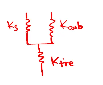
Roll stiffness due to Roll bar (ft-lb/deg) can be computed by,
Kϕarba=Kϕwca−Kϕwra
Roll stiffness due to Roll bar (in-lb/deg) is given by,
Kϕarba⋅12
Roll rate due to Auxiliary bar (Anti-roll bar) in lb/in,
Karba=Kϕarba⋅180πMR2⋅t2
Max. allowed front auxiliary roll stiffness is 60%.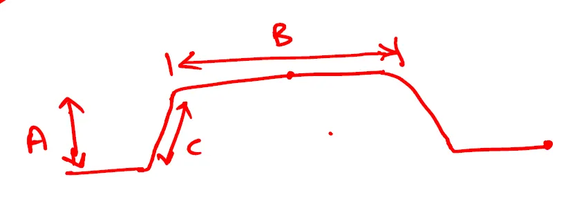
Calculation for Outer Diameter of Anti Roll bar,Assumption,Inner diameter is zeroMaterial of the Anti-roll bar is steel
Outer diameter in inches
OD=4√Karba⋅((0.4422⋅A2⋅B)+(0.2264⋅C3))5⋅105
outer diameter in mm = Outer diameter in inches * 25.4
Outer diameter of Anti roll barFront – 22.12mm ~ 22.25mm Rear – 12.12mm ~ 12.25mm
Optimization of pitch gradients
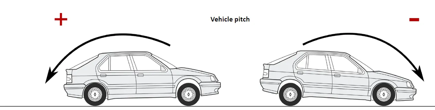
Pitch is caused by longitudinal load transfer.
Dive: Causes the rear wheels to lift during braking.
Squat: Cause the front wheels to lift during braking.
Longitudinal load transfer:
ΔW=W⋅hsl">ΔW=W⋅hslΔW=W⋅hsl
W = total weight of the vehicle(lb)
hs = distance of CG from the ground(in)
l = wheelbase(in)
After which deflection of the spring are calculated
Z=(ΔWKs)">Z=(ΔWKs)Z=(ΔWKs) in inches
Pitch gradient is given by
ϕ=tan-1(Zf+Zrl)⋅180π">ϕ=tan−1(Zf+Zrl)⋅180πϕ=tan-1(Zf+Zrl)⋅180π in deg/g
For swing arm horizontal distance, 70 to 120 inches is a reasonable starting point.
e = vertical distance from the centre of contact patch to the IC
d = horizontal distance from center of contact patch to IC
Braking pitch gradient
During braking load transfer is taking place at front,
Anti dive angle = tan-1(efdf)⋅180π">tan−1(efdf)⋅180πtan-1(efdf)⋅180π
Anti lift angle = tan-1(erdr)⋅180π">tan−1(erdr)⋅180πtan-1(erdr)⋅180π
Ideal anti lift angle and Ideal anti dive angle = tan-1(hsl)⋅180π">tan−1(hsl)⋅180πtan-1(hsl)⋅180π
%Anti dive = (Anti dive angle/Ideal anti dive angle)*100
%Anti lift = (Anti lift angle/Ideal anti lift angle)*100
deflection with compensation(Zwcf,Zwcr) = Z*(100-% Anti)/100
pitch gradient with compensation(Φc) = atan((Zpcf+Zpcr)/L)*180/π
Target braking pitch gradient is 1deg/g
Braking pitch gradient got is 1.08deg/g
Acceleration pitch gradient
During acceleration load transfer is taking place at rear,
Anti squat angle = tan-1(er-Rldr)⋅180π">tan−1(er−Rldr)⋅180πtan-1(er-Rldr)⋅180π
Anti lift angle = tan-1(ef-Rldr)⋅180π">tan−1(ef−Rldr)⋅180πtan-1(ef-Rldr)⋅180π
Ideal anti lift angle and Ideal anti dive angle = tan-1(hsl)⋅180π">tan−1(hsl)⋅180πtan-1(hsl)⋅180π
%Anti squat = (Anti squat angle/Ideal anti dive angle)*100
%Anti lift = (Anti lift angle/Ideal anti lift angle)*100
deflection with compensation(Zwcf,Zwcr) = Z*(100-% Anti)/100
pitch gradient with compensation(Φc) = atan((Zpcf+Zpcr)/L)*180/π
Target acceleration pitch gradient is 2deg/g
Acceleration pitch gradient got is 2.02deg/g
Conclusion
The springs and anti-roll bars were selected for a 4WD Sedan with a McPherson strut suspensionin the front and a multilink setup in the rear using the specified vehicle level targets (ride frequency, roll gradient and pitch gradient). The targets were maintained well within the limits and the values are tabulated below.
Spring rate and Roll bar dimension
Parameter unit Front Rear
Spring rate lb/in 208.25 288.29
OD of roll bar in 0.87 0.83
|
Target |
units |
value |
Max |
Min |
obtained value |
|
Allowable deviation |
5% |
||||
|
Front Ride frequency |
Hz |
1.35 |
1.4175 |
1.2825 |
1.38 |
|
Roll gradient |
deg/g |
3.8 |
3.99 |
3.61 |
3.8 |
|
Braking pitch gradient |
deg/g |
2 |
2.1 |
1.9 |
2.02 |
|
Acceleration pitch gradient |
deg/g |
1 |
1.05 |
0.95 |
1.08 |
|
Max.allowed front auxialry roll stiffness |
% |
60 |
47.2 |
||
|
Max.allowed rear auxilary roll stiffness |
% |
30 |
11.8 |
Link to the excel sheet is given below
https://drive.google.com/file/d/1KXftGJFVOPCyqZjtqMgGsxGqPQOcRBdC/view?usp=sharing
Reference:
W. F. Milliken and D. L. Milliken, Race Car Vehicle Dynamics.Warrendale, PA, USA: SAE, 1995.