Section Modulus calculation and optimization
SECTION MODULUS CALCULATION AND OPTIMIZATION :
Objective:
The main objective of this project is to learn the basic tools, commands, and the calculation and optimization of the Section Modulus using Siemens NX CAD. The objectives of this project are as follows:
-
To understand and learn the basic Graphical User Interface (GUI) of Siemens NX CAD
-
To understand and learn the Calculation and Optimization of Section Modulus of Hood Design Using Siemens NX CAD.
What is section modulus:
Section modulus is a geometric property for a given cross-section used in the design of beams or flexural members. Other geometric properties used in the design include an area for tension and shear, the radius of gyration for compression, and the moment of inertia, and polar moment of inertia for stiffness.
Types of section modulus.
-
Elastic section modulus(S).
-
Plastic section modulus(Z).ELASTIC MODULUS SECTION
Elastic section modulus :
The elastic section modulus is defined as the ratio of the second moment of area (or moment of inertia) and the distance from the neutral axis to any given (or extreme) fiber. It can also be defined in terms of the first moment of area.
Significance
It is also often used to determine the extreme fiber elastic stresses as well as the yield moment (My) of elastic sections such that My=S×σy, where σy is the yield strength of the material. It is a commonly used property in the design of flexural members of steel, post-tensioned concrete, and timber sections.
| Cross-sectional shape | Figure | Equation | Comment |
|---|---|---|---|
| Rectangle | {\displaystyle S={\cfrac {bh^{2}}{6}}} |
Solid arrow represents neutral axis | |
| doubly symmetric I-section (major axis) | {\displaystyle Sx={\cfrac {BH^{2}}{6}}-{\cfrac {bh^{3}}{6H}}}
{\displaystyle Sx={\tfrac {Ix}{y}}} with {\displaystyle y={\cfrac {H}{2}}} |
NA indicates neutral axis | |
| doubly symmetric I-section (minor axis) | {\displaystyle Sy={\cfrac {B^{2}(H-h)}{6}}+{\cfrac {(B-b)^{3}h}{6B}}} [4] [4] |
NA indicates neutral axis | |
| Circle | {\displaystyle S={\cfrac {\pi d^{3}}{32}}} [3] [3] |
Solid arrow represents neutral axis | |
| Circular hollow section | {\displaystyle S={\cfrac {\pi \left(r_{2}^{4}-r_{1}^{4}\right)}{4r_{2}}}={\cfrac {\pi (d_{2}^{4}-d_{1}^{4})}{32d_{2}}}} |
Solid arrow represents neutral axis | |
| Rectangular hollow section | {\displaystyle S={\cfrac {BH^{2}}{6}}-{\cfrac {bh^{3}}{6H}}} |
NA indicates neutral axis | |
| Diamond | {\displaystyle S={\cfrac {BH^{2}}{24}}} |
NA indicates neutral axis | |
| C-channel | {\displaystyle S={\cfrac {BH^{2}}{6}}-{\cfrac {bh^{3}}{6H}}} |
NA indicates neutral axis |
 ,
,
Plastic section modulus:
The plastic section modulus is used for materials where elastic yielding is acceptable and plastic behavior is assumed to be an acceptable limit. Designs generally strive to ultimately remain below the plastic limit to avoid permanent deformations, often comparing the plastic capacity against amplified forces or stresses.
The plastic section modulus depends on the location of the plastic neutral axis (PNA). The PNA is defined as the axis that splits the cross section such that the compression force from the area in compression equals the tension force from the area in tension. So, for sections with constant yielding stress, the area above and below the PNA will be equal, but for composite sections, this is not necessarily the case.
The plastic section modulus is the sum of the areas of the cross section on each side of the PNA (which may or may not be equal) multiplied by the distance from the local centroids of the two areas to the PNA: Zp = Acyc + Atyt
| Description | Figure | Equation | Comment |
|---|---|---|---|
| Rectangular section | {\displaystyle Z_{P}={\cfrac {bh^{2}}{4}}} [5][6] [5][6] |
{\displaystyle A_{C}=A_{T}={\cfrac {bh}{2}}} , {\displaystyle y_{C}=y_{T}={\cfrac {h}{4}}} , {\displaystyle y_{C}=y_{T}={\cfrac {h}{4}}} |
|
| Rectangular hollow section | {\displaystyle Z_{P}={\cfrac {bh^{2}}{4}}-(b-2t)\left({\cfrac {h}{2}}-t\right)^{2}} |
where: b=width, h=height, t=wall thickness | |
| For the two flanges of an I-beam with the web excluded[7] | {\displaystyle Z_{P}=b_{1}t_{1}y_{1}+b_{2}t_{2}y_{2}\,} |
where:
{\displaystyle b_{1},b_{2}} |
|
| For an I Beam including the web | {\displaystyle Z_{P}=bt_{f}(d-t_{f})+0.25t_{w}(d-2t_{f})^{2}} |
[8] | |
| For an I Beam (weak axis) | {\displaystyle Z_{P}=(b^{2}t_{f})/2+0.25t_{w}^{2}(d-2t_{f})} |
d = Full height of the I Beam | |
| Solid Circle | {\displaystyle Z_{P}={\cfrac {d^{3}}{6}}} |
||
| Circular hollow section | {\displaystyle Z_{P}={\cfrac {d_{2}^{3}-d_{1}^{3}}{6}}} |
 =width, {\displaystyle t_{1},t_{2}}
 =thickness, {\displaystyle y_{1},y_{2}}
 are the distances from the neutral axis to the centroids of the flanges respectively.
The plastic section modulus is used to calculate the plastic moment, Mp, or full capacity of a cross-section. The two terms are related by the yield strength of the material in question, Fy, by Mp=Fy*Z. Plastic section modulus and elastic section modulus are related by a shape factor which can be denoted by 'k', used for an indication of capacity beyond elastic limit of material. This could be shown mathematically with the formula .
K = (Z/S)
SECTION MODULUS CALCULATON AND OPTIMIZATION :
Hood Main Design, first case:
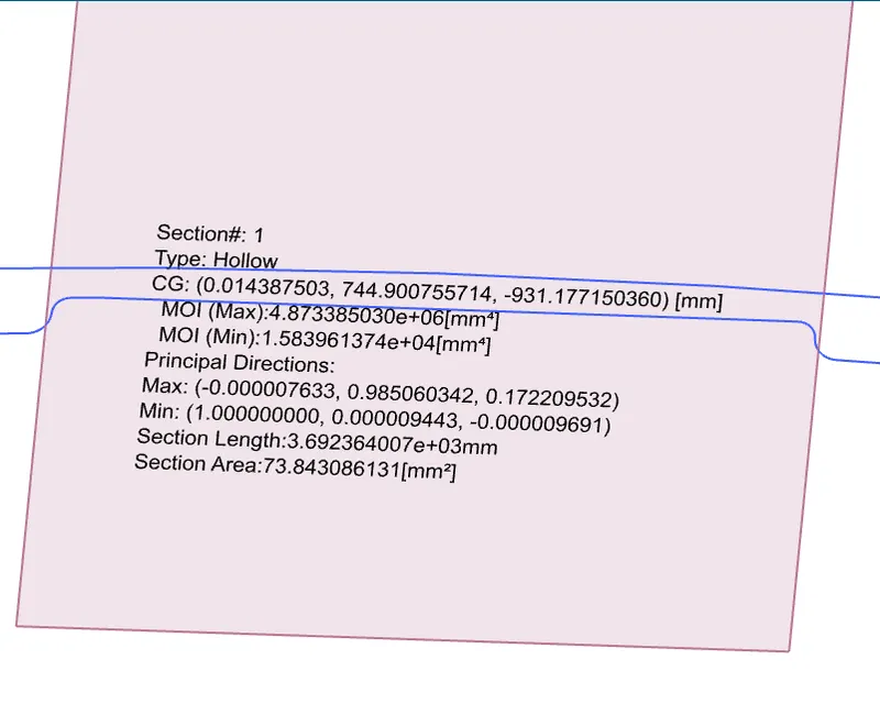
Calculation of Section Modulus of main Hood:
S = section modulus.
I = moment of inertia.
Y = Distance between the neutral axis and the extreme end of the object.
S = ?
I (min) = 1.583961374 x 10^4 [mm^4]
Y = 881.898568 / 2
Y = 440.9492
FORMULA,
S=I/Y
Moment of Inertia (MOI), Imin = 1.58396137 * 10^4[mm^4]
=15839.6137 / 440.949[mm]
=35.92164[mm^3]
Moment of Inertia (MOI), Imax = 4.873385030 * 10^6[mm^4]
= 4873385.03 / 440.949 [mm]
= 11052.03783 [mm^3]
SECOND CASE,
HOOD INNER PANEL OFFSETTED 5 MM TO DOWNWARDS.
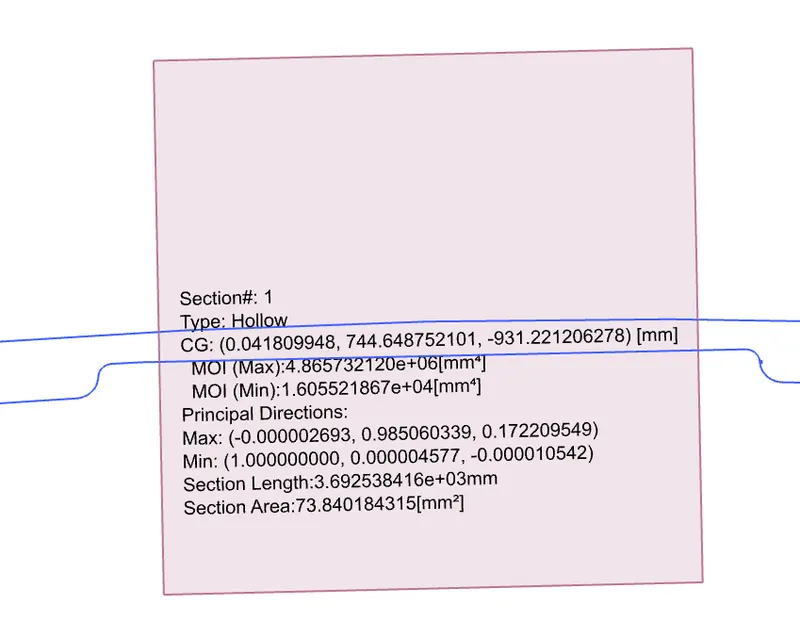
Moment of Inertia (MOI), Imin = 1.605521867 * 10^4[mm^4]
= 16055.21867 /440.949[mm]
= 36.410602[mm^3]
Moment of Inertia (MOI), Imax = 4.865732120 * 10^6[mm^4]
= 4865732.12 / 440.949[mm]
= 11034.68228[mm^3]
Conclusion:
Thus, the section modulus of the Front Hood of a car was calculated and compared with the optimized hood and found the better result.
second case optimized hood resulted in the increased strength.