Section Modulus calculation and optimization
Section Modulus calculation and optimization of hood
Section modulus is a geometric property for a given cross-section used in the design of beams or flexural members. Other geometric properties used in design include area for tension and shear, radius of gyration for compression, and moment of inertia and polar moment of inertia for stiffness. Any relationship between these properties is highly dependent on the shape in question. Equations for the section moduli of common shapes are given below.
There are two types of section modulus,
1.The elastic section modulus,
- The plastic section modulus
For general design, the elastic section modulus is used, applicable up to the yield point for most metals and other common materials
Elastic section modulus S = I/y,
Where,
S = Elastic Section Modulus
I = Moment of Inertia
y = distance between the neutral axis and the extreme end of the object
Notation
North American and British/Australian convention reverse the usage of S & Z. Elastic modulus is S in North America, but Z in Britain/Australia, and vice versa for the plastic modulus. Eurocode 3 (EN 1993 - Steel Design) resolves this by using W for both, but distinguishes between them by the use of subscripts - Wel and Wpl.
Uses of Section modulus
Though generally section modulus is calculated for the extreme tensile or compressive fibres in a bending beam, often compression is the most critical case due to onset of flexural torsional (F/T) buckling. Generally (except for brittle materials like concrete) tensile extreme fibres have a higher allowable stress or capacity than compressive fibres.
There may also be a number of different critical cases that require consideration, such as there being different values for orthogonal and principal axes and in the case of unequal angle sections in the principal axes there is a section modulus for each corner.
For a conservative (safe) design, civil structural engineers are often concerned with the combination of the highest load (tensile or compressive) and lowest elastic section modulus for a given section station along a beam, although if the loading is well understood one can take advantage of different section modulus for tension and compression to get more out of the design. For aeronautical and space applications where designs must be much less conservative for weight saving, structural testing is often required to ensure safety as reliance on structural analysis alone is more difficult (and expensive) to justify.
Case 1
Calculation for the section modulus before optimization of hood
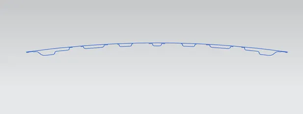
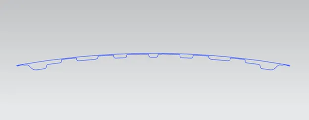
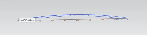
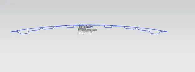
The 2D curve created by using intersection curve option, after creating the intersection curve it has an open curve. Created a sketch to close the curve. The closed curve is suitable for the section inertia analysis.
2D Curve of hood in open condition
2D Curve of hood in closed condition
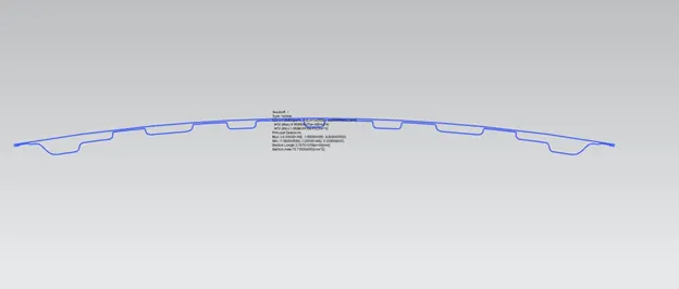
Section inertia analysis of hood
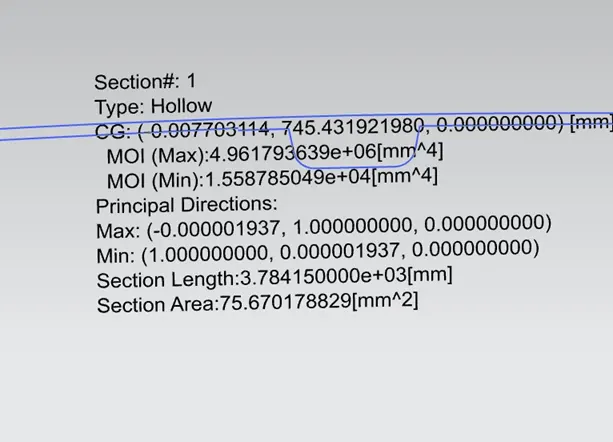
The minimum area moment of inertia for the hood is, I=15587.8504[mm^4]
To calculate y = The distance from the neutral axis to any given fibre/2
y= 876.94/2 = 438.47
Elastic section modulus S = I/y
S=15587.8504/438.47
S = 355.50[mm]^3
Case 2
Calculation for the section modulus After optimization of hood
Optimization in this case four emboss height increased 10mm to 12mm the results of moment of inertia as follows,
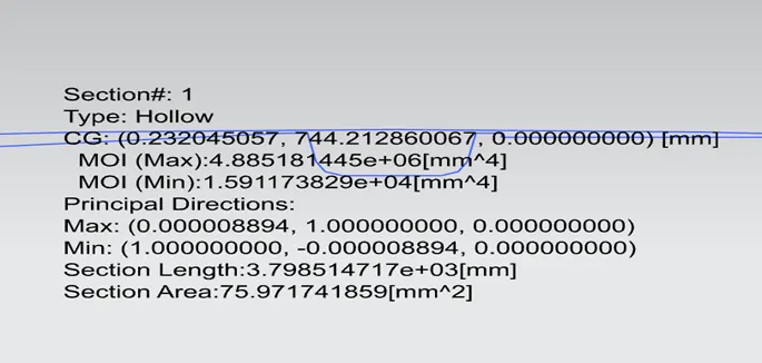
The minimum area moment of inertia for the hood is, I=15911.7382 [mm]^4
To calculate y = the distance from the neutral axis to any given fibre/2
y= 876.94/2 = 438.47
Elastic section modulus S = I/y
S= 15911.7382/438.47
S = 362.89[mm]^3
Conclusion
Comparing case1 and case2, case2 has higher sectional modulus. After the optimization of the embossed region on the inner panel of the hood, the section modulus of the hood is increased.