Section Modulus calculation and optimization
Section Modulus calculation and optimization
Aim:-
To calculate the section modulus by using the section of Hood desgin and then optimizing the hood panel for better section modulus.
Section modulus:
Section Modulus is the geometric property of the given cross-section of any shaft or beam structures. It is the direct measure of the strength of the shaft section or the beam section. Higher the section modulus of a structure, the more the resistive it becomes to bending.
S= I / Y
Section modulus is defined as the ratio of polar moment of inertia to the radius of the shaft or the distance from the neutral axis to the outer fibres.It is termed as the ratio of the second moment of inertia and distance from N.A (Neutral axis) to the extreme fiber. Also, it is the measure of the strength of a given member. The stress in the outermost section of the beam is computed with the help of section modulus. It is indicated by S.
Section modulus (Z)
Another property used in beam design is section modulus (Z).
The section modulus of the cross-sectional shape is of significant importance in designing beams. It is a direct measure of the strength of the beam. A beam that has a larger section modulus than another will be stronger and capable of supporting greater loads.
It includes the idea that most of the work in bending is being done by the extreme fibres of the beam, ie the top and bottom fibres of the section. The distance of the fibres from top to bottom is therefore built into the calculation.
The elastic modulus is denoted by Z. To calculate Z, the distance (y) to the extreme fibres from the centroid (or neutral axis) must be found as that is where the maximum stress could cause failure.
Section modulus is indicated as follows:
S = Section Modulus
I = Moment of Inertia
y = distance between the neutral axis and the extreme end of the object
Area moment of Inertia:
The area moment of inertia of a beams cross sectional area measures the beam ability to resist bending. The larger the moment of inertia less will be the bend.
Where,
M = Bending moment
I = Area moment of Inertia
E = Youngs modulus
R = Radius of gyration
Neutral axis: When beam is subjected to pure bending the top most fibres of the beam are subjected to maximum compression, while the bottom most fibres of the beams are subjected to maximum tension.
CASE 1 :- Before Optimization
The Hood which was already created is imported and the section inertia analysis is done.
We have to make sure that the curve obtained is a single/closed curve.
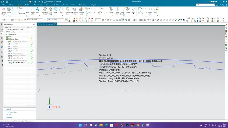
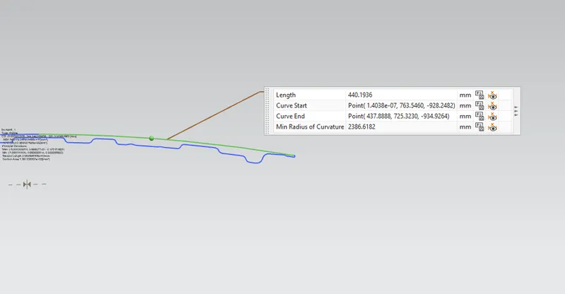
value of Y = 440.1936 mm
where ,
max MOI = 9.047669493e+07[mm^4]
min MOI = 2.564437484e+05[mm^4]
Formula of section modulus
S = I / Y
I = MOI ( min) value is considered
y = 440.1936 mm
Therfore , S = 2.564437484e+05 mm^4 / 440.1936 mm
= 58.2570369946 mm^3
CASE 2 : After modification
In order to increase the resistance to bending of HOOD, We have to make an improvement in section modulus of HOOD by 5 mm
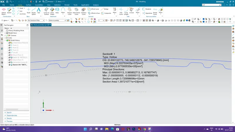
Maximum moment of inertia = 9.222793405e+07 [mm^4]
Minimum moment of inertia = 2.577000530e+05 [mm^4]
To find section modulus of new HOOD section, we have to calculate
S = I / Y
= 2.577000530e+05 mm^4 / 440.1936 mm
= 58.5424351 mm^3
Final result:
Thus the stiffness of the car hood has been increased by increasing its area moment of inertia.From the result we found out that increasing the cross-section area would give a better section modulus and helps in increasing the strength of the hood.