Section Modulus calculation and optimization
AIM: To calculate and compare the section modulus of the hood design and to conclude which one has a more strength.
INTRODUCTION OF SECTION MODULUS:
Section modulus is a geometric property for a given cross-section used in the design of beams or flexural members. Other geometric properties used in design include area for tension and shear, radius of gyration for compression, and moment of inertia and polar moment of inertia for stiffness. Any relationship between these properties is highly dependent on the shape in question. Equations for the section moduli of common shapes are given below.
There are two types of section moduli,
- Elastic section modulus
- Plastic section modulus
| Elastic section modulus |
Plastic section modulus |
|
|
Section Modulus Analysis:
Section modulus can be calculated using a formula
S = I/y
where,
S - Section modulus
I - Moment of Inertia
y - Distance from the neutral axis to the most extreme end of the object
CASE 1:-
- Take an intersection of the designed car hood outer panel and the inner panel
- Measure the moment of inertia by using the Inertia command in the CATIA v5 (I)
- Measure the length from the neutral axis to the one of extreem end (Y)
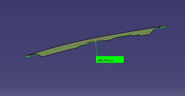
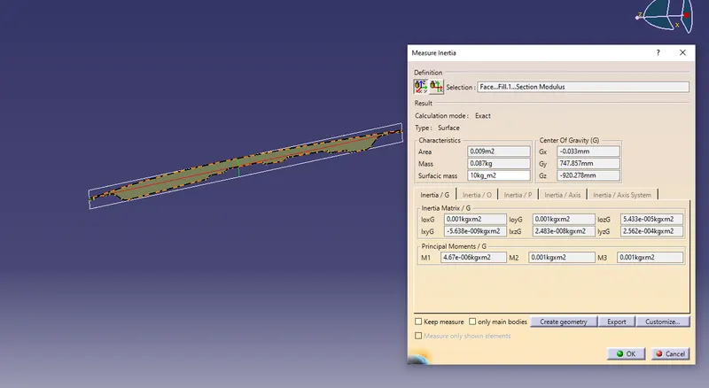
-
put all the value obtained in a given formula to calculate moment of inertia
i.e, S = I/y
where,
I = 4.67*10^-6 m^4 =4.67*10^4 mm^4
y = 486.99/2 = 243.495 mm
we get
S = 191.790 mm^3
CASE 2 :
Increase the Area of cross section of the hood by increasing the gap between the inner and the outer panel by 0.5 mm
- Measure the inertia by using Inertia command (I)
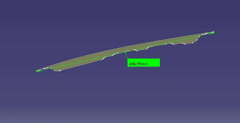
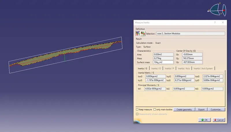
with the same lenght (y) put all the values in the formula to get section of modulus
S = I/y
where,
I = 4.403*10^-6 m^4 = 4.403*10^4 mm^4
y = 486.99 /2 = 243.495 mm
we get,
S = 180.825 mm^3
Comparision of CASE 1 and CASE 2
When we compare case 1 of section modulus to the case 2 of section modulus, the case 2 section of modulus is more than case1, it means the section of modulus is directly propotional to the area of cross section, and we can also say strength and load bearing capacity is more case 2 compared to case 1
Conclusion:
Thus the section of mudulus increases, more strength the material have and section of modulus is directly propotional to the area of cross section