Section Modulus calculation and optimization
AIM:
To calculate the Section Modulus for the Hood design for analyzing its strength and to optimizes hood design to improve the overall section modulus.
INTRODUCTION:
Section modulus is a geometric property of a structural cross-section that measures its ability to resist bending moments. It is a crucial parameter in structural engineering and is used to analyze the flexural strength of beams, columns, and other structural members.
The section modulus S of a cross-section is defined as the ratio of the moment of inertia I to the maximum distance from the neutral axis to the outermost fiber y. Mathematically, it can be expressed as:
S=I/y
S=Section Modulus.
I= Moment of Inertia.
y= Distance between the neutral axis and the extreme end of the object.
Moment of Inertia:
The moment of inertia of a cross-section, often denoted as I is a measure of a structural member's resistance to bending. It quantifies how the mass of an object is distributed relative to a given axis, influencing its ability to resist bending or torsional forces.
In the context of structural engineering, the moment of inertia is crucial for analyzing the behavior of beams, columns, and other structural elements subjected to bending moments. The greater the moment of inertia, the more resistant the member is to bending.
For different cross-sectional shapes, such as rectangular, circular, or I-beam, the formulas for calculating the moment of inertia differ. Generally, the moment of inertia is calculated as the sum of the products of each small elemental area of the cross-section and the square of its distance from the axis of interest.
For example, for a rectangular cross-section with width b and height h the moment of inertia about an axis perpendicular to the width and passing through the centroid (centroidal axis) is given by the formula:
I=1/12 XbXh³
b= Width
h=Height
These formulas provide a way to quantify the distribution of mass in a cross-section and its resistance to bending. The moment of inertia is a fundamental parameter in structural analysis and design, helping engineers ensure that structural members meet the required strength and stiffness criteria for a given application.
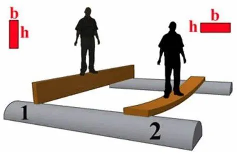
Certain shapes are better than others at resisting bending as demonstrated in the image. Clearly, the orientation of the shape also influences bending.
Let's work in CATIA how can we calculate the section modulus.
We have create the plane in the middle and the select outer most intersection line of outer panel and inner most intersection line of inner panel Create intersection by using Intersection tool image mention below.
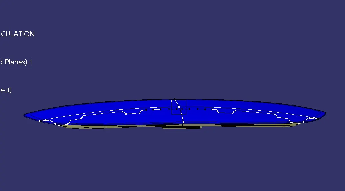
We clearly see in the image some of the gap was show so Fill the gaps by using Spline and make sure that there is no any gap or discontinuity.image mention below.

create a surface by using Fill command image mention below

And the by using measure inertia tools we can find the Moment of Inertia of any shape of 2D geometry.
CASE-1 ANALYSIS
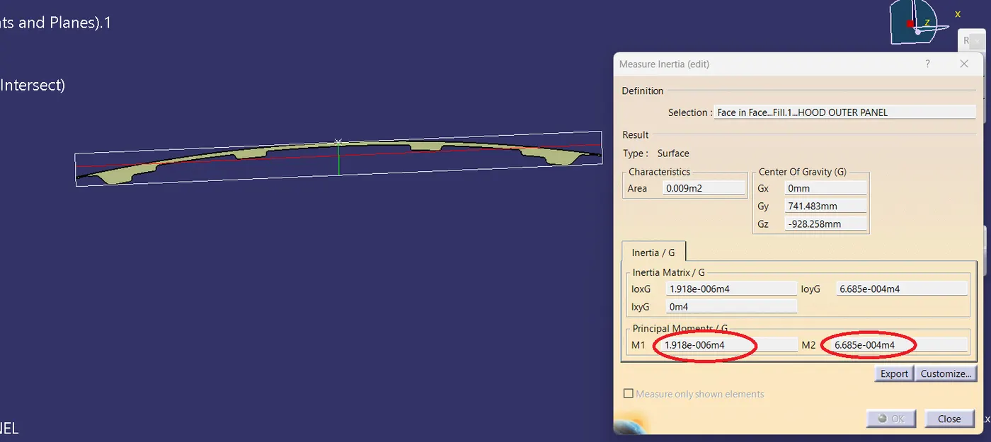
As per the image
M1 and M2 are the inertia values. as they are in meters (M) Convert them into mm4. For calculating the section modulus, we take the smaller value of M (which is M1 here).
Calculation:
M1= 1.918x10^-6 m^4
M2= 6.685x10^-4 m^4
A standard method of denoting moment of inertia is to write the value mm^4.
M1= 1.918x10^-6x10^12 mm^4 = 1.918x10^6 mm^4
M2= 6.685x10^-4x10^12 mm^4 = 6.685x10^8 mm^4
So the forumla is S=I/y
S1=I/y
M1= 1.918x10^6 mm^4
For y vaule we measure the Distance between the neutral axis and the extreme end of the object
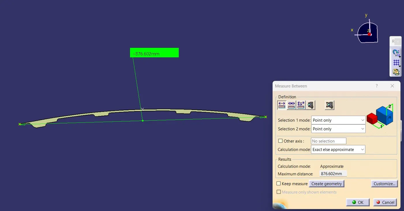
y= 876.602/2 = 438.301
S1 = 1.918x10^6/438.301 = 4,375 mm^3
S1 = 4,375 mm^3
CASE-2 ANALYSIS:
As we need to improve the strength of the new hood which we are designing we need to do some rework.
Here I went with increasing the gap b/w the outer panel & the inner panel by offsetting the inner panel outer boundary at a value of 0.5mm.image mention below.
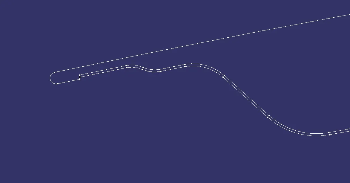
Thereby making it into a close-loop and filling it. And go for the measure inertia to get the M values. image mention below.

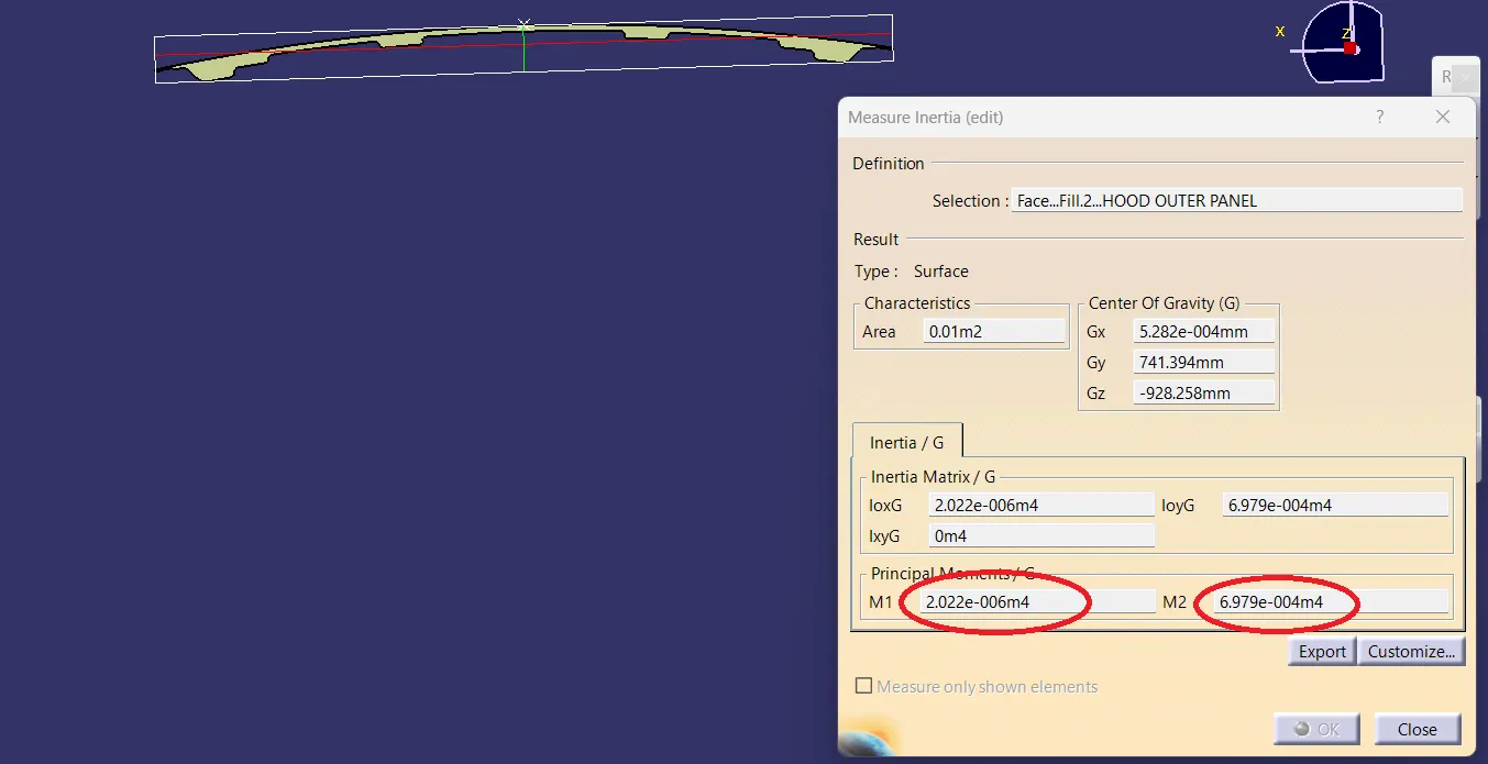
As per the image
Calculation:
M1= 2.022x10^-6 m^4
M2= 6.979x10^-4 m^4
M1= 2.022x10^-6x10^12 mm^4 = 2.022x10^6 mm^4
M2= 6.979x10^-4x10^12 mm^4 = 6.979x10^8 mm^4
M1= 2.022x10^6 mm^4
here the value of the Y remains same So, y= 876.602/2 = 438.301
S1=I/y
S1 = 2.022x10^6 /438.301 = 4,613 mm^3
S1 = 4,613 mm^3
Resulting by comparing case 1 & case 2
The section modulus value of case 2 is higher than the case 1
S1 = 4,375 mm^3 < S1 = 4,613 mm^3
CONCLUSION:
From the above analysis, we knew that larger section modulus will be stronger and capable of supporting greater loads. so from the above we can see that 2nd case has more section modulus than the 1st case so by increasing area we can get more stronger and capable of supporting greater loads.while design the hood we will consider the section modulus.