Section Modulus calculation and optimization
Section modulus
Section modulus is a geometric property for a given cross-section used in the design of beams or flexural members, it is also referred to as the Polar Modulus or the Torsional Sectional Modulus. Other geometric properties used in design include area for tension and shear, radius of gyration for compression, and moment of inertia and polar moment of inertia for stiffness. Any relationship between these properties is highly dependent on the shape in question. Equations for the section moduli of common shapes are given below. There are two types of section moduli, the elastic section modulus and the plastic section modulus.
Section modulus is directly dependent on the area moment of inertia and the distance from the neutral axis. Hence, to improve the geometry of the carry more bending load, the section modulus can be improved by increasing the area MOI of a given section
S=I/Y
Here,
S = Section modulus
I= Moment of Inertia (Unit mm 4)
Y= Distance from Neutral axis to the extreme end (unit mm)
The Unit of a “section modulus” is (mm3)
Equations for the section moduli of common shapes are given below.
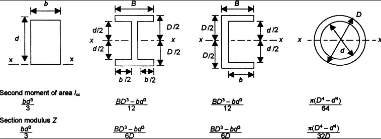
There are two types of section moduli,
- Elastic section modulus
- Plastic section modulus
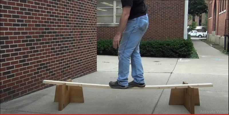
Changing the position can show the difference in bending which is because of the centroid distance from extreme fiber end.
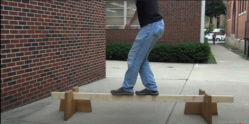
In Layman's terms, in this position there is more material from axis to the specific direction, to resist the load which makes less bend amd improves the strength.
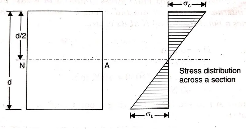
Neutral Axis:
- The centermost layer of any section of a component is called the Neutral axis.
- Neutral Axis doesn't get affected by any kind of load that is perpendicular to it which means there is no stress or strain on the neutral axis.
- The range of stress varies with respect to the distance from the neutral axis.
- The below figure shows the Neutral axis(dotted line) and in the Load situation the stress on either side of the neutral axis.
Elastic section modulus
For general design, the elastic section modulus is used, applying up to the yield point for most metals and other common materials.
The elastic section modulus is defined as S = I / y, where I is the second moment of area (or area moment of inertia, not to be confused with moment of inertia) and y is the distance from the neutral axis to any given fibre. It is often reported using y = c, where c is the distance from the neutral axis to the most extreme fibre, as seen in the table below. It is also often used to determine the yield moment (My) such that My = S × σy, where σy is the yield strength of the material.
We know the bending equation is
M/I = σ/y = E/R
FROM ABOVE EQ:-
M=I/Y*σ (WHERE I/Y=SECTION MODULOUS)
SO M IS DIRECTLY PROPESONAL TO SECTION MODULOUS
Where,
- M = Bending moment at the section, I= Moment of inertia of the section
- E = Modulus of elasticity of the beam
- σ = Bending stress or flexural stress at a distance y from the neutral axis
- R= Radius of Gyration
-
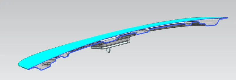
Section Modulus Analysis using UGNX:
-
-
Procedure for an increase in the area:
Case-1: Increasing the area by offsetting the outermost layer.
At Zero Offset:
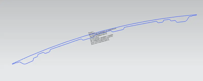
- Select the Part body on which we have to do analysis and create a cross-section of the part and make sure that the cross-section sketch is a closed profile.
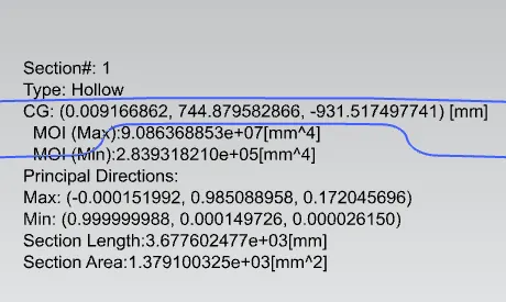
- Perform Section Inertia Analysis over the section that we have created and there we can find the result as shown below
- Create a CG point by using the point command and measure the distance between the point on the outermost layer and the CG point by using the measure command in analysis.
- Here the reason to take Y parallel to the x-axis is if we take the loading condition perpendicular to the x-axis then the Y value also increases as the Area increases but we have to keep one parameter constant for that we took the loading condition parallel to X-axis(this condition can be taken on a side impact).
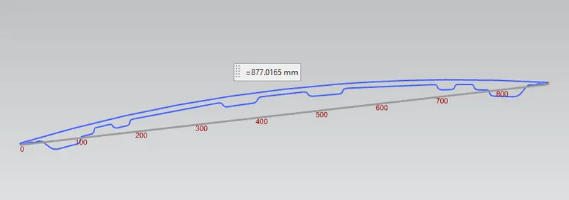
- The Distance we got here is 877/2=438.5mm
- According to the formula For section modulus
-
S = I/Y
-
Where,
S = Section Modulus
I = Moment of Inertia
y = distance between the neutral axis and the extreme end of the object
- MOI min/Y = (2.839318210x10^5)/438.5 = 647.507mm^3
- MOI max/Y = (9.086368853x10^7)/438.5 =207214.7971 mm^3
- Section Modulus at MOI min = 647.507mm^3
- Section Modulus at MOI max = 207214.7971 mm^3
At 0.5 mm Offset:
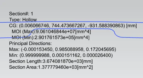
- MOI min/Y = (2.901761573x10^5)/438.5 = 661.7472002mm^3
- MOI max/Y = (9.061046844x10^7)/438.5 = 206637.3283 mm^3
- Section Modulus at MOI min = 661.7472002mm^3
- Section Modulus at MOI max = 206637.3283 mm^3
At 1 mm Offset:
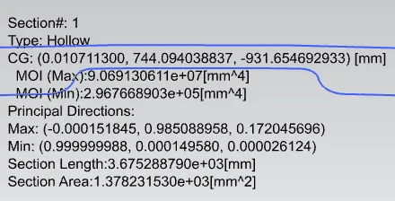
- MOI min/Y = (2.967668903x10^5)/438.5 = 676.7774009 mm^3
- MOI max/Y = (9.069130611x10^7)/438.5 = 206821.6787 mm^3
- Section Modulus at MOI min = 676.7774009 mm^3
- Section Modulus at MOI max = 206821.6787 mm^3
-
S.No Case Y(mm) Section modulus at min MOI (mm^3) 1 At Zero Offset 438.5 647.507 2 At 0.5 mm Offset 438.5 661.7472002 3 At 1 mm Offset 438.5 676.7774009
Result: From the above analysis we can say that the section modulus increases with an increase in offset value nothing but an increase in Cross-sectional area.