Section Modulus calculation and optimization
Section modulus is a geometric property used to measure the resistance of a cross-sectional shape, such as a beam or a column, to bending. It provides information about the shape's ability to withstand bending stresses and is crucial in structural engineering and design.
The section modulus is defined as the ratio of the moment of inertia of a shape about a given axis to the distance from that axis to the outermost point in the shape. Mathematically, it can be represented as:
Section Modulus (Z) = I / Y
where:
- Z is the section modulus
- I is the moment of inertia of the shape about the axis of interest
- Y is the distance from the axis to the outermost fiber.
The moment of inertia represents the distribution of an object's mass with respect to an axis of rotation. It determines how the object resists bending and depends on the shape and dimensions of the cross-section.
A larger section modulus indicates a greater resistance to bending. Therefore, beams or columns with larger section moduli are capable of supporting larger loads without experiencing excessive deflection or failure. Designers and engineers use section modulus to select appropriate structural members and optimize their designs for strength and stiffness.
It's important to note that section modulus is typically calculated differently for different cross-sectional shapes, such as rectangular, circular, or I-beam sections. Each shape has its own formula to determine the moment of inertia and the corresponding section modulus.
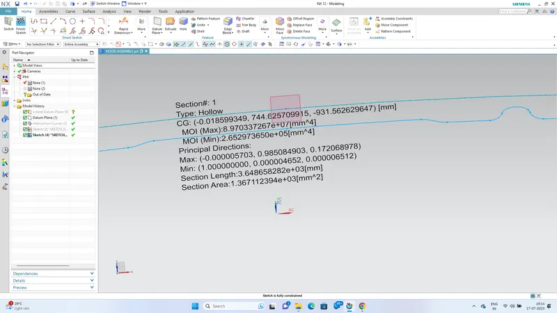
In this image, we can clearly see that the moment of inertia (I), which represents the area moment of inertia, is 2.65 * 10^5 mm^4. Additionally, the value of Y, which denotes the distance from the neutral axis to the outermost fiber, is calculated as half of 879.59, resulting in Y = 439.795. Thus, we can compute I/Y as (2.65 * 10^5 mm^4) / (439.795 mm) = 602.96 mm^3. Therefore, the section modulus (Z) is equal to 602.96 mm^3.
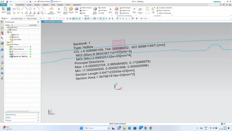
In this image, a new section has been introduced, which exhibits an improved section modulus compared to the previous one. The moment of inertia (I), representing the area moment of inertia, is determined as 2.69 * 10^5 mm^4. The distance from the neutral axis to the outermost fiber (Y) is calculated as half of 879.59, yielding Y = 439.795 mm. By dividing the moment of inertia (2.69 * 10^5 mm^4) by Y (439.795 mm), we obtain I/Y = 611.64 mm^3. Consequently, the section modulus (Z) is determined as 611.64 mm^3.
By analyzing the images, it is evident that the moment of inertia (I), representing the area moment of inertia, has increased to 2.69 * 10^5 mm^4. The moment of inertia describes how the mass is distributed around the neutral axis of a shape, influencing its resistance to bending. A higher moment of inertia indicates greater stiffness and resistance to bending.
Furthermore, the distance from the neutral axis to the outermost fiber (Y) is calculated as half of 879.59, resulting in Y = 439.795 mm. This distance represents the farthest point from the neutral axis and plays a crucial role in determining the section modulus.
To obtain the section modulus (Z), the moment of inertia (2.69 * 10^5 mm^4) is divided by Y (439.795 mm), yielding I/Y = 611.64 mm^3. The section modulus signifies the shape's ability to resist bending moments and is directly proportional to its strength and rigidity. A higher section modulus indicates an improved capacity to withstand bending stresses.
It is worth noting that the improved section modulus suggests that the new section design offers better structural performance, with increased resistance to bending compared to the previous design. This achievement can be attributed to various factors, such as modifications in the geometry, material selection, or reinforcement strategies.
In the process of developing the new section, the offset curve command with a value of 0.5 has been employed. The offset curve command is a geometric operation that generates a new curve or shape by offsetting an existing curve by a specified distance. In this case, an offset curve with a value of 0.5 has been applied, indicating that the new section has been created by shifting the original shape outward by 0.5 units.
By utilizing the offset curve command, engineers and designers can explore different cross-sectional configurations, optimize the section properties, and tailor the structural performance according to specific design requirements.
Overall, the introduction of the new section, achieved through the use of the offset curve command, has resulted in an improved Section Modulus, indicating enhanced resistance to bending and improved structural performance compared to the previous design.