Section Modulus calculation and optimization
Section Modulus:
Section modulus is the property of the cross-section that is used while the design of beams.
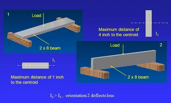
Section Modulus is simply defined has the ratio of the bending moment to the bending stresses OR It is also defined has the ratio of moment of inertia of the beam cross section about the neutral axis to the distance of the extreme fiber from the neutral axis
S= I/Y
Where s= Section modulus
I= Moment of inertia
y= Distance between the neutral axis and extreme end of the object
Section modulus is the geometric property for the given cross sectional area used in the design of flexural members other geometric properties used in the design include radius of gyration (K), moment of inertia(I) and the polar moment of inertia for stiffness. Any relationship between these particles remain highly dependent. There are two kinds of section modulus they are elastic section modulus and plastic section modulus.
The section modulus is classified into two types:-
1, Elastic section modulus:-
The elastic section modulus is applicable up to the yield point of material. It is used in most engineering applications.
2, Plastic section modulus:-
The plastic section modulus is generally used for material in which plastic behavior is observed.
Steps to calculate section modulus:-
Step 1:- Find the location of the centroid of the given cross-section.
Step 2:- Find the moment of inertia about a neutral axis (INAINA)
Step 3:- Find Ymax from the neutral axis.
Step 4:- Find section modulus using the formula provided above.
Section modulus for the hood assembly :
Section 01:
For determine the section modulus of the hood we need to create the datum plane at the center
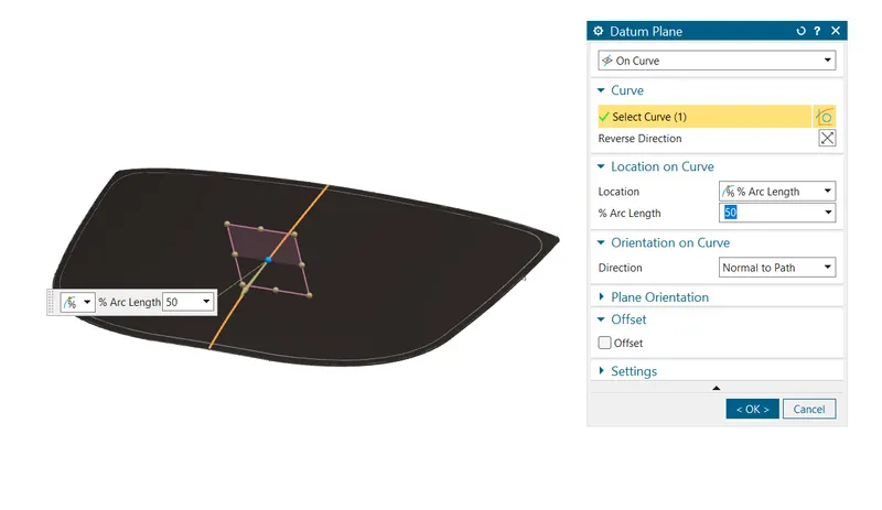
Now, create the intersection curve of the assembly with respect to the datum plane
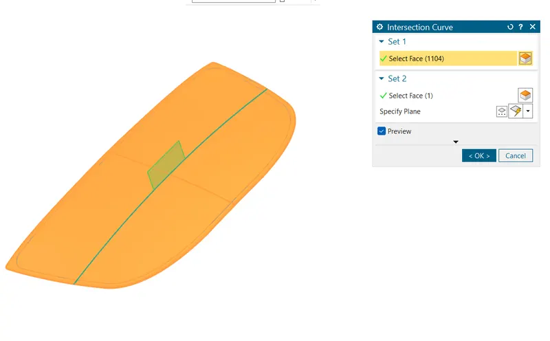
Now the intersection curve obtained is
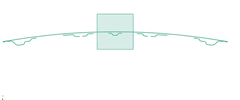
Now, use the spline to join the gaps in the intersection curve
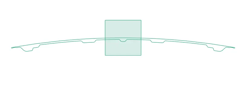
Once the sketch is fully constrained use the section inertia modulus feature to find the following
1.Maximum moment of inertia
2.Minimum moment of inertia
3.Centre of gravity
4.Coordinate locations
5.Section length
6.Area of the section
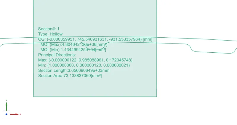
So we need to consider the minimum moment of inertia as if we increase the minimum moment of inertia value the more safety and strengthen the member
so the I value is 1.434499425*10^4 mm^4
value of the Yis
Y=885.7/2
so the value of the Y is 442.85mm
the section modulus Z is Z = I /Y
Z = (1.434499425*10^4) / 442.85 mm^4 / mm
so, Z 1 = 32.3924mm^3
Section 02:
The obtained section modulus value of the hood assembly can be modifiedc and improved and lot of methods are deployed to attain good strength to the member
The method I enclose over here is creating an extra emboss
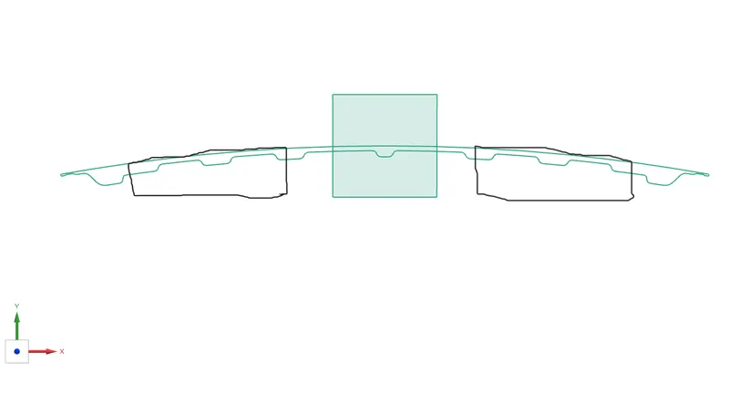
Now , find out the inertia modulus
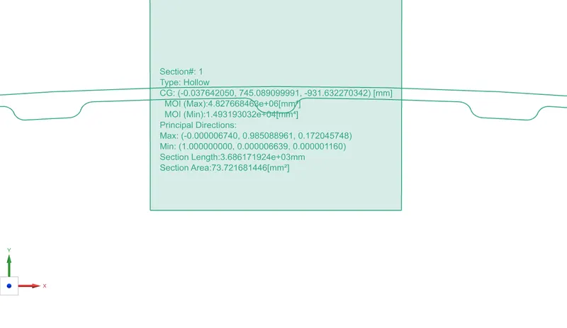
So the I value obtained is
I = 1.493193032*10^4 mm^4
and the Y value remains unaltered so , Y = 442.85 mm
So, the section modulus is
Z = (1.493193032*10^4) / 442.85 mm^4/ mm
so, Z 2 = 33.7178 mm^3
CONCLUSION:
In this study, we take the minimum of inertia moment to analyze the minimum limit of hood deformation. Thus the section modulus of the front hood was calculated and compared with the new design.
The section modulus value of section#2 is higher than section#1
Mass moment of inertia increases and which inturn reflects in the increase in the bending moment and leads to deeply strength to the member at high impact loads so section 02 is highly recommended.