Section Modulus calculation and optimization
Secttion Modulus:-
The section modulus is an important geometric property used in the design of beams or flexural members. It is also known as the Polar Modulus or the Torsional Sectional Modulus. In addition to the section modulus, other geometric properties like area, radius of gyration, moment of inertia, and polar moment of inertia are utilized in design calculations, each serving a specific purpose.
The relationship between these properties varies significantly depending on the shape being analyzed. Different shapes have different equations for calculating their section moduli. It's essential to consider the specific shape of the cross-section when determining its properties.
There are two types of section moduli commonly used: the elastic section modulus and the plastic section modulus. These two measures describe the resistance of the cross-section to bending under different conditions. The elastic section modulus relates to the material's elastic behavior, while the plastic section modulus relates to its plastic behavior.
Overall, the section modulus is a fundamental parameter used to assess the strength and stiffness of a cross-section, aiding in the design of structures subjected to bending loads.
S=I/Y
Here,
S = Section modulus
I= Moment of Inertia (Unit mm 4)
Y= Distance from Neutral axis to the extreme end (unit mm)
The Unit of a “section modulus” is (mm3)
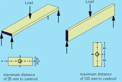
Certainly! Here are the section modulus formulas for some common shapes:
| Cross-sectional shape | Figure | Equation | Comment |
|---|---|---|---|
| Rectangle |  |
Solid arrow represents neutral axis | |
| doubly symmetric I-section (major axis) | 
|
NA indicates neutral axis | |
| doubly symmetric I-section (minor axis) |  |
NA indicates neutral axis | |
| Circle |  |
Solid arrow represents neutral axis | |
| Circular hollow section |  |
Solid arrow represents neutral axis | |
| Rectangular hollow section |  |
NA indicates neutral axis | |
| Diamond |  |
NA indicates neutral axis | |
| C-channel | |
NA indicates neutral axis |
 ,
,
For Design Study:-
For First Sketch:-
We can get the section modulus for a certain part by creating intersection curve on a datum plane, For getting a proper section inertia analysis we should have a closed sketch and then by using section inertia analysis we should select the curve and have to define its hollow thickness whioch is 0.75mm As we have assigned the thickness.
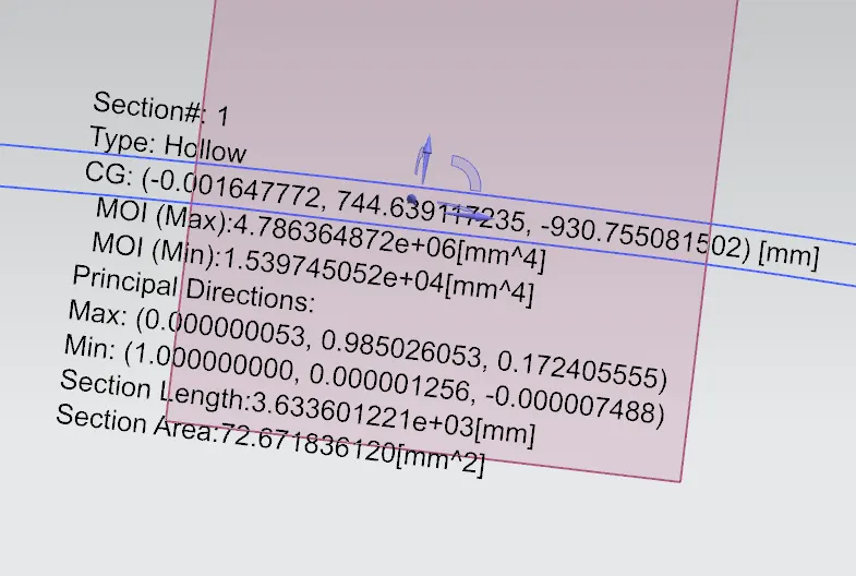
Here i have got a Moment of inertia as under:-
Moment of inertia(max) = 4.786×10^6×mm^4
Moment of inertia(min) = 1.5397×10^4×mm^4
Y=879.2520/2=439.625mm
S=I/Y
S=1.5397×10^4/439.625= 35.02^4
Hood Design update for sketch 2:
By increasing the depth of the inner panel by 0.5 mm
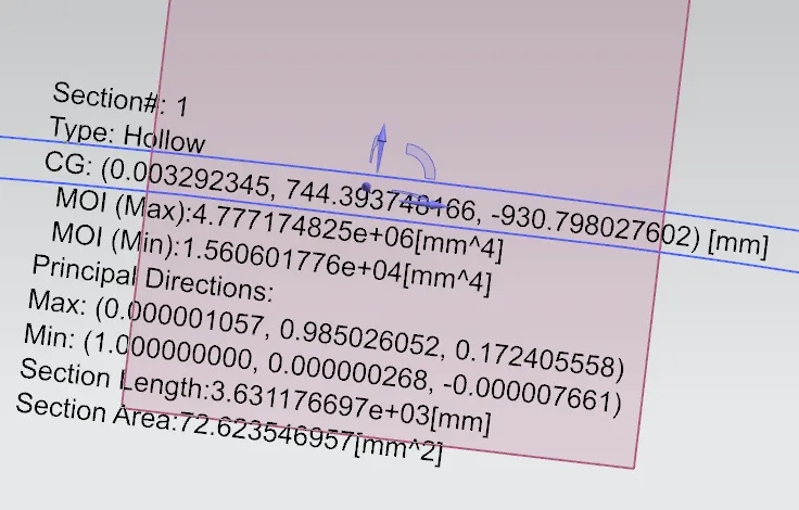
Here i have got a Moment of inertia as under:-
Moment of inertia(max) = 4.7771×10^6×mm^4
Moment of inertia(min) = 1.5606×10^4×mm^4
Y=879.2520/2=439.625mm
S=I/Y
S=1.5606×10^4/439.625= 35.49mm^4
So, here the difference can be seen in the moment of inertia and the change in the section modulus can be seen by the change in the design(depth).
Here, I got a very less variation between both surfaces butb accordingly we can get more differences by changing the embosses for future references.