Section Modulus calculation and optimization
Any structure which is constructed for carrying loads will be measured for various factors to predict their stiffness, strength and rigidity. These includes Section Modulus, Moment of Inertia and Modulus of Elasticity.
Section Modulus:
Section Modulus is an study of any cross-sectional strength about an neutral axis. It is the ratio of the Moment of Inertia of the beam cross-section about an Neutral axis to the extreme fibre from the neutral axis.
Section Modulus of an cross-sectional shape has an vital role in designing beams, since they are stronger and capable of greater loads.
The elastic modulus is donoted as Z. To calculate Z, the distance to the extreme fibres from the centroid must be found as that where the maximum stress could cause failure.
MOMENT OF INERTIA:
A structure is subjected to bending stresses at several locations.The bending stiffness of a structural member’s cross-sectional shape is measured using the moment of inertia.
Moment of inertia is a direct measure of the resistance offered by the body to angular acceleration about a gien axis.The mass is divided into several elemental masses and the sum of the product of each elemental mass and the square of their distance from the given axis gives the moment of inertia of the structure. If the moment of inertia of material is large then the bending stiffness of the structure is also high.
MODULUS OF ELASTICITY:
The ratio of stress to strain or the stiffness of the material of a structural member (resistance to deformation).It is essentialy a generic term to measure the overall stiffness of the material. So as the modulus of elasticity of the material increases so does the stiffness of the material.
Case 1 : Section modulus of the initial hood structure
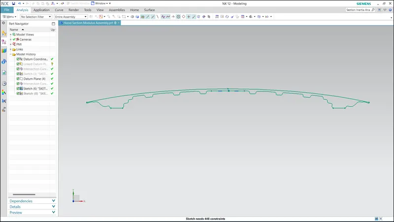
In the hood, a datum plane was created in the middle of it. I had deactivated all the other parts like hinge assembly and latch and striker because eitherway i want intersection curve of Inner and Outer Plane of the Hood respective to the Datum Plane created in the middle of It.
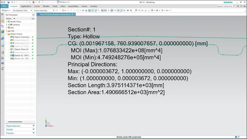
Now, Using Intersection Curve, I projected the cross-sectional curves respective to the datum plane. After that the outer curve of Hood outer and Inner plane were retained using 2D Project Curve. and it was brought to closed curve by using profile tool. By Using Section Inertial Analysis Tool, Minimum and Maximum moment of Inertia , Section Length and Section Area were finded.
Case 2 : Modified Hood
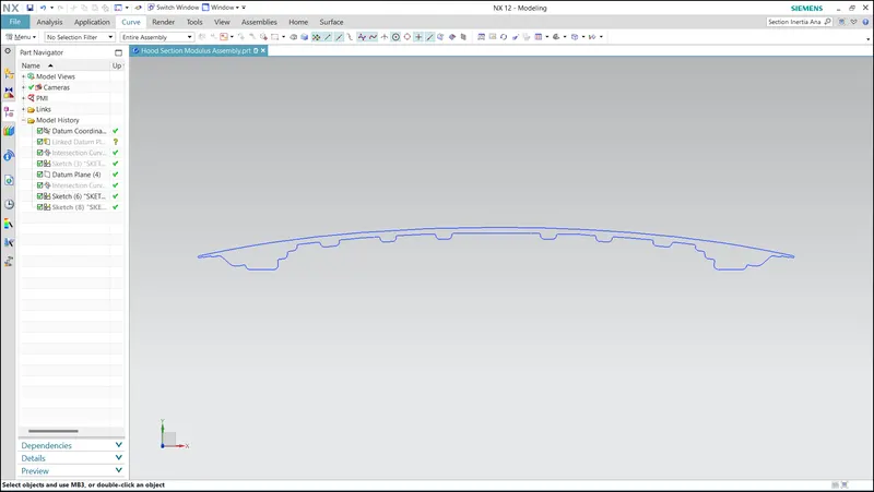
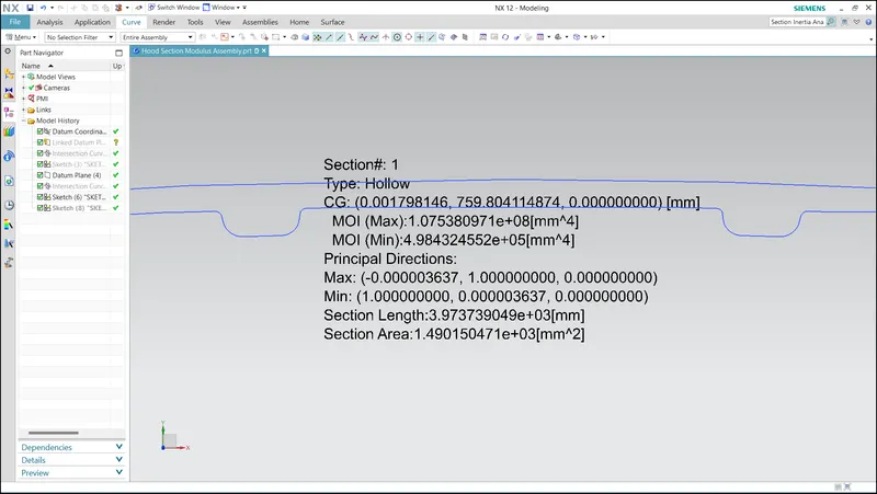
The Inner Panel Hood Curve was offseted to 2mm to increase the moment of Inertia. It can also be increased by adding Embosses.
Calculations:
Total Distance:
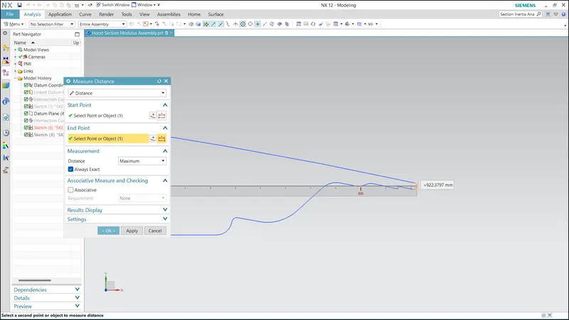
Section modulus (Z)=Minimum moment of inertia(I) /Distance of the extreme fibers from the neutral axis(y)
Z=I/y
Z1-Section modulus of the initial hood design
Z2-Section modulus of the final hood design with additional embossess to increase the section area , section modulus thereby increasing the strength of the material
Initial hood design - Section modulus
Z1=(4.7492e^5 mm^4)/(461.1895 mm)
Z1=102.977 mm^3
Modified hood design -Section modulus
Z2=(4.9843e^5 mm^4)/(461.1895 mm)
Z2=108.074 mm^3
| S.No | Hood Model | Section Area | Minimum Moment of Inertia | Distance from the Neutral Axis | Section Modulus |
| 1 | Hood Model before Modifications | 1.490666512e+03 mm^2 | 4.7492e^5 mm^4 | 461.1895 mm | 102.977 mm^3 |
| 2 | Hood Model after Modifications | 1.490150471e+03 mm^2 | 4.9843e^5 mm^4 | 461.1895 mm | 108.074 mm^3 |
Conclusion:
From this study, the modified Hood Design has increased Moment of Inertia and Section Modulus than the original Hood Design.