Section Modulus calculation and optimization
Project Objective: To calculate the Section Modulus of the Hood Inner panel and Outer panel Design and Optimization of the Hood Design.
Section Modulus:
Section modulus is a geometric property of a structural cross-section that is used to calculate the bending stress in a beam or other structural member. It is defined as the ratio of the moment of inertia of the cross-section to the distance from the neutral axis to the outermost point of the section.
In mathematical terms, the section modulus (S) is calculated as:
S = I / y
Where I is the moment of inertia of the cross-section and y is the distance from the neutral axis to the outermost point of the section.
Types of section modulus are:
- Elastic Section Modulus
- Plastic Section Modulus
- Torsional Section Modulus
- Warping Section Modulus
Significance of Section Modulus:
Determining maximum bending stress: Section modulus is used to calculate the maximum bending stress that a beam or other structural member can withstand before it fails due to bending stresses. This is important in designing structures to ensure they can withstand the expected loads without failure.
Comparing cross-sections: Section modulus allows for easy comparison of the resistance of different cross-sections to bending stresses. It helps designers to choose the most efficient cross-section that minimizes material usage while meeting the design requirements.
Material selection: Section modulus is a critical factor in material selection for structural members subjected to bending stresses. By comparing the section module of different materials, designers can select the most suitable material for the application.
Analysis of existing structures: Section modulus can be used to assess the strength of existing structures and determine if they can safely carry the expected loads. This is important in evaluating the safety of structures and deciding on any necessary repairs or upgrades.
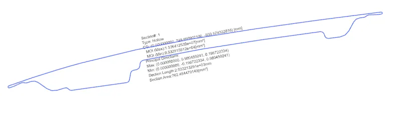
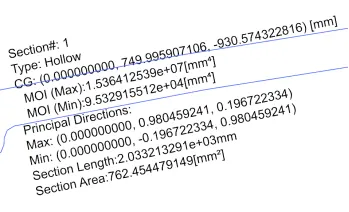
Section Modulus of Old Model
Along X - Axis
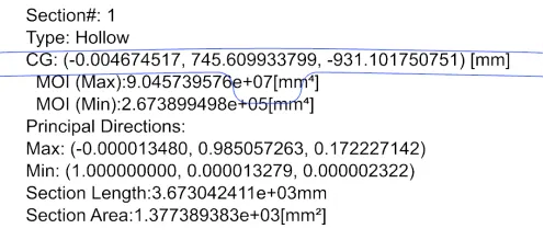
Along Y - Axis

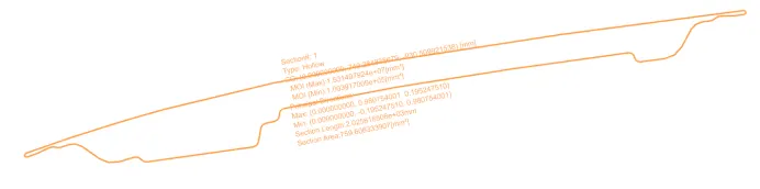
Section Modulus of Improvised Model:
Along X - Axis
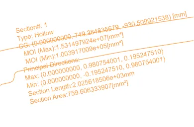
Along Y - Axis

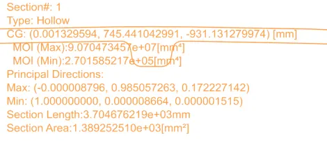
In order to increase the moment on Inertia of the Outer and Inner Panel of the Hood, I have reduced the height of the 1st emboss from 10mm to 7mm and there is no change on the second emboss.
Moment of Inertia (Old Model vs Improvised Model)
|
MOI (Min) |
Along X Axis |
Along Y Axis |
|
Old Model |
9.5329 X 104 mm4 |
2.6738 X 105 mm4 |
|
Improvised Model |
1.0039 X 105 mm4 |
2.70158 X 105 mm4 |
Conclusion: In the above mentioned table, we can see that the MOI has been increased along with X and Y axis after increasing the cross section area of the model.
Hence, MOI is directly proportional to the Increase in the cross section area of the model.