Section Modulus calculation and optimization
Aim
To calculate the section modulus of the previously designed hood for analyzing its strength and also optimizing the design to see the difference in the bending strength of the hood. Higher the section modulus of a structure, the more the resistive it becomes to bending.

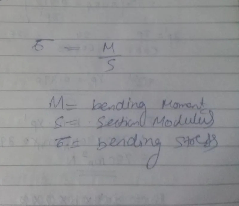
 is the Bending Moment
 is the Moment of Inertia of the section
 is Young's Modulus
 is the Radius of curvature
 is the stress at a distance
  from the Neutral Axis
Section modulus
Section modulus is a geometric property for a given cross-section used in the design of beams or flexural members, it is also referred to as the Polar Modulus or the Torsional Sectional Modulus. Other geometric properties used in design include area for tension and shear, radius of gyration for compression, and moment of inertia and polar moment of inertia for stiffness. Any relationship between these properties is highly dependent on the shape in question. Equations for the section moduli of common shapes are given below. There are two types of section moduli, the elastic section modulus and the plastic section modulus.
S=I/Y
Here,
S = Section modulus(unit in mm3)
I= Moment of Inertia (Unit mm 4)
Y= Distance from Neutral axis to the extreme end (unit mm)
Elastic section modulus
For general design, the elastic section modulus is used, applying up to the yield point for most metals and other common materials.
The elastic section modulus is defined as S = I / y, where I is the second moment of area (or area moment of inertia, not to be confused with moment of inertia) and y is the distance from the neutral axis to any given fibre. It is often reported using y = c, where c is the distance from the neutral axis to the most extreme fibre, as seen in the table below. It is also often used to determine the yield moment (My) such that My = S × σy, where σy is the yield strength of the material.
| Cross-sectional shape | Figure | Equation | Comment |
|---|---|---|---|
| Rectangle |  |
Solid arrow represents neutral axis | |
| doubly symmetric I-section (major axis) | 
|
NA indicates neutral axis | |
| doubly symmetric I-section (minor axis) |  |
NA indicates neutral axis | |
| Circle |  |
Solid arrow represents neutral axis | |
| Circular hollow section |  |
Solid arrow represents neutral axis | |
| Rectangular hollow section |  |
NA indicates neutral axis | |
| Diamond |  |
NA indicates neutral axis | |
| C-channel | |
NA indicates neutral axis |
 ,
,
Neutral axis
The neutral axis is an axis in the cross section of a beam (a member resisting bending) or shaft along which there are no longitudinal stresses or strains. Building trades workers should have a basic understanding of the concept and follow industry rules and guidelines, to avoid dangerously compromising the structural safety of a building.
Plastic section modulus
The plastic section modulus is used for materials where elastic yielding is acceptable and plastic behavior is assumed to be an acceptable limit. Designs generally strive to ultimately remain below the plastic limit to avoid permanent deformations, often comparing the plastic capacity against amplified forces or stresses.
The plastic section modulus depends on the location of the plastic neutral axis (PNA). The PNA is defined as the axis that splits the cross section such that the compression force from the area in compression equals the tension force from the area in tension. So, for sections with constant yielding stress, the area above and below the PNA will be equal, but for composite sections, this is not necessarily the case.
The plastic section modulus is the sum of the areas of the cross section on each side of the PNA (which may or may not be equal) multiplied by the distance from the local centroids of the two areas to the PNA:

the Plastic Section Modulus can also be called the 'First moment of area'
The plastic section modulus is used to calculate the plastic moment, Mp, or full capacity of a cross-section. The two terms are related by the yield strength of the material in question, Fy, by Mp=Fy*Z. Plastic section modulus and elastic section modulus are related by a shape factor which can be denoted by 'k', used for an indication of capacity beyond elastic limit of material. This could be shown mathematically with the formula :-

First Design Study
The Intersection of the design was taken and then section Inertia Analysis was done-
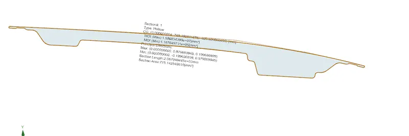
Moment of inertia(max) = 1.58634×10^7×mm^4
Moment of inertia(min) = 1.187649711×10^5×mm^4
Y=488.9/2=244.45 mm
S=I/Y
Smax=1.58634×10^7/244.87=6491.44 mm^3
smin=1.187649711×10^5/244.87 =485.85 mm^3
Hood Design Optimization
By increasing the depth of the inner panel by 10 mm
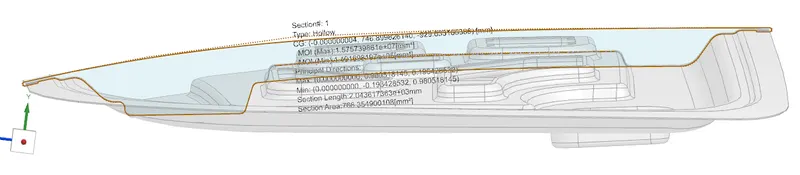
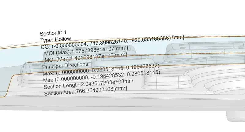
Moment of inertia(max) = 1.575739861×10^7×mm^4
Moment of inertia(min) = 1.401698197×10^5×mm^4
Y=488.9/2=244.45 mm
S=I/Y
Smax=1.57573961×10^7/244.87=6444.496 mm^3
smin=1.401698197×10^5/244.87 =573.31 mm^3
Hood Design Optimization
By increasing the applying emboss to the section
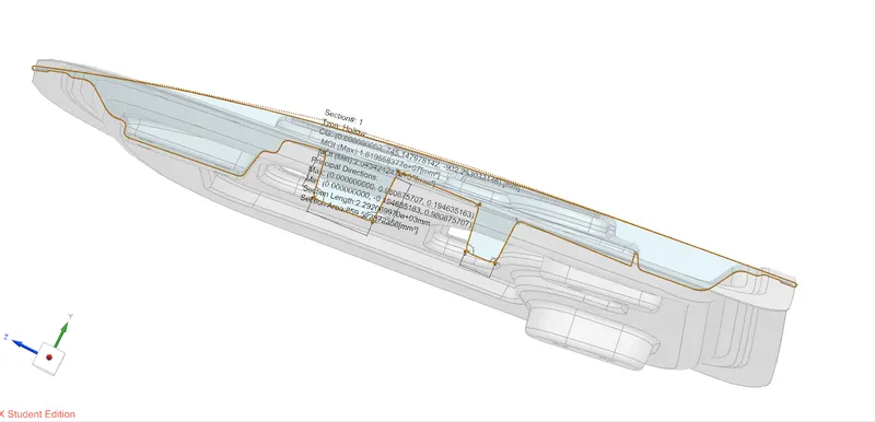
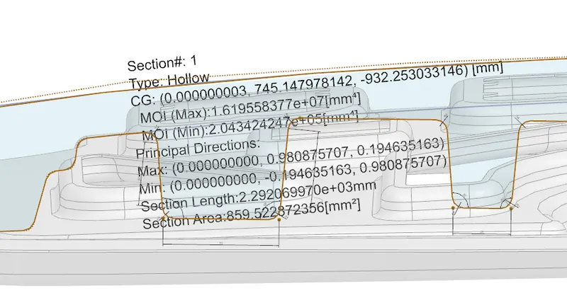
Moment of inertia(max) = 1.61955877×10^7×mm^4
Moment of inertia(min) = 2.043424×10^5×mm^4
Y=488.9/2=244.45 mm
S=I/Y
Smax=1.57573961×10^7/244.87=6625.317120 mm^3
smin=2.043424×10^5/244.87 =835.925 mm^3
Conclusion