Radar Mast & Final Assembly of Yacht
Design, assembly and rendering of american predator yacht
objective
The objective of the project to create and design every parts of model then assembling in solidwork assembly and to create a photo realistic of yatch.
Introduction
In this project the american predator yatch is taken as conceptional model, to understand the 3d modelling methodology of solid modelling and surface modelling.each and every part of the yacht was designed and modelled using solidworks.Then the modelled parts were assembled by adding proper mates and constraints to create the photo-realistic rendered image of the yacth.
The solidworks is mechanical design automation application that lets designers quickly sketch out ideas,experiment with features and dimensions,and produce models and detailed drawings.
Design approch
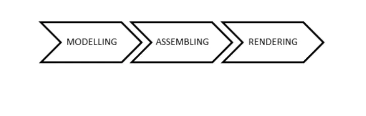
Design methodology
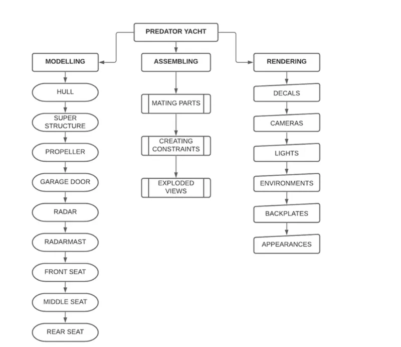
Type of commands used in solidworks to design yacht
a. part files
1. sketch
2. feature manager
3. surfacing
4. render tools
b. assembly files
1. assembly
2. render tools
sketch commands
1. sketch- sketch is a 2d drawing is created to change into feature 3d modelled or also using different features like surface, sheetmetal etc.
2. 3d sketch- 3d sketch is most useful tool when we want to draw in 3 dimensions x,y and z then we used this tool in 3d modelling of sweep command,surfacing modelling, weldments etc.
3. line- line is basic command of sketch to draw a sketch with horizontal, vertical and inclined lines with showing of construction, centre and defined lines for sketch.
4. circle- a circle is another important sketching tool in sketch had two type of sketch given to draw with "perimeter' and "centre circle".
5. Rectangle- sketch rectangle and square with centre point at selected angle.
6. spline- a two or three dimensional curve defined by a set of control points. points with spline. points with spilne is should be added or deleted.
7.sketch fillet- a tangent arc between two sketch entities to be created.
8. offset entities- copy a sketch entities with specific distance from original sketch entities. must have sketch entities already drawn and selected to used this tool.
9. sketch picture- insert a image file into the background of sketch. this allow the user to create 2d sketch bassed off the image.
10. convert entities- Whenever we need to make a sketch entity that matches other geometry of our model we can use the Convert Entities tool.
feature commands
1. boss extrude/ cut extrude- The Boss-Extrude/Base feature will project a 3D model with the selected sketch or face. Using the 2D sketch or plane to create a 3D model. same cut extrude is work similar like boss but difference is its removing material of 3d model by 2d sketch we draw on plane or face of model.
2. split- lines are used to split face and surface of 3d model into two or more many as our sketch we create and surface and face of model we choose to spilt. They must be haved oriented so that they will pass through faces when projected through normal on model.
3. dome- It creates a dome that is tangent to the adjacent cylindrical or conical face.
4. sweep- a sweep is a tool that creates a solid, a cut or a surface feature by moving a profile along a path. To create a solid, use the Swept Boss tool to move a profile along a path. The profile can contain one or more closed contours.
5. Revolve- the Revolve feature creates geometry from a sketch. However, the Revolve requires one more ingredient, the Axis of Rotation. Once you have a sketch, the next element is the center line, axis or internal line, of the sketch.
6. projected curves- You can create multiple closed or open-contour projected curves from a single sketch. You can also use 3D sketches as input for the Projected Curve tool. The Projected Curve tool does not support projections of intersecting curves. You can project curves from 2D and 3D sketches, onto faces and planes.
7.composite curves-composite curves are used to merge two projected curves by on segment.
surface commands
1. extrude surface-Extruding Surfaces from a 2D or 3D Face.You can create extruded surfaces from models that include 2D or 3D faces and knit the extruded surfaces to surrounding features.
2. swept extrude-To create a swept surface: Create planes for sketching the sweep profile, sweep path, and if necessary, the guide curves. Sketch the sweep profile and path on the planes that you created. You can also sketch the sweep path on a model face or use a model edge for the path.
3. loft surface-The loft feature is an important tool for (surface) modeling in SolidWorks. The loft feature creates a shape by making transitions between multiple profiles and guide curves. This tool is very valuable for modeling complex surfaces. You can do some really cool stuff when you use this feature properly.
4. boundary surface-The boundary surface feature lets you create surfaces that can be tangent or curvature continuous in both directions (all sides of the surface). In most cases, this delivers a higher quality result than the loft tool.
5.filled surface-The Filled Surface feature constructs a surface patch with any number of sides, within a boundary defined by existing model edges, sketches, or curves, including composite curves. You can use this feature to construct a surface to fill a gap in a model.
6.offset surface-we create offset surface from created surface with given distance.
7. Ruled surface- The Ruled Surface command creates surfaces that extend out in a specified direction from selected edges. Examples of how you can use ruled surfaces: Add tangent extensions to complex surfaces. Create drafted sidewalls. Replace non-drafted surfaces on imported models with drafted surfaces.
8.fillet- Fillet/Round creates a rounded internal or external face on the part. You can fillet all edges of a face, selected sets of faces, selected edges, or edge loops.
9.extend surface- Extends one or more edges or faces on a surface, based on end conditions and extension type.
10. Trim Surface – It trims the surfaces where a surface intersect with another surface, a plane or a sketch.
11. Reference plane – We can create planes in part or assembly documents. We can use planes to sketch, to create a section view of a model, for a neutral plane in a draft feature, and so on.
12. Projected curve – A projected curve is typically used either in sweeps and lofts as path or guide curve. There are two types of projected curves:
- Sketch on Sketch: Use two sketches to make a single curve.
- Sketch on surface: Use a sketch to project on a surface.
13. Split line – The Split Line tool projects an entity (sketch, solid, surface, face, plane, or surface spline) to surfaces, or curved or planar faces. It divides a selected face into multiple separate faces. We can split curves on multiple bodies with one command.
14. Split entities – We can split a sketch entity to create two sketch entities. Conversely, we can delete a split point to combine two sketch entities into a single sketch entity.
PART MODELLING
BLUEPRINT
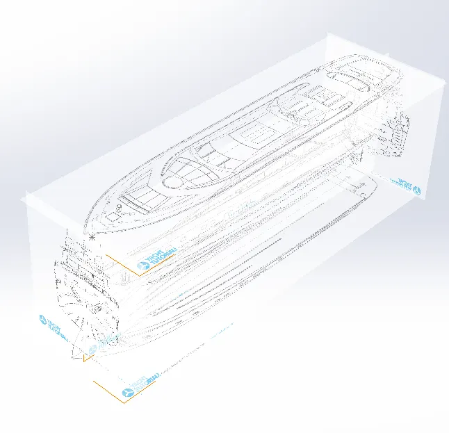
The above shown Blueprint was used to model the Yacht in a fully defined constraints. For setting up the Blueprint the Sketch pictures options were used and placed the different blueprints at the required planes.
1. HULL
The hull is the body of a vessel, without taking into account the rigging (ropes, chains, and tackle used to support and work masts, sails, etc.). The structure of the hull is composed of several different parts.
Parts of the Hull
A vessel’s hull is its framework or shell and can be constructed of diverse materials like iron, steel, rubber, wood, aluminum, glass fiber, concrete, polyester and many others.
If we were to stand facing the front of the vessel, the bow would be the front of the ship and the stern the rear, port would be the left side and starboard the right side of the vessel. Now that we have our bearings let’s list and describe the parts that compose the hull of a vessel, and explain their functions.
Bow and Quarters
The bow is the area of the hull that curves into the front, the sides to the front of the vessel are known as port bow and starboard bow.
Same can be said of the quarters, the curved part of the hull located between the beam and the stern of the ship, there is a port quarter and a starboard quarter.
Tack is a nautical term for the side of a sailing craft from which the wind is coming while under way, the starboard or port tack. Also tacking is a sailing maneuver by which a sailing vessel turns its bow toward and through the wind so that the direction from which the wind blows changes from one side of the boat to the other, allowing progress in the desired direction.
The Keel and the bottom of the hull
The bottom of the hull is permanently submerged in the water and bears the maximum load weight. From the keel to the waterline, it is usually painted in red with an antifouling biocide to prevent marine life from attaching.
The volume is contained by the hull and the waterline of the vessel. It corresponds to the submerged volume of the vessel.
Topsides
Topsides refers to the part of the hull between the waterline and the deck and remains above sea level. From the waterline to the main deck. There’s where the superstructure is built
It also acts as a buoyancy reserve, which is the volume of a ship above the water plane that can be made watertight for buoyancy purposes.
Waterline
Separating the hull into two parts, topsides and bottom. It is also the name of a special marking, also known as an international load line, or Plimsoll line, indicating the draft of the ship. It is also called watermark, a line indicating the former level or passage of water.
The waterline may change depending on different factors such as the vessel’s load weight, stowage or the condition of the sea.
Bilge
Located under the engine room, it’s the part of the hull that would rest on the ground if the vessel were unsupported by water. Bilge pumps are installed to remove the collected dirty water after it’s filtered.
Oily water and other liquid substances drain into the bilge because of rough seas, rain, leaks in the hull or stuffing box, or other interior spillage from the engine room.
The resulting waste after filtering the waters is called bilge slop and must be stored safely and removed at port for its proper treatment.
Deck
The deck is the permanent covering over the hull or over a compartment. Vessels often have more than one, horizontally dividing the area to create floors or decks. They are made out of metal or wood laid over the beams and they strengthen the hull and serve as the primary working surface.
Decks have different purposes and specific names depending on the structure, form, function or the type of vessel. Some accommodate the passenger cabins, the engine control room, etc.
Winches, the binnacle, crew seating, or the helm itself are located on different parts of the functional and habitable area of the deck.
Keel
The keel is the bottom-most structural member around which the hull of a ship is built. The keel runs along the centerline of the ship, from the bow to the stern. A central beam to which the ribs are attached on each side.
At the prow the keel meets the stem, and the sternpost at the rear. The keel is where all parts of the vessel that make its frame are attached to.
Hull
The hull is the watertight body of a vessel, it envelopes its structure and creates the frame. It keeps the vessel afloat and stabilizes it
Hull Shapes
There are many possible shapes for a ship’s hull depending on the purpose for which it’s being built.
The most common hull shapes can be grouped in four categories: flat-bottom (more stability and favors planing), rounded (fishing boats, tugs, trawlers), v-shaped (most popular in recreational vessels) and multihull, like catamarans or trimarans.
In conclusion, the most important parts of the hull of a vessel have been described. Would you like to know more? Get in touch with Suisca Group, and we will gladly offer you all maritime sector related services.
COMMANDS USED TO MODEL
In Sketch
- Line
- Spline
- Circle
- Rectangle
- Arc
- Slot
- 3-D Sketch
- Sketch picture
In Surfaces
- Extruded Surface
- Revolved Surface
- Lofted Surface
- Surface Trim
- Surface Fill
- Surface Knit
- Delete Face
In Features
- Project Curve
- Chamfer
- Fillets
- Reference Plane
- Split
- Split Line
- Extruded BossBase
- Extruded Cut
- Mirror
MODELLING PROCEDURE
- The first step for modeling the Yacht was creating a blueprint of it.
- Then the blue print was placed at the required planes, by using it first the hull was designed.
- To get the shape of the hull the projected curve was produced by drawing the required sketch using splines with the help of blueprint.
- Then the curves were lofted to create a lofted surface and the remaining unwanted surface was trimmed using surface trim.
- Then the back portion of the hull were the propeller needs to be placed was extruded using Extruded Surface and all the surface created must be Knitted together to remove the gaps between the surfaces.
- Then the offset option was used and another surface was created and both surface was filled using surface fill to create the outer shell of the hull which will be converted into a solid body at last.
- Shell feature was used to create the front portion of the hull where the deck surface meets.
- Then the deck surface was created using Extruded Boss/Base and Extruded Cut.
- Then the required chamfers and fillets were created wherever necessary.
- All the windows and Portholes were created using Extruded Cut and Fillets were add around the edges.
- For creating the smooth edges around the berth window the reference plane were created and a circle for required dimensions were make pierced and then swept around the edge of the windows.
- The Rails at the bottom of the yacht were created using Extruded Boss/Base and the chamfers were applied both the sides.
- The Cable Rollers were created using Extruded Boss/Base and Swept Boss/Base and the head part of it was created using Revolved Boss/Base and Extruded Cut was used to cut through the extrude and a Dome was created over it.
- Helix/Spiral sketch was created to sweep the rope around the Cable Rollers.
- By using Slot option the Rope hangers were extruded and the dome was applied and then the Linear Pattern was used to create one more.
- The window bars were created using Extruded Boss/Base.
- The staircase was created by using extruded boss/base and the hand support bar was created using Swept Boss/Base.
- The Railings around the Hull was generated with the help of blueprint and the projected curve was produced and the railing reference was swept using Swept Boss/Base.
- The Axles for the propeller and the surfer were created using Revolved Boss/Base option and using the 3d sketch.
- The Anchors were created by sketching the first half and extruded using Extruded Boss/Base and the other half was mirrored.
- Finally the Garage Portion was created by using Extruded Cut and the portion was saved for later use by using Split option.
- By using the Split line option the Painting portion for our hull was split separately.
- Then the other half of the Hull and the Axle of the surfer and propeller was mirrored to form the complete hull using Mirror tool.
- Now the part was saved by adding proper appearances and fillets.
SUPER STRUCTURE
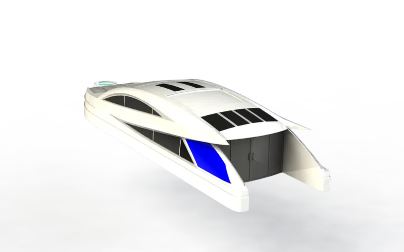
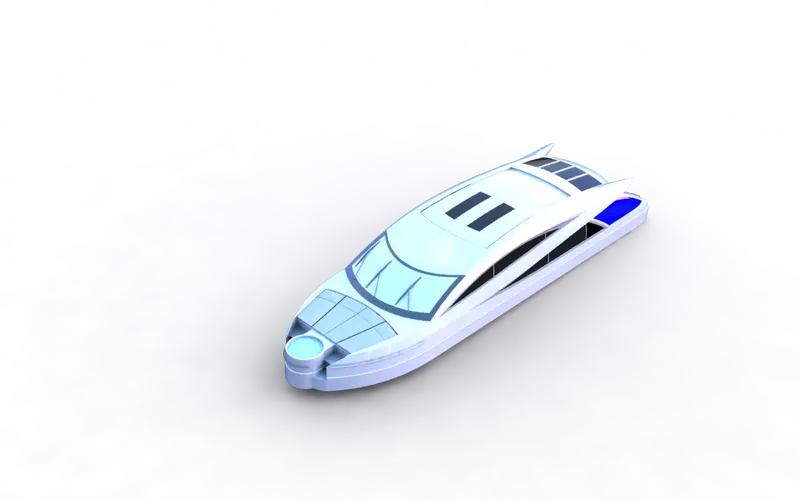
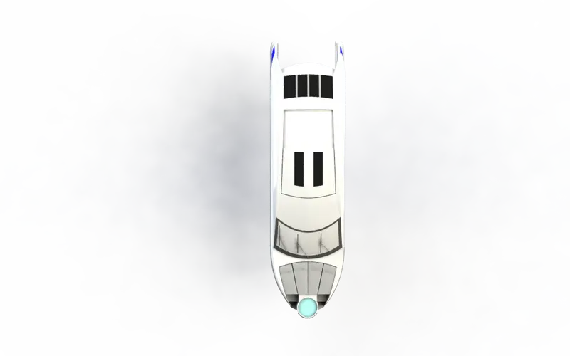
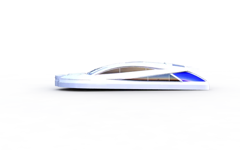
A superstructure is an upward extension of an existing structure above a baseline called ground level and it usually serves the purpose of the structure's intended use. A superstructure is a decked structure on the freeboard deck, extending from side to side of the ship.
COMMANDS USED TO MODEL
In Sketch
- Sketch Picture
- 3D Sketch
- Line
- Spline
- Circle
- Rectangle
- Center Point Arc
In Surfaces
- Extruded Surface
- Swept Surface
- Ruled Surface
- Knit Surface
- Trim Surface
- Extend Surface
- Filled Surface
- Lofted Surface
- Revolved Surface
- Fillet
- Chamfer
In Features
- Project Curve
- Reference Curve
- Convert Entities
- Split
- Split Line
MODELLING PROCEDURE
- The deck surface from the hull was imported and the superstructure was modelled over it.
- The side surface of the Superstructure was created by using Extruded Surface, Lofted Surface, Filled Surface, Trim Surface and Knit Surface.
- The Front side of the Superstructure was designed to have four rest beds which were created using Extruded Boss/Base, Fillets and Dome.
- The front edge of the superstructure was provided with a Water Feature which was created using Extruded Boss/Base, Extruded Cut, and filled with a water appearance.
- The Windshield was created by Extruded Cut and the wipers were created by using 3D sketch and reference plane with the help of Swept Boss/Base.
- The Portholes for the Superstructure were created by using Extruded Surface, Trim Surface and Extend Surface.
- Ruled Surface was used to fill the left out edges.
- The Back Doors of the Superstructure was created using Extruded Cut, Fillets and Reference Plane.
- Then all the surfaces generated were Knitted together to form a solid body.
- The Superstructure consist of two surface bodies and five solid bodies.
- One of the surface was the Deck Surface the other one was used to place the Radar Mast so it was renamed as Radar Mast reference Surface.
- Then the other half was mirrored and the proper fillets and appearance was added and finally the part was saved.
PROPELLER
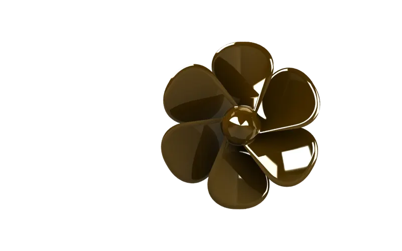
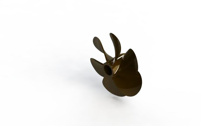
There can be one, two or three propellers. It is the most important part of the ship without which a ship can't move. So, the main function of propeller is to propel the ship in the forward direction by producing thrust on water. Its working principles are Newton's third law of motion and Bernoulli's theorem.
COMMANDS USED TO MODEL
In Sketch
- Spline
- Circle
- Line
In Features
- Revolved Boss/Base
- Lofted Boss/Base
- Extruded Cut
- Reference Plane
- Circular Pattern
- Fillet
MODELLING PROCEDURE
- The center portion of the Propeller was sketched and revolved using Revolved Boss/Base.
- Then the Blades were created using the Reference Plane, Lofted Boss/Base and Fillet.
- Then the remaining five blades were created by using Circular Pattern.
- Then the center circular portion was removed using Extruded Cut option.
- Finally the part was saved by adding the proper appearance.
GARAGE DOOR
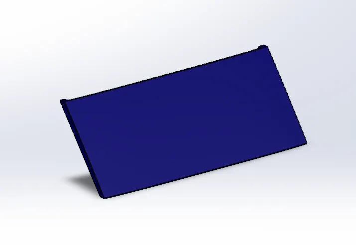
A garage door is a large door on a garage that opens either manually or by an electric motor (a garage door opener). Garage doors are frequently large enough to accommodate automobiles and other vehicles.
COMMANDS USED TO MODEL
In Sketch
- Line
- Spline
- Circle
- Text
In Features
- Extruded Cut
- Reference Plane
- Fillet
- Shell
- Mirror
MODELLING PROCEDURE
- The solid body split while creating the Hull was imported to model the Garage Door.
- By using the Extruded Cut the Chamfered face for the door was created.
- Then by using the shell feature the solid body for our garage door was created and proper fillets were applied.
- Then the door holders on both sides were created using Extruded Cut.
- Then the second half of the Garage Door was created using Mirror tool after applying the required fillets.
- Then the text over the garage door “HAKUNA MATATA” was created using the text option in sketch feature.
- Finally the part was saved by applying proper appearance.
RADARMAST
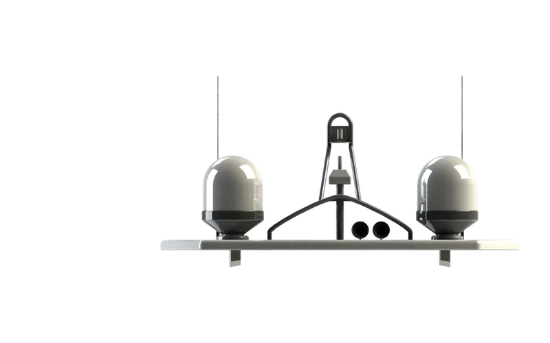
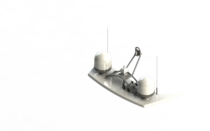
A mast is a vertical ship structure mounted on top of bridge and forward of the forecastle towards the ship’s bow. It accounts for the support platform for the ships derrick and hold necessary equipment’s such as radars, navigation light and ships horn in case of foremast. They are made of high tensile steel with added rigidity based on the size of derricks it holds. Other than that a ships main mast is also used to hoist ships flag
.
COMMANDS USED TO MODEL
In Sketch
- Sketch Picture
- Line
- Spline
- Rectangle
- Arcs
In Feature
- Extruded Boss/Base
- Lofted Boss/Base
- Revolved Boss/Base
- Swept Boss/Base
- Reference Plane
- Projected Curve
- Fillet
- Mirror
- Dome
- Shell
MODELLING PROCEDURE
- The first half of the Radar was Modelled with the help of blueprint and then the other half was mirrored with the help of Mirror tool.
- The body of the Radar was created using Extruded Boss/Base and Revolved Boss/Base.
- The antenna for the radar was also created using the Extruded Boss/Base.
- The lamp stand along with the connecting rod were created using the Swept Boss/Base and Mirror tool.
- The lamp was created by using the projected curve and then the curve was swept using swept boss/base.
- The horns were created using the Revolved Boss/Base, Dome and Shell.
- Then the fillets and chamfers were applied wherever necessary.
- Finally the part was saved by applying appropriate appearances.
FRONT SEAT
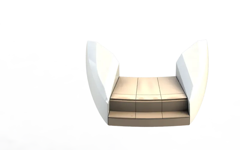
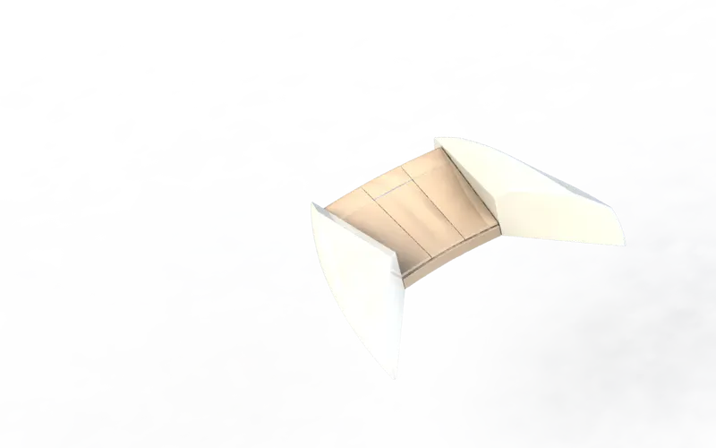
Front seats feature two connected seats that are built back-to-back from one and other. They have a built-in storage unit underneath them. Lounge seats can also fully recline right back to make it easier for you to kick your feet up and get more comfortable. The front seat in our model was placed before the superstructure and also it has sun pads to rest on it. Sun pads are a great way to reclaim lost space on our boat.
COMMANDS USED TO MODEL
In Sketch
- Sketch Picture
- Line
- Spline
- Circle
- Arcs
In Surfaces
- Extruded Surface
- Lofted Surface
- Trim Surface
- Filled Surface
- Knit Surface
- Swept Surface
- Revolved Surface
In Features
- Extruded Cut
- Revolved Boss/Base
- Chamfer
- Fillet
- Mirror
- Dome
MODELLING PROCEDURE
- The Front seat of the Yacht was also created with the help of Blueprint.
- The first half was modelled and the other half was mirrored using Mirror tool.
- The front seat was placed before the Superstructure facing the Water Feature of the Superstructure and the back end must be placed on the bow of the Yacht.
- The body of the Front Seat was modelled using Swept Surface, Extruded Surface, Filled Surface, Lofted surface and the unwanted part was removed using Trim Surface.
- Then the four Rest Beds were created using Extruded Boss/Base and the dome was created over the face of the beds separately.
- Then the required fillets and chamfers were created with extruded thin surfaces.
- Finally the part was saved by adding proper appearances.
MIDDLE SEAT
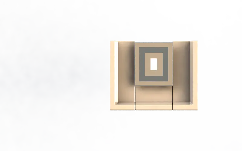
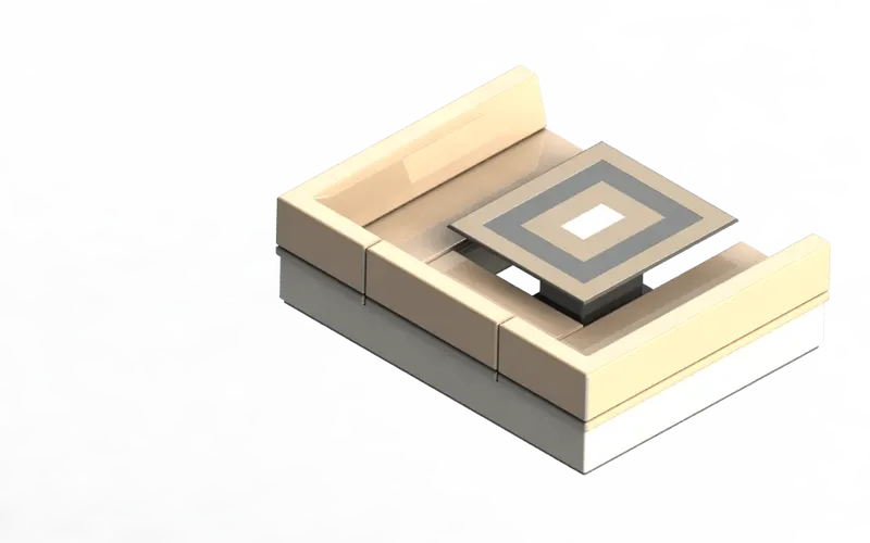
The middle seat in our model was placed just behind the superstructure. It is provided with a luxury table to dine out. It can also be used to have casual meetings with co-passengers.
COMMANDS USED TO MODEL
In Sketch
- Sketch Picture
- Line
- Rectangle
In Features
- Extruded Boss/Base
- Chamfer
- Fillet
- Mirror
- Reference Plane
MODELLING PROCEDURE
- The Middle Seat was created using the Extruded Boss/Base and by applying the Chamfers and fillets as required.
- All the surfaces created must be Knitted together by using the Knit Surface option.
- The Dining Table was also created using Reference Plane, Extruded Boss/base, Off-set, Chamfers and Mirror.
- Then the second half of the Middle Seat must be Mirrored symmetrically.
- Finally the part was saved by applying the proper appearances.
REAR SEAT
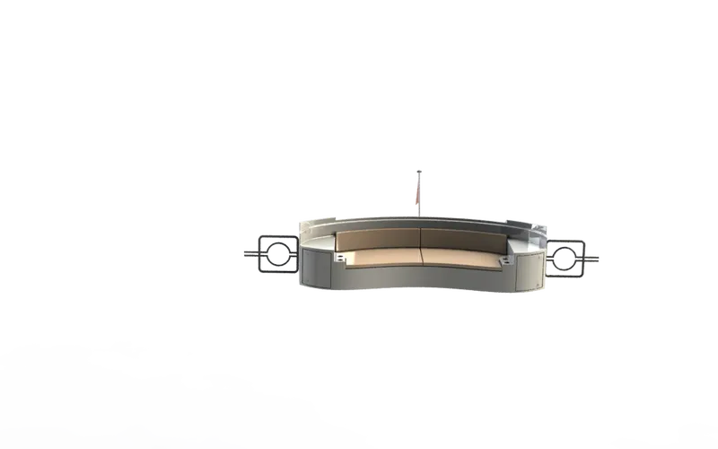
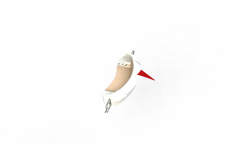
The rear seat was placed at the end of the deck surface. The rear seat consist of locker racks and steel doors for our stairs. The flag was also placed behind the rear seat since it’s the end part of our yacht. To have a nice view from the yacht while having a drink the rear seat was also provided with a slots to rest the glass or mug.
COMMANDS USED TO MODEL
In Sketch
- Sketch Picture
- Line
- Spline
- Circle
- Arcs
- Rectangle
In Surfaces
- Swept Surface
- Extruded Surface
- Off-set Surface
- Filled Surface
- Knit Surface
- Ruled Surface
- Lofted Surface
In Features
- Reference Plane
- Extruded Boss/Base
- Revolved Boss/Base
- Fillet
- Mirror
MODELLING PROCEDURE
- The main body of the Rear Seat was modelled using Swept Surface, Off-set Surface and the remaining portion was trimmed using Trim Surface tool.
- By using the Reference Plane the Seats were created with the help of Lofted Surface, Surface Trim and Extended Surface.
- The Flag Post was created using Revolved Boss/Base and the Flag was created by drawing the required 3D sketch and then the 3D sketches were lofted to form the Flag.
- The Tail Lamps were created by using Extruded Boss/Base, Fillets and Mirror tool.
- The Steel Gates For Stairs was designed by using the reference plane and the Swept Surface.
- To remove the gaps the all the Surfaces must be Knitted together using Knit Surface.
- The required fillets and chamfer were created before mirroring the second half using Mirror tool and after mirroring the uncreated areas were filleted again.
- Finally the part was saved by adding appropriate appearances.
ASSEMBLY
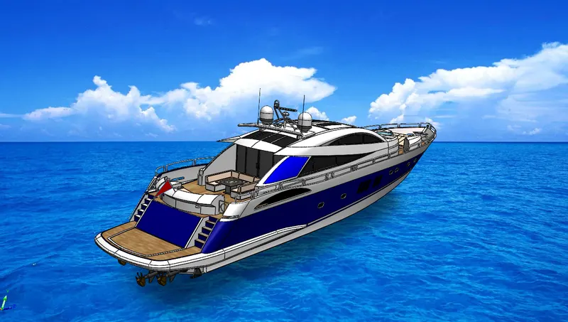
assembly of all parts is done in sldsm files. mates, insert and mirror are most usefull and applicable commands in assembly.
ASSEMBLY COMMANDS
- Smart Mate - A Smart mate is an assembly mating relation that is created automatically.
- Mate - A mate is a geometric relationship, such as coincident, perpendicular, tangent, and so on, between parts in an assembly.
- Mate group - A mate group is a collection of mates that are solved together. The order in which the mates appear within the mate group does not matter.
- Sub-Assembly - A sub-assembly is an assembly document that is part of a larger assembly. For example, the steering mechanism of a car is a subassembly of the car.
- Insert Components - We can insertmultiple instances of the group of components without closing the Property Manager.
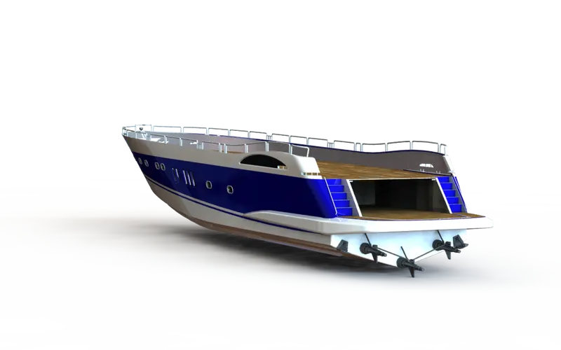
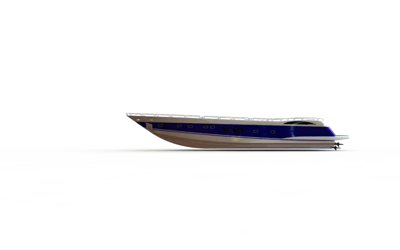
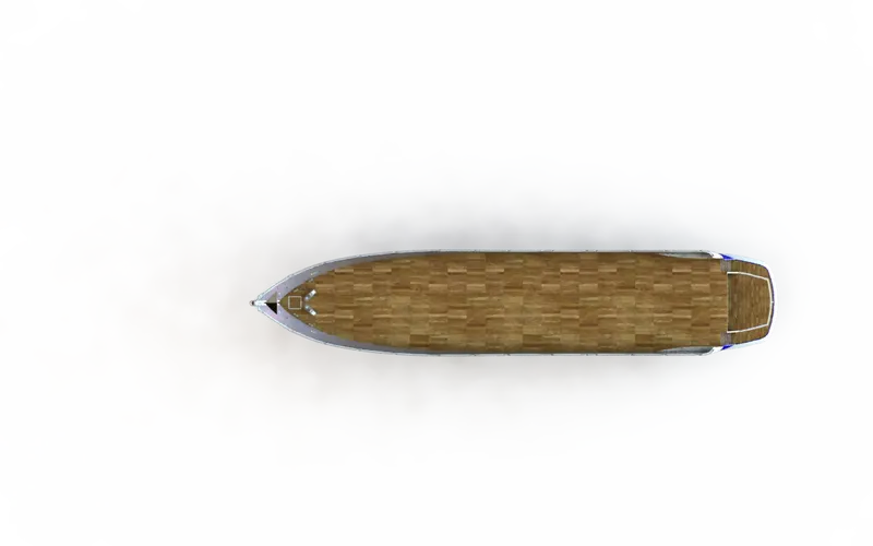
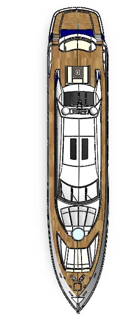
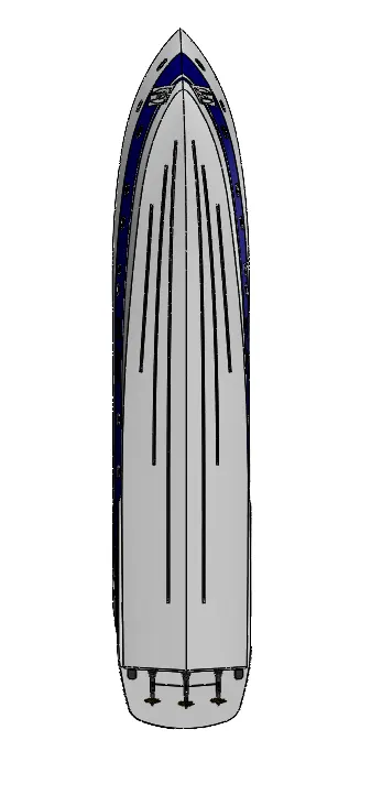
Top view and bottom view
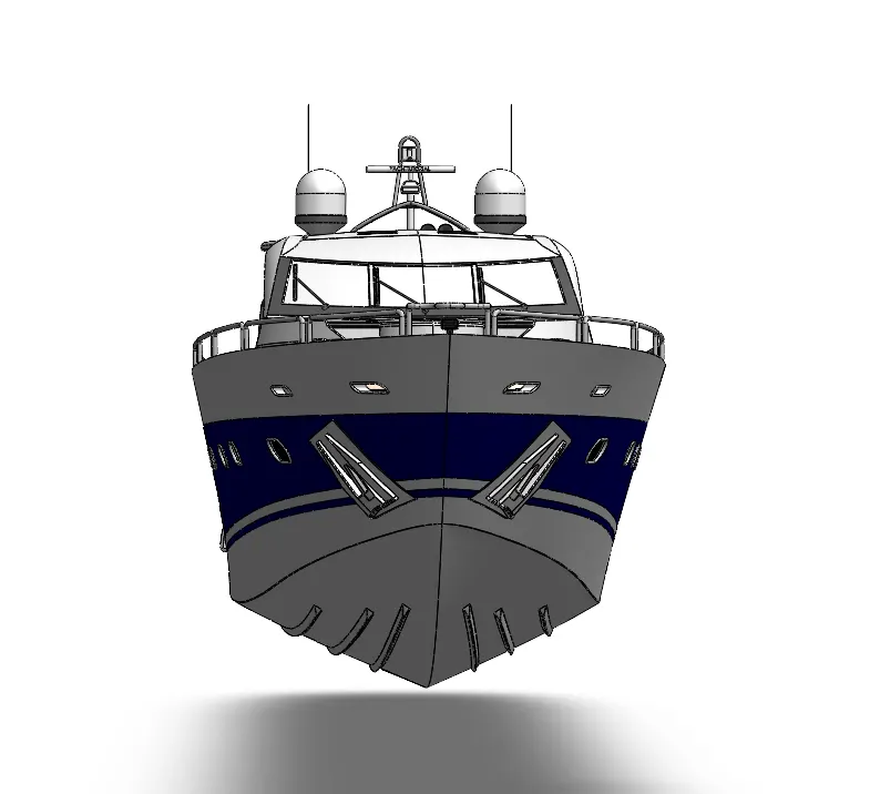
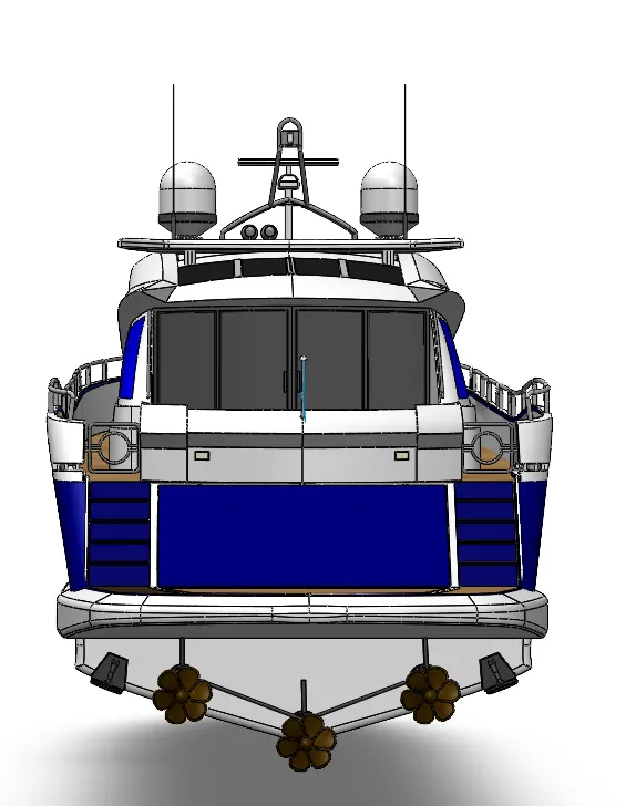
front view and back view
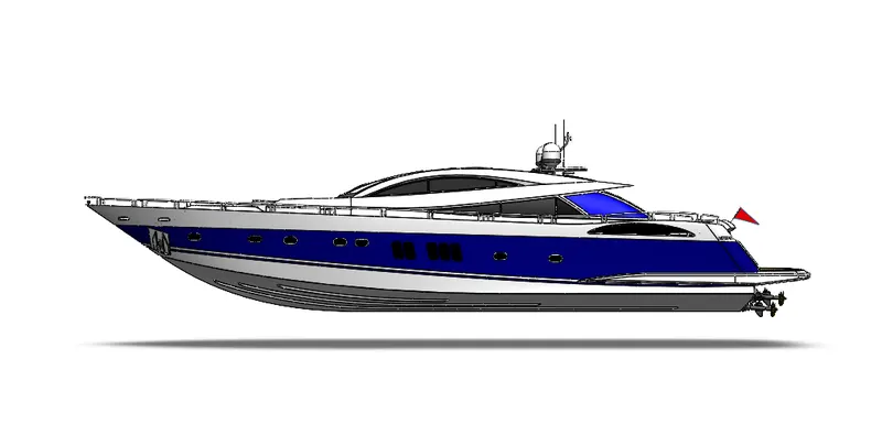
side view and iso view
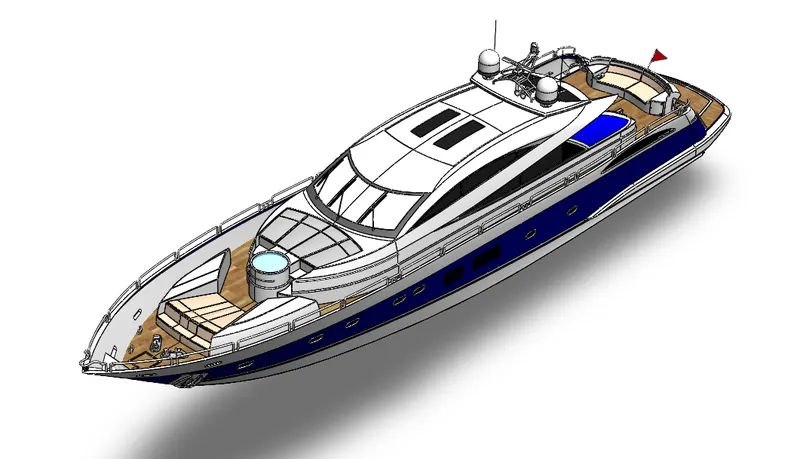
Assembly Procedure
- Import all the parts manually by using Insert Components option.
- Then fix the Hull part by applying the coincident mate to the Top, Right and Front planes of the Assembly and Hull respectively.
- Then for each part apply the necessary mates required by the Blueprint using Coincident mates, Angle Mates, Distance mates etc.
- Advanced mate was also used wherever required.
RENDERING
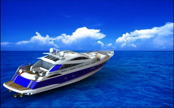
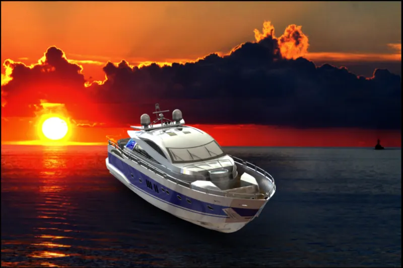
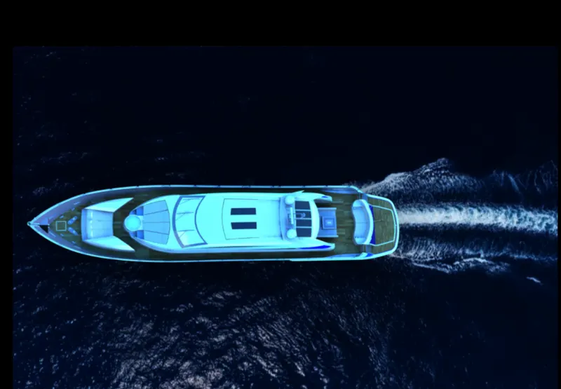
Rendering of the Solidworks model is done using PhotoView 360 and Solidworks Visualize.
PhotoView 360 is a visualization and rendering solution included with SOLIDWORKS. Providing a highly interactive environment for viewing designs as well as for creating photo-realistic renderings it can be used to showcase our designs.
- Environments - Environments can be looked upon as backdrops and can be applied in a similar manner as the appearances are applied to faces or parts
- Appearances - There are a wider range of appearances in PhotoView 360 than in SolidWorks. If we wish to change an appearance just drag and drop the chosen appearance onto the part and it will replace the existing one.
- Lighting - Lights may be added in the same way a photographer adds lights when taking photographs. PhotoView 360 uses the same lights as SolidWorks but also uses lighting from the rendering environment or scene. PhotoView 360 has the sophistication to trace light rays and reflections.
- Scenes - Each SolidWorks model is associated with a PhotoView 360 scene, for which you can specify properties such as environments and backgrounds. Scenes help to put products in context.
- Decals - Images, such as company logos, can be applied to models.
- Output - The rendered output from PhotoView 360 can be viewed on the screen, or saved to a graphics file.
- Options - PhotoView 360 has its own options. Options allow you to customize the PhotoView 360 settings to reflect your preferences. Options are divided into Output Image Settings, Render Quality, Bloom, Contour Rendering and Direct Caustics.
day time yacth rendering : camera view
suset yacht rendering : camera view 2
top view crushing
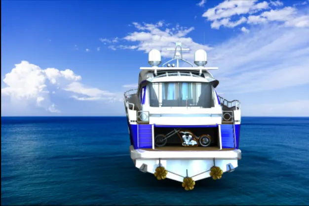
backview garage door
conclusion
I learned advance surface modelling and 3d modelling in this project. i also learned concept of yacth design in proffestional way and i learned more about realistic 3d rendering with decals and camera view.