Photo Realistic Rendering
3D modeling and rendering of American chopper
Aim and objective
- To learn about drafting and 3d modeling of every part of American chopper using sketches and features command in Solidworks.
- To learn about the different features of Assembly and how parts are assembled in Solidworks assembly.
- To create photorealistic 3d modeling and rendering of American chopper in rendering tools of Solidworks.
Introduction
- American chopper is a custom motorcycle design with low ground clearance, modified steering angle, and lengthened fork for strength out appearance.
- The design concept related to sketching, part modeling, assembly, and 3d realistically model rendering is learned in this project.
- The whole project starts with part modeling of different components of chopper bike assembly.
Design methodology with flow chart
- Part modeling
The sketch
features
direct editing and other commands
2. Assembly
Insert component
mates
component pattern
- 3d rendering
Appearance
Preview window
Camera
Decals
Spotlight
Point light
Directional light
Scene creating
Final rendering
Part modeling
- Part modeling is the first step of 3d modeling and assembly, in which we model a different component of chopper assembly in Solidworks part files.
- the part modeling starts with a constrained sketch and applies different features for 3d modeling according to the sketch and our plan for modeling.
The component modeled in chopper bike assembly is given below. - Transmission belt
- Kickstand
- Front fender
- Rear fender
- Oil tank
- Gas tank
- Engine
- Chassis
- Chain
- Pedal
- Front-wheel rear wheel
1. Transmission belt
- The Transmission belt is used to transmit power from the engine to the gearbox.
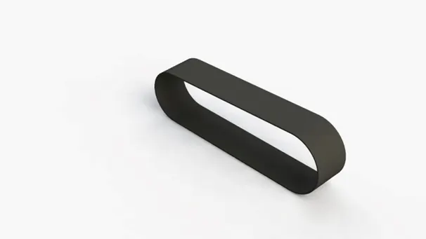
features used to create transmission belt
- Sketch
- Extrude
- Fillet
- Appearance
Sketch
The sketch is drafting command is used and create 2d sketches in different planes and faces on the concept of engineering drawing. We create sketches according to our design consideration and final 3d modeling of the assembly part. The part is followed and made by different features like boss extrude, sweep, loft, and revolve. These are the main command of 3d modeling in Solidworks to create sketches. Initially, we create a sketch on three of the one main plane of part modeling and start the sketch.
Extrude
Extrude is command is a feature in Solidworks which used to convert 2d plane sketches to 3d models.
Fillet
Fillet/Round creates a rounded internal or external face on the part. You can fillet all edges of a face, selected sets of faces, selected edges, or edge loops.
procedure to complete belt transmission
Model is created by front plane 2d sketch with proper dimension and constraint with fully define sketch
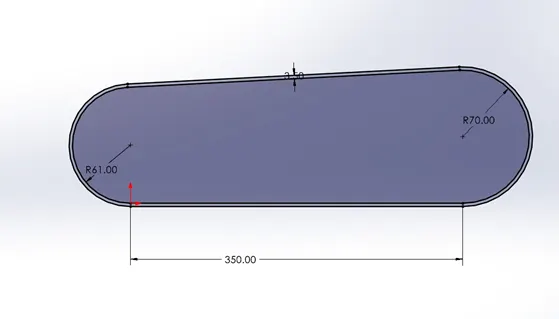
The given sketch is a fully defined sketch and used commands like offset entities to make the sketch easy to draw and save sketch time.
boss extrude command is used after the fully defined sketch is created.
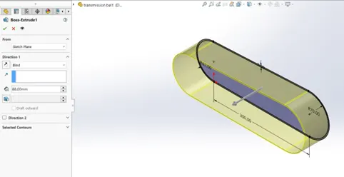
how I used boss extrude command to manage to build a 3d model from sketch plane. we can use different options as our requirement.
the last command used to complete the overall model is the fillet and from that model is complete.
2. kickstand
This model is made to give support to motorcycles when it's put on stands for stationary.
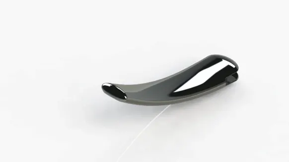
features used to create a kickstand
- Sketch
- loft
- Dome
- Cut extrude
- Extrude boss
- Split
- Fillet
- appearance
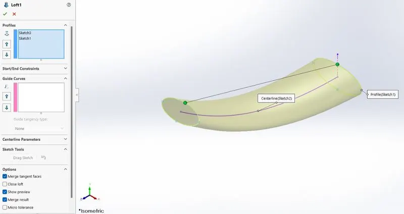
Loft
The loft tool is one of the many Solidworks that help you create smooth and organic shapes. It creates a shape by making transitions between multiple profiles and guides curves thus allowing you to create complex geometry with a single tool.
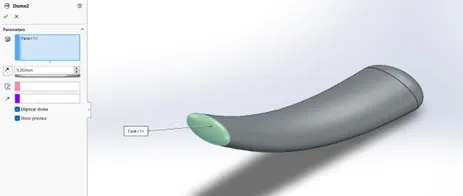
Dome
Dome is a time-saving feature, allowing for domes to be created without the need for a sketch or revolve. Domes can be concave or convex, and they can be applied to various surfaces.
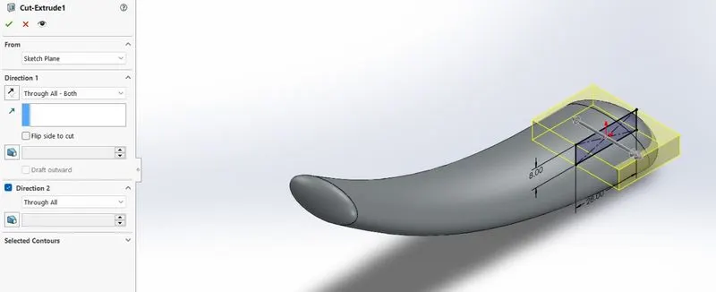
Cut Extrude
Extrude cut is a feature that helps to remove materials from the 3D model. It is just the opposite of to extrude boss/base feature because it cuts a sketch profile while extruding. You can cut in both directions and are mainly used for creating holes, channels, slots, etc.
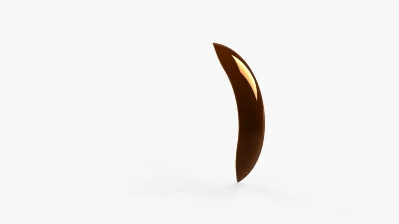
Spilt
The split feature is an extremely useful tool when designing using multi-body part techniques in SOLIDWORKS. Take a look at how the tool functions and what we can do with the bodies once they have been split. The split feature is an extremely useful tool when designing using multi-body part techniques in SOLIDWORKS.
3. front fender
The front fender is a part mounted on the fork above the front wheel to protect the rider.
features used to create a front fender
- Sketch
- Offset entities
- Trim entities
- Revolve
- Mirror entities
- Spilt
- appearance
Trim entities
The Trim Entities tool is mainly used for removing unwanted parts or portions from your design sketch. For trimming, you must have coincident sketch parts with another. The Sketch Trim Entities also consist of the “Extend Entities” tool, which helps to extend or adjust the lines. The trimming is like removing unwanted parts using scissors.
Revolve
Revolved Boss or Base is a SolidWorks feature tool that is used to create a solid 3D model around an axis. You can resolve the sketch around an axis to add materials to it. You can access revolved boss/base from both the command manager and menu bar.
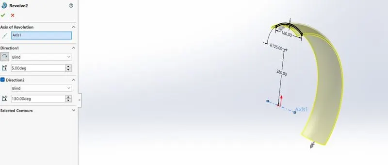
here I used command to give a revolve shape from the reference axis and build the model by revolving in the front fender
Mirror entities
When you create mirrored entities, the SOLIDWORKS software applies asymmetric relation between each corresponding pair of sketch points (the ends of mirrored lines, the centers of arcs, and so on). If you change a mirrored entity, its mirror image also changes. Conditions for 2D Sketches on 3D Sketch Planes.
4. Rear fender
The function of the rear fender is the same as the front fender but it is mounted above the rear wheel.
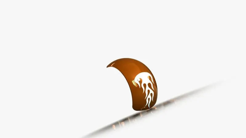
features used to create a rear fender
- Sketch
- Offset entities
- Trim entities
- Revolve
- appearance
Appearance
An appearance defines the visual properties of a model, including color and texture. Appearances do not affect physical properties, which are defined by materials.
5. Oil tank
The oil tank is one of the parts of the chopper. An oil tank is used to store the oil required to run the engine. The oil tank is the hollow one. The thickness of the oil tank is given by 3mm in our chopper.
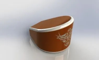
features used to create an oil tank
- Sketch
- boss extrude
- combine
- fillet
- shell
- appearance
Combine
The Combine feature in SOLIDWORKS is a great tool used most often in surface modeling as it allows you to take molds of created parts for mold operations. It is also useful when creating negative spaces for a part to fit into to show where an item might reside in an assembly. How to use Combine Feature To combine, open your base component.
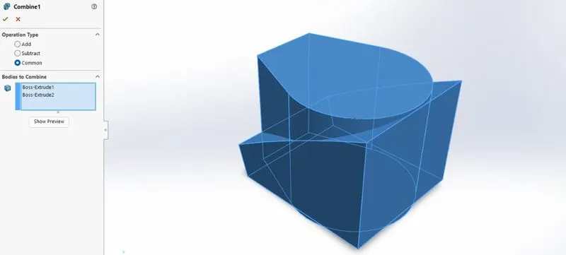
here I used combine common command two select two different bodies of boss extrude from the different plane and merge it both by the common combine and get a smooth surface of what we want to create, this is a very useful tool in direct editing.
Shell
The shell tool hollows out a part, leaves open the faces you select, and creates thin-walled features on the remaining faces. If you do not select any face on the model, you can shell a solid part, creating a closed, hollow model which I do in this model.
6. pedal
The pedal is the external part attached to the chassis. This part is used to give to place a leg on top when the rider rides a
motorcycle.
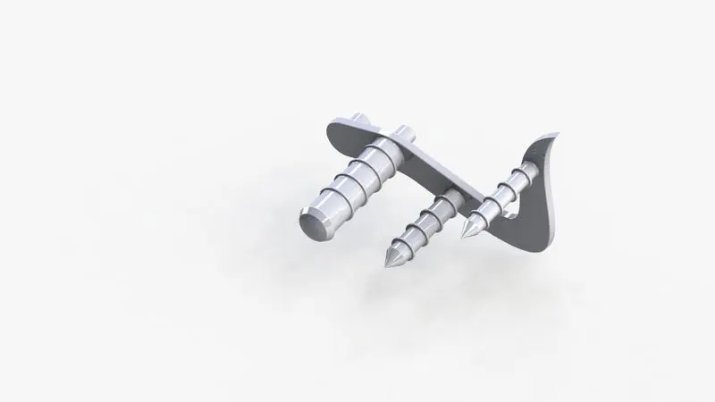
features used to create a pedal
- Sketch
- boss extrude
- combine
- fillet
- shell
- chamfer
- dome
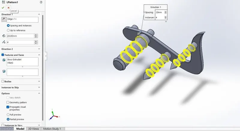
- linear pattern
- appearance
Chamfer
SolidWorks chamfer tool is one of the useful tools in Solidworks cad software, which helps to cut (45-degree angle with the normal surface) or make edges or corners (vertex) of 3D model straight.
Linear pattern
The linear pattern is a very useful command feature that helps to create the same features, faces and bodies to be copied in a linear direction with spacing and instance or also by reference.
7. Front-wheel
Front-wheel is the is a circular block made of steel and alloy material. On the top of the wheel, the tire is covered. This wheel is mostly designed for extra steering angle for riders who ride on a motorcycle.
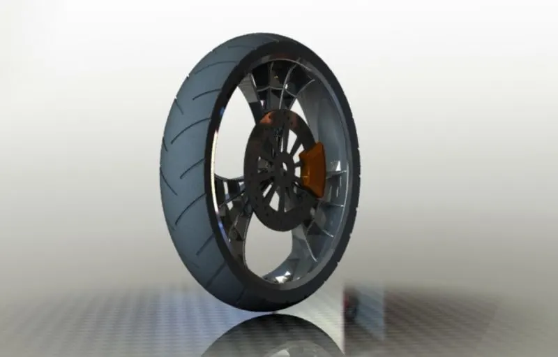
features used to create a front wheel
- Sketch
- boss extrude
- revolve
- combine
- trim
- cut extrude
- revolve cut
- circular pattern
- fillet
- chamfer
- appearance
- offset entities
Circular pattern
The circular pattern has the same function as the linear pattern, the difference is circular pattern is applied with reference axis to given angular space by equal spacing or instance spacing and given no of bodies to copy.
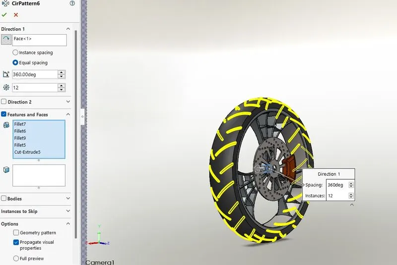
In this model, we used a circular pattern three times. at last, we create surface cut extrude and fillets commands to copy in a circular pattern with equal angle space.
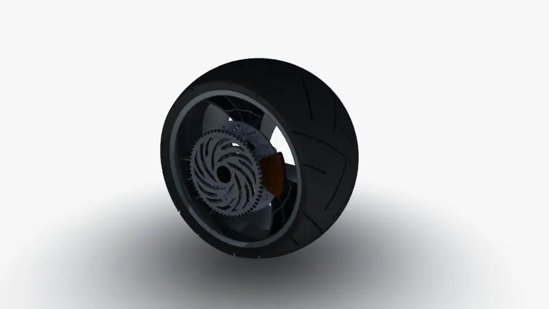
8. rear wheel
- Rear-wheel is a circular object which revolves around with given axis and is fixed below a vehicle.
- This wheel has a larger width and minimum radius as compared to the front wheel which gives good strength to the vehicle and increases the weight transfer with the ground surface.
- A disk and sprocket are attached with a rear wheel.
- The chain is connected with a sprocket of the rear wheel and sprocket of the gearbox which is attached to the engine by belt drive transmission and how this way we get power and rotation in the rear wheel.
features used to create a rear wheel
- Sketch
- boss extrude
- revolve
- combine
- trim
- cut extrude
- revolve cut
- circular pattern
- fillet
- chamfer
- appearance
- offset entities
- linear pattern
- planes
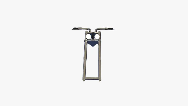
9. front fork
- The fork can easily understand as simply large hydraulic shock absorbers with internal coil springs. They allow the front wheel to react to imperfection on the road while isolating the rest of the motorcycle from that motion.
features used to create a front fork
- Sketch
- boss extrude
- revolve
- combine
- trim
- move/copy body
- convert entities
- mirror
- fillet
- curve(project curve)
- appearance
- split
- sweep
- planes
- dome
Move/copy body
Move/copy body is used to move/copy the body by one place to other places in the fork.
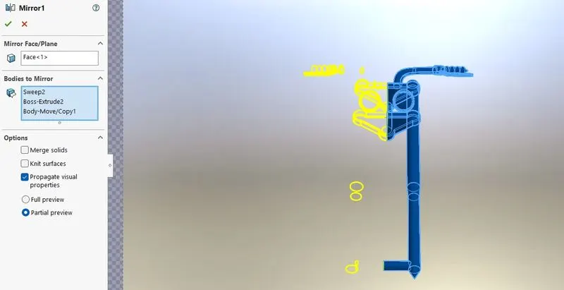
Mirror
A mirror is a virtual object in Solidworks that can be used to create a reflection of an object. You can use Mirror to create a copy of one or more features, mirrored about a face or a plane. In parts, you can mirror faces, features, and bodies. In assemblies, you can mirror assembly features.
Project curve
A project curve is the kind of 3d curve projected on the basis of the two different 2d sketches.
Sweep
A sketch profile creates a sweep by moving a 2D profile along a 2D or 3D sketch path.
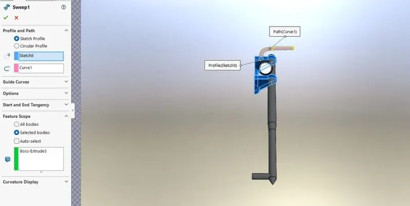
in this model, we used a projected 3d path and plane profile to create a smooth 3d sweep handle.
10. chassis
A motorcycle’s chassis or frame forms its skeleton. All the components of a motorcycle, like the suspension, wheels, fuel tank, seats, handlebars, etc, are attached to this base structure which lends a motorcycle its strength and ability to handle well.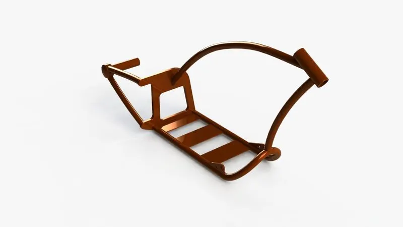
features used to create a chassis
- Sketch
- boss extrude
- combine
- trim
- cut extrude
- convert entities
- mirror
- fillet
- curve(project curve)
- appearance
- split
- sweep
- planes
- dome
11. Engine
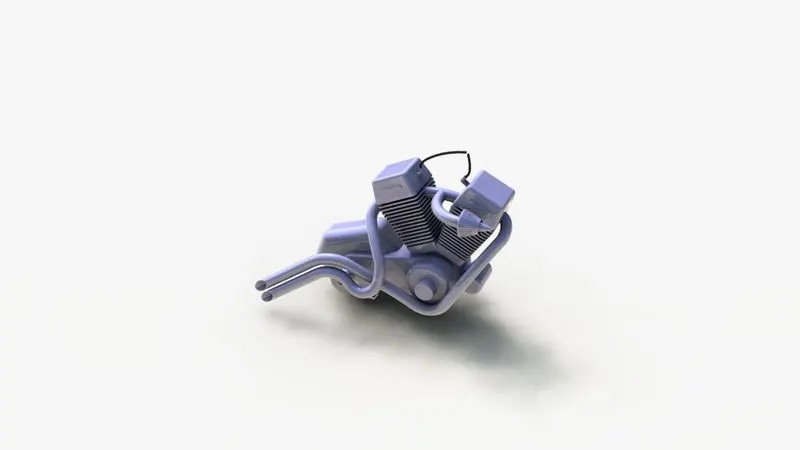
A motorcycle engine is an engine that powers a motorcycle. Motorcycle engines are typically two-stroke or four-stroke internal combustion engines, but other engine types, such as Wankel’s and electric motors, have been used.
In our vehicle, we build a model of a V2 four-stroke engine for high performance and good power with two exhausts pipe.
In our engine design, we transfer engine power from the rotational shaft to the gearbox by a belt drive and it further transfers to the rear wheel of the vehicle by a chain drive and how this way vehicle power transmission work.
features used to create an engine
- Sketch
- boss extrude
- combine
- trim
- cut extrude
- convert entities
- mirror
- fillet
- project curve
- appearance
- split
- sweep
- planes
- dome
- revolve
- composite curve
- circular pattern
- linear patter
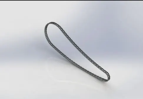
12. chain
A chain drive is a way of transmitting mechanical power from one place to another. It is often used to convey power to the wheels of a vehicle, particularly bicycles and motorcycles. The gear is turned, and this pulls the chain putting mechanical force into the system.
features used to create a chain model
- Sketch
- boss extrude
- blocks
- trim
- curve pattern
- fillet
- appearance
Curve driven pattern
The Curve Driven Pattern tool allows you to create patterns along a planar or 3D curve. To define the pattern, you can use any sketch segment, or the edge of a face (solid or surface), that lies along the plane. You can base your pattern on an open curve, or on a closed curve, such as a circle.
Like other pattern types, such as linear or circular, you can skip pattern instances, and patterns in one or two directions.
blocks
You can make, save, edit, and insert blocks for drawing items and sketch entities that you use often, such as standard notes, title blocks, label positions, and so on. You can attach blocks to geometry or to drawing views, and you can insert them into sheet formats.
To make blocks:
- Create a sketch
- Click make a (Tools> Block > Make)
- Select a sketch entity you want to make a block for block entities.
- Right-click on the block tool
- Repeat this step for each entity.
- Save all blocks in SLDBLK files.
- Now we used this block for our curves of the chain.
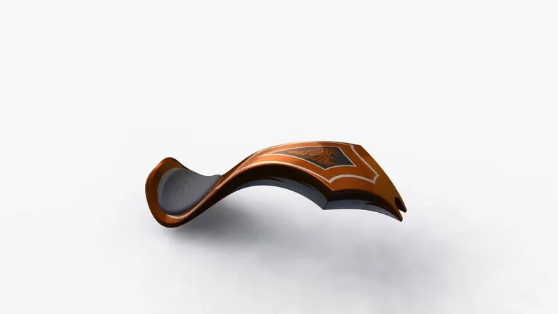
13. Gas tank
Gas tanks are used to store the gas. To give the gas to the engine when required.
features used to create a gas tank
- Sketch
- surface sweep
- surface trim
- surface loft
- boundary surface
- mirror
- curve
- plane
- surface knit
- split line
- surface extrude
- fillet
- cut sweep
- shell
- split
Loft surface.
The aloft feature is an important tool for (surface) modeling in SolidWorks. The loft feature creates a shape by making transitions between multiple profiles and guide curves. This tool is very valuable for modeling complex surfaces.
Sweep surface.
Sweep surfaces are surfaces that are generated from a section curve positioned along a path.
Filled surface.
The filled Surface feature constructs a surface patch with any number of sides, within a boundary defined by existing model edges, sketches, or curves, including composite curves. You can use this feature to construct a surface to fill a gap in a model.
Surface trim.
Primarily used to cut away material from a surface, and provide two modes: standard and mutual.
Surface extrude.
To use Extruded Surface command in Solidworks, you need to have a proper sketch to extrude. Unlike the normal Extrude command, this command does not create 3D solid bodies, it creates surfaces by extruding sketches. After entering into the ‘Surface Extrude’ command, select the proper sketch entity as shown by the blue arrow above.
Surface knit.
Use the Knit Surface tool to combine two or more faces and surfaces into one. Create a solid body when the knit surfaces form a closed volume or leave as a surface body.
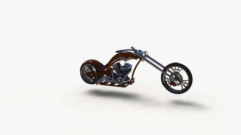
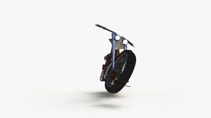
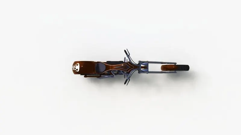
American Chopper assembly
- Initially, the chassis is inserted in the assembly by using insert parts in the option. After that, the part is inserted into the assembly environment and clicked ok to fix the chassis.
- After that, the other parts of the chopper are inserted into the assembly and give possible mate conditions.
features used to assemble chopper
- mates
- insert part
mates
mates in Solidworks are in 3 categories: standard mates, mechanical mates, and advanced mates. to use mate you should go to assembly mode. select the parts you wanna mate them and select a logical mate from the mate icon in the assembly toolbar or from inset> mate.
As we add mates, we define the allowable degree of freedom of every part in a given assembly, there is a total of 6 degree of freedom. three linear and 3 rotational.
front view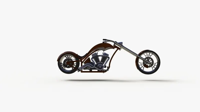
side view
Top view
camera view
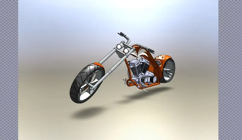
iso view
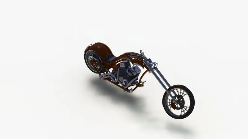
Rendering with scenario
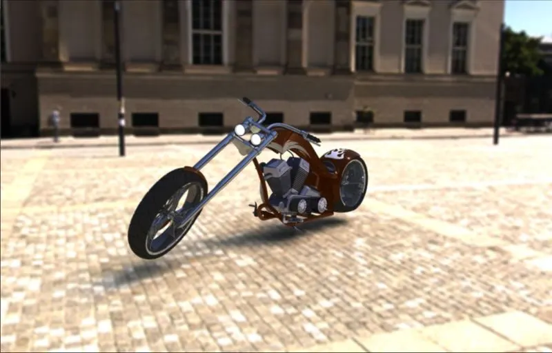
PHOTOVIEW 360 is a rendering package included in both SOLIDWORKS Professional and SOLIDWORKS Premium. It allows us to take our 3D designs and quickly turn them into a photo-realistic image. This allows us to show how good our products are to existing and potential customers.
Rendering is done in two ways:
- photoview 360
- solidworks visualize
Conclusion
- I learned 3d modeling of all different parts and the features of Solidworks part modeling with fully define sketch with proper constraint and dimension.
- I learn part assembling in Solidworks assembly by using of chopper bike assembly and learned about different mates and their mirror commands.
- I learn about 3d realistic rendering of chopper bike assembly in Solidworks photoview 360.