Roof Design
Aim: Design of the front roof rail, rear roof rail, and bow roof for the roof of the vehicles with the help of the given skin data of the roof according to snow load condition and hear distortion criteria.
Objective:
- Study different type of the roof available in the market.
- Study about the heat distortion criteria to adjust the position of bows and center roof rail.
- Study about snow load conditions to check the strength of the roof according to bows positions.
Theory:
Roof: An automobile roof or car top is the portion of an automobile that sits above the passenger compartment, protecting the vehicle occupants from sun, wind, rain, and other external elements.
- Convertible roofs. Roof modules. Roof modules.
- Hardtops.
- Sunroofs.
- T-tops.
- Targa tops.
- Vinyl roofs
Design Consideration and criteria:
1.Roof:
a.We are making the hardtop type of roof from the given master section so we are not adding any reinforcement for the central roof rail.
b.We are adding the flanges to all sides of the roof for spot welding of the front roof rail, central roof rail, rear roof rail, and bows.
c.The length and angle of the flange are decided based on the visibility criteria and according to the draw angle required for manufacturing the sheet metal.
d.The thickness of the roof is decided 0.75mm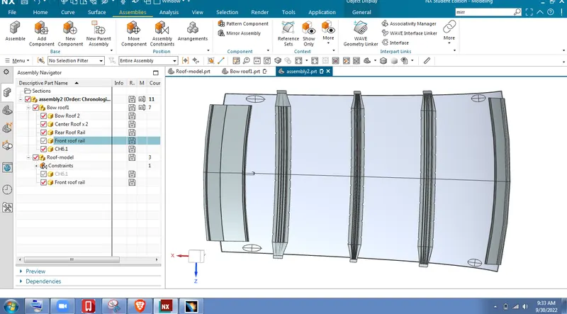
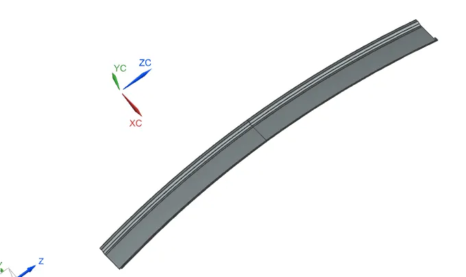
2.Front roof rail:
a.The front roof rail is used as the reinforcement to the roof surface to increase the strength and also used to mount the brackets for some features such as room lamp or map lamp and rear mirror.
b.The depth of the front roof rail is decided based on the visibility criteria line decided for the driver visibility.
c.The width of the front roof rail is decided in such a way that there should be enough headroom clearance between the head of the driver and the end surface of the roof rail to avoid injuries to the person.
d.At the front side we are doing spot welding and on the rear side of the front roof rail, we are using mastic points to join it with the roof surface.
e. The minimum radius for the fillet at edges is 3mm
3.Rear roof rail:
a.The rear roof rail is used as the reinforcement to the roof surface at the rear side.
b.The joining method used for this rail is the same as that of the front roof rail.
c.The minimum radius for the fillet is 3mm.
4.Bows:
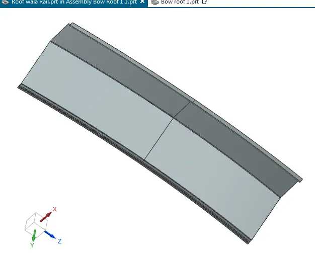
a.We are making two bows one is in between the front roof rail and central roof rail and another is in between the central roof rail and rear roof rail.
b.Both ends of the bow are joined to the roof outer flanges by the spot welding and the inner sides of the bow are joined to the inner surface of the roof with the help of mastic points.
c.The minimum radius of the fillet is 3mm.
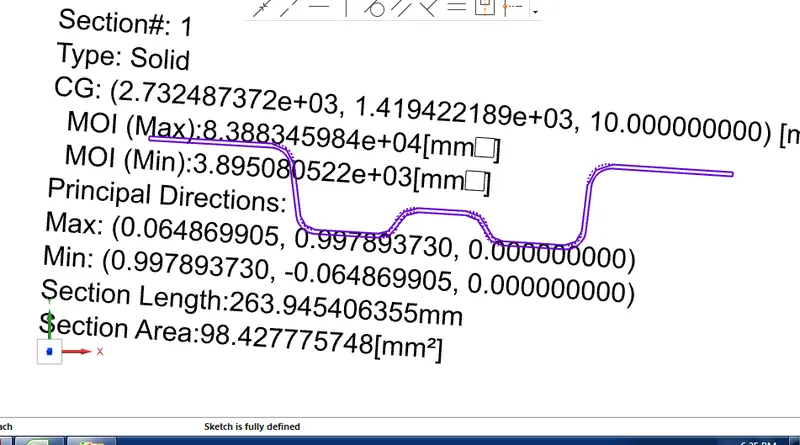
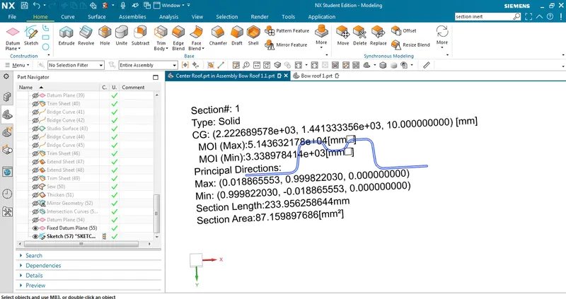
d.The cross-section of the bow is made in such a way that we should get the maximum value of the minimum moment of inertia at which the bow fails
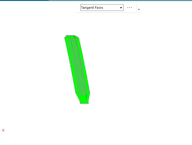
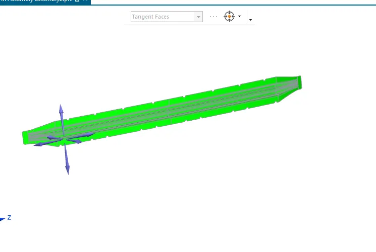
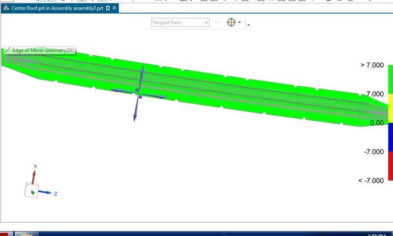
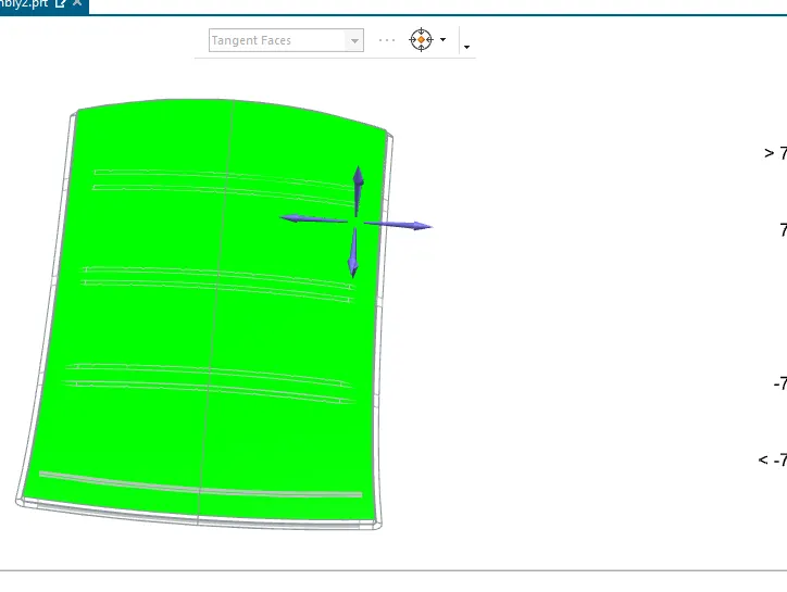
Draft Analysis of parts
5.Heat disntortion criteria:
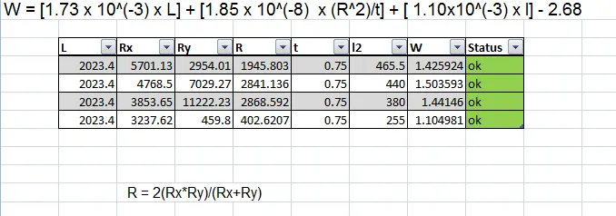
In this criteria, we check the heat distortion capacity of the roof at higher temperatures with the fixed load on it. So when the surrounding temperature is high and the roof is loaded with some weight on it then if the roof is deformed it fails, so to calculate whether the roof deform or not, according to the position of the bow we do these calculations as follows
The formula for the heat distortion criteria:
W=1.73⋅10−3∗L+1.85⋅10−8⋅(R2t)+1.10⋅10−3⋅I−2.68W=1.73⋅10-3∗L+1.85⋅10-8⋅(R2t)+1.10⋅10-3⋅I-2.68
whereas,
L= Length of the roof without including ditch length
R = Roof curvature
R = 2⋅Rx⋅RyRx+Ry2⋅Rx⋅RyRx+Ry
Rx=Rx=Curvature of the roof in X-direction
Ry=Ry=Curvature of the roof in Y_direction
t = thickness of the roof
I = Distance between the two consecutive reinforcement added(Bow roof span mm)
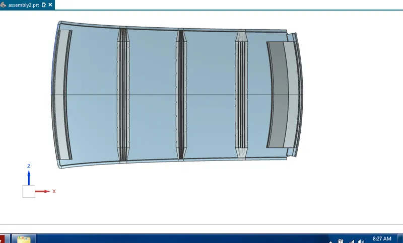
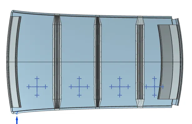
Steps to calculate the Heat distortions as follows:
1.First we offset the center y-axis line to 300mm distance apart from it represented as (-3Y to 3Y red line).
2.After that we offset this -3Y to 3Y to 100mm offset each side represented with the green line.
3.We draw the vertical red line at the center of the two consecutive bow rood span. Next, we offset this red line to 100 on each side.
4. Now we have three horizontal lines and three 12 vertical lines we take the intersection points of the vertical red line with three horizontal lines and a horizontal red line we take the intersection of the vertical lines with that line.
5.After getting all the points we project these points on the roof surface and draw the three points curve along the x-axis point to get the radius of curvature of Ry and along y-axis points to get the radius of curvature of Rx.
6. Snow load condition:
This snow load condition calculation is done to check the strength of the roof when there is dead weight on the roof. As we know that in some regions we have snowfalls so when snow falls on the roof then this act as dead weight because in some the rate of snowfall is more so the roof should sustain this dead weight for that we do this calculation to check the position of the bow and its sectional area.
The formula for snow load condition:
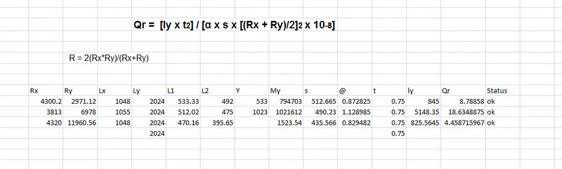
Qr=Iy⋅t2α⋅S⋅[Rx+Ry2]2⋅108Qr=Iy⋅t2α⋅S⋅[Rx+Ry2]2⋅108
whereas,
Iy=Iy= Geometrical moment of inertia of Bow (along Y cross-section)(mm2mm2)
t = thickness of the roof plate sheet
α=My⋅L2x⋅10−12α=My⋅Lx2⋅10-12
My=Y⋅(Ly−Y)My=Y⋅(Ly-Y)
Lx=Lx= Distance between left and right end of the roof measured at the center of the two reinforcement added.
Ly=Ly=Distance from center of front roof rail to center of the rear roof rail.
Y = Distance between the two consecutive reinforcement added
S=L12+L22
S = Distance for which roof bow bears the divided load.
Rx=Rx= Curvature of the roof in X-direction
Ry=Ry= Curvature of the roof in Y_direction