Roof Design
OBJECTIVE :-
- The objective of this project is to design car roof with essential flanges and reinforcements like ditch area , front roof rail , bow roofs, central roof rail and rear roof rail for the the given styling surface
- Perform a curvature study on the roof and perform the calculations for the heat distortion and snow load criteria to determine whether the bow roofs are at the correct positions.
- Finding moment of inertia and section modulus for Bow roofs , central roof rail . front roof rail and rear roof rail .
- Perform the draft analysis for each reinforcements
CAR ROOF:-
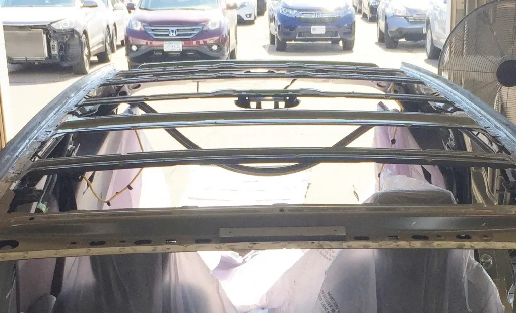
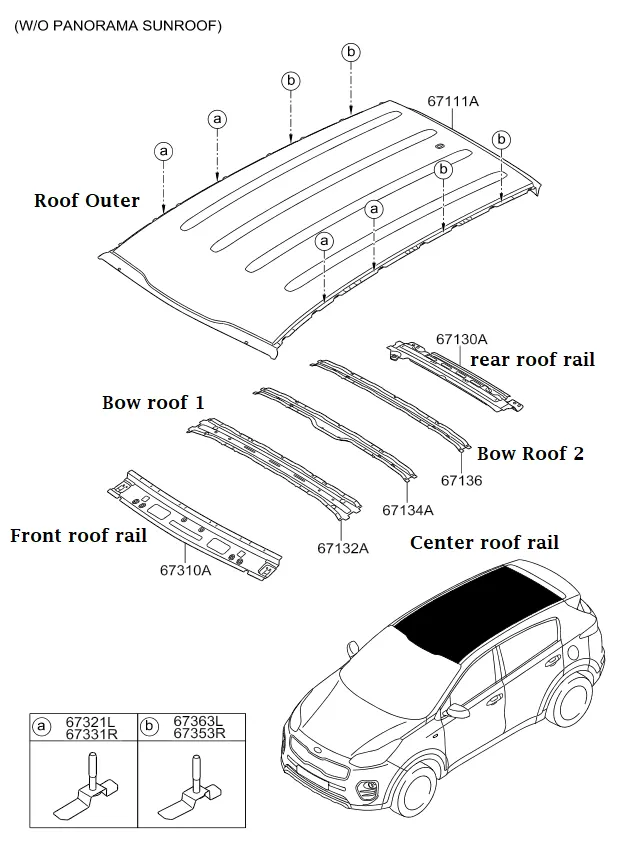
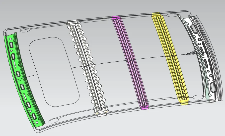
An automobile roof or car top is the portion of an automobile that sits above the passenger compartment, protecting the vehicle occupants from sun, wind, rain, and other external elements. The roof is not a single panel as seen from the exterior it consists of front roof rail, bow roofs, center roof rail, and rear roof rail with different thicknesses which act as a reinforcement for the top.
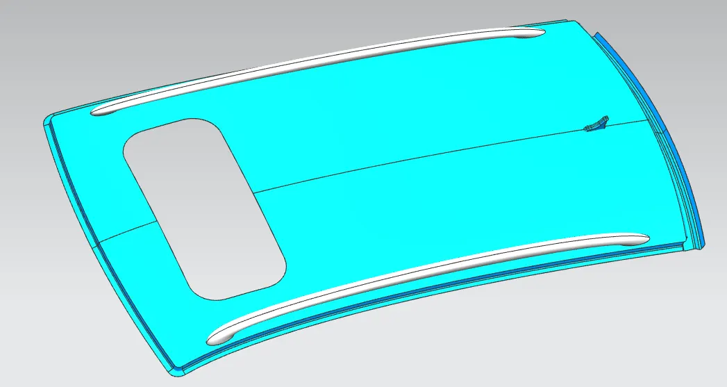
It is the outer surface designed by the styling team for the aesthetics of the vehicle, the BIW team design the way of mounting on the vehicle by considering the necessary reinforcement to support the structure. The reinforcements are designed by considering the necessary load conditions.Designer alos should create the Ditch area in order totaken into account the fixation of the mating BIW Components adjacent to it.First thing to consider while designing the roof is the opening angle, of the flanges such that there is no negative draft.If the roof rail is flat it is weak and if it is tilted or curved then it has more strength.As the roof is large so to increase the strength of the roof where it appears flat due to its long distance Roof Bow are given to increase the strength of the roof.Since the roof has numerous functions so the roof has to be stronger enough to withstand the damage experienced by it. To have good strength and stiffness, the Roof consists of components
The roof assembly must be consists of the support components such as front roof rail and rear roof rail at front and rear ends. These rails connected with the pillar and give the support to the roof.
The center reinforcement is located at the center of the roof structure and is connected to the b-pillar of the BIW structure, which gives the strength to the flat surface of the roof.
Types of car roofs:
- Convertible roofs
- Hardtops
- Sunroofs
- T-tops
- Targa tops
- Vinyl roofs
1) Convertible roofs -
A convertible or cabriolet is a passenger car that can be driven with or without a roof in place. The methods of retracting and storing the roof vary between models. A convertible allows an open-air driving experience, with the ability to provide a roof when required. Potential drawbacks of convertibles are reduced structural rigidity (requiring significant engineering and modification to counteract the effects of removing a car's roof) and cargo space.

2) Hardtops -
A hardtop is a rigid form of automobile roof, which for modern cars is typically constructed from metal.

3) Sunroofs -
A sunroof is a movable panel that opens to uncover a window in an automobile roof, allowing light and/or fresh air to enter the passenger compartment. Sunroofs can be manually operated or motor driven, and are available in many shapes, sizes and styles. While the term sunroof is now used generically to describe any glass panel in the roof, the term "moonroof" was historically used to describe stationary glass panes rigidly mounted in the roof panel over the passenger compartment. A moonroof has a glass panel that is transparent and usually tinted. Previous terms include Sunshine Roof, Sliding Head and Sliding Roof.

4) T-Tops -
A T-top is an automobile roof with a removable panel on each side of a rigid bar running from the center of one structural bar between pillars to the center of the next structural bar. The panels of a traditional T-top are usually made of auto grade safety glass.
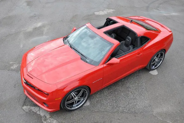
5)Targa Tops -
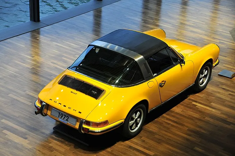
Targa top, or targa for short, is a semi-convertible car body style with a removable roof section and a full width roll bar behind the seats. The rear window is normally fixed, but on some targa models, it is a removable plastic foldable window, making it a convertible-type vehicle. Any piece of normally fixed metal or trim which rises up from one side, over the roof and down the other side is sometimes called a targa band, targa bar, or a wrapover band.
Targa tops are different from T-tops, which have a solid, non-removable bar running between the top of the windscreen and the rear roll-bar, and generally have two separate roof panels above the seats that fit between the window and central t-bar.
6) Vinyl Roofs -
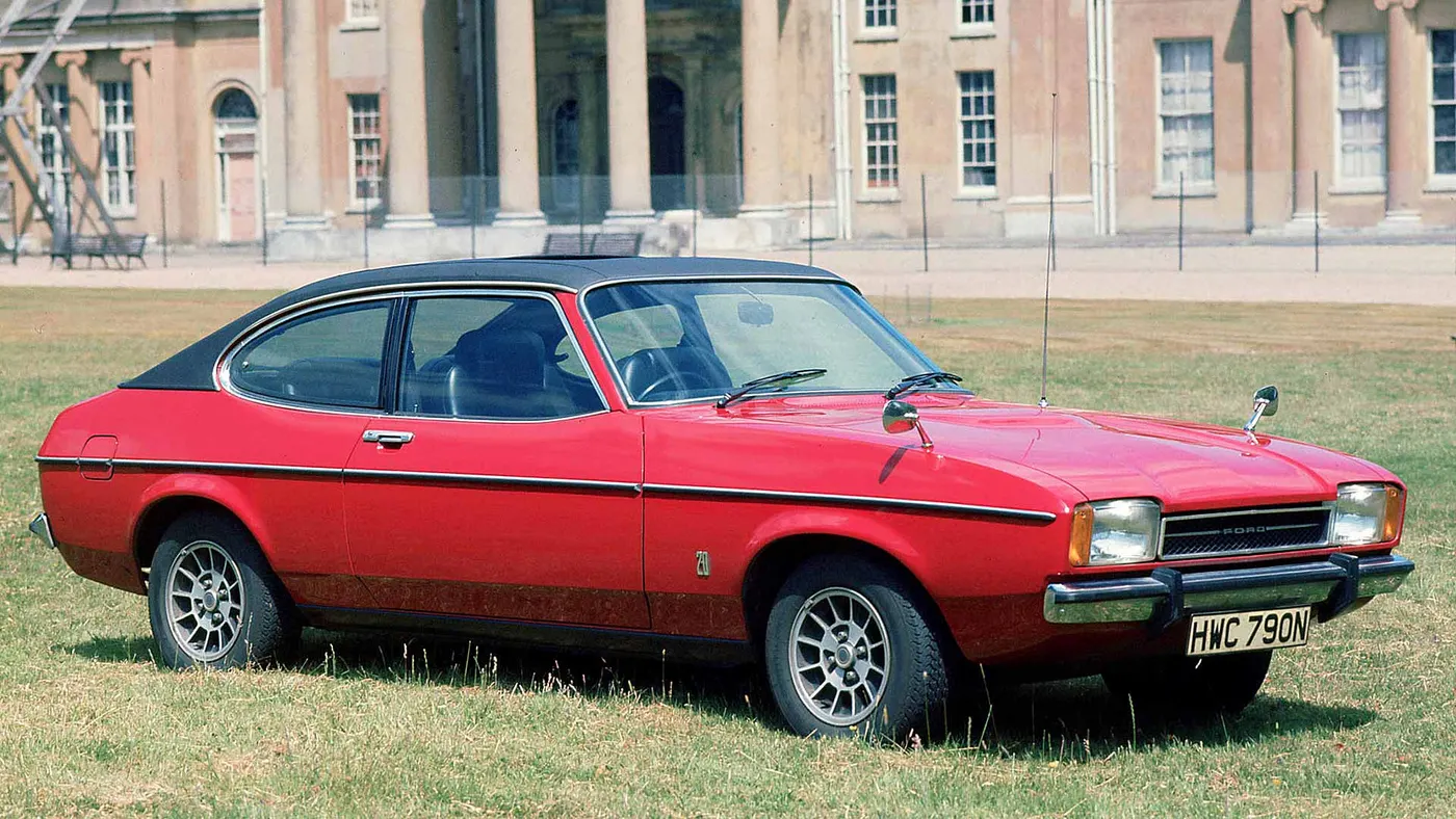
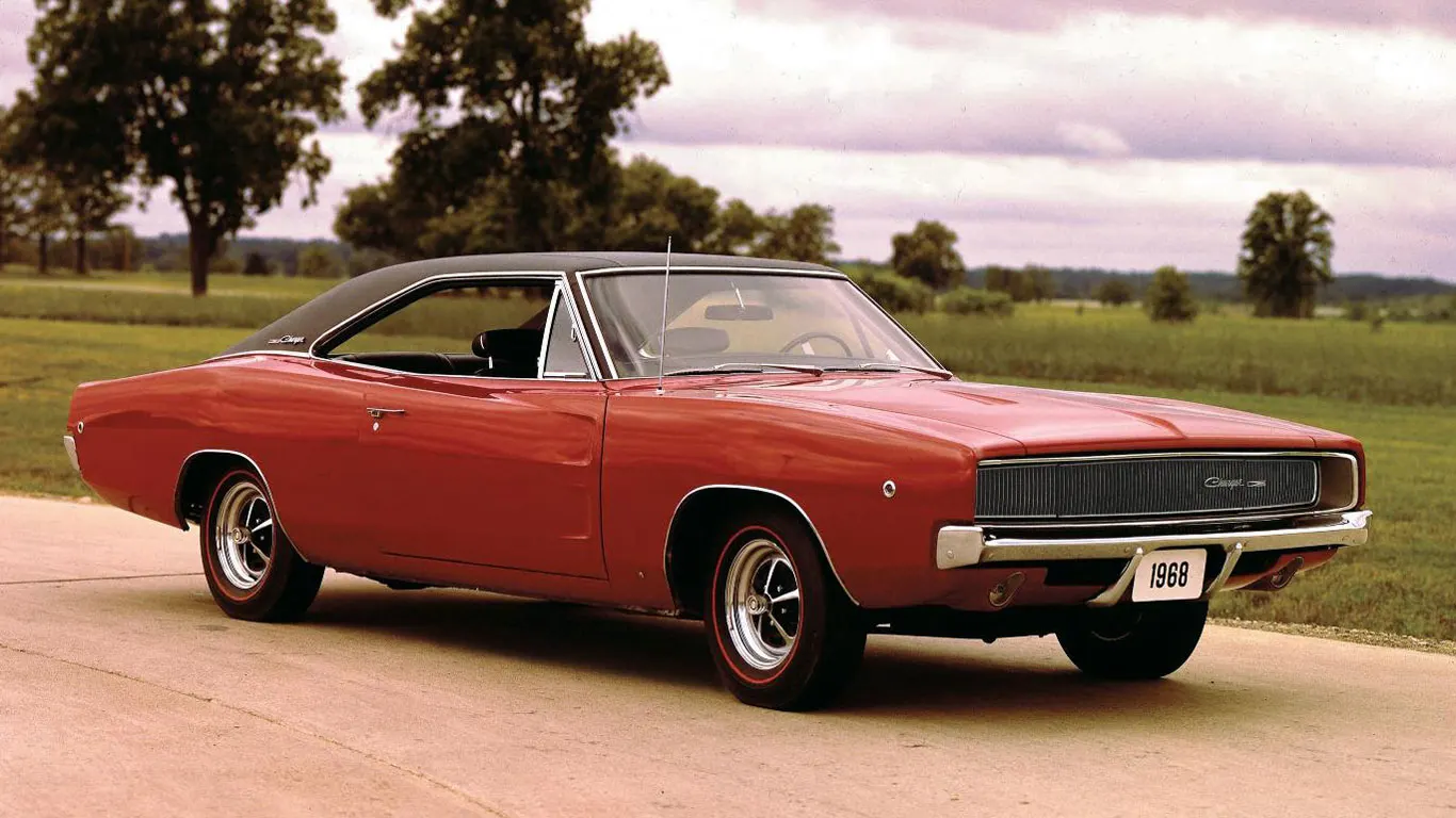
This covering was originally designed to give the appearance of a convertible to models with a fixed roof, but eventually it evolved into a styling statement in its own right. When leather, canvas and vinyl were sometimes used along with landau bars, to give a fairly accurate reproduction of a horse-drawn carriage's movable top.
7) Solar Panel Roof-
The Solar panel roofs are newly developed for electric cars, to charge the batteries by using sunlight without stopping at charging stations which consumes a good time to recharge the batteries. So that the solar panel roofs were developed for on going recharging of batteries.

The basic criteria to design the roof they are
- Visibility criteria
- Head room clearance
- Bow roof position
- Heat distortion and Snow load criteria
- Draft analysis
- Ditch area
- Front roof rail
- Rear roof rail
- Bow roof(No of bow roof depend upon roof length and strenth)
- Reinforcement
- The design requirements for the roof and its components.
- Functional requirements.
- Roll over test regulations & requirements.
- Bow Roof position justification.
- Joining techniques like welding and mastics.
Roof Crush Test for Passenger Car:
Safety point of view vehicle roof plays a very crucial role especially roll over kind of accidents, in which vehicle tips over onto its side of the roof. And vehicle rollover crashes are the cause of many fatalities and head, neck, and spine trauma around the world.
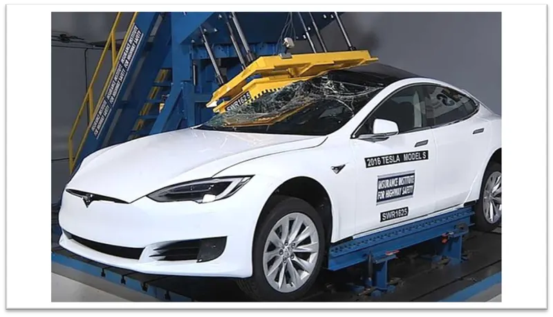
Therefore, passenger safety is also a very important parameter in front of OEMs. It is not only a marketing strategy but also it is an obligation stipulated by international standards that are now placed in several countries, as well as a governmental requirement. For this reason, strength is a very important criterion for designing a vehicle roof.
The strength of the roof structure to occupant protection in real-world rollover crashes, requiring the maximum moving distance of the roof structure should be less than 127 mm (5 in.) when the induced load is 1.5 times the vehicle weight.
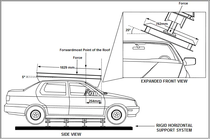
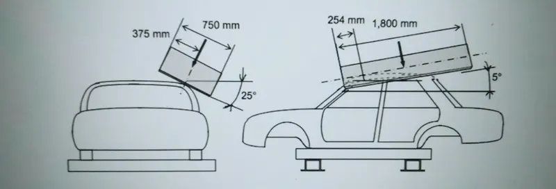
For the test, the passenger car shall be rigidly placed or positioned on a horizontal surface with the doors locked and the window closed. Furthermore, a flat, rigid block with a lower surface a rectangle measuring 30 inches wide by 72 inches long (762mm X 1829mm) shall not move more than 5 inches(127mm), measured as the distance between the original location of the lower surface of the test device and its location as the specified force level is reached, when it is used to apply a force of 1.5 times the unloaded vehicle weight (UVW) or 5000 lbs(22224N), whichever is less, to either side or forward edge of the vehicle.
This test can be conducted on either side of the roof structure, the front left or the front right side but not on both sides in one single test and still meet the requirements of the test. The rigid plate shall not move faster than 0.5 inches/second and the force applied on the plate shall not exceed the lesser of 1.5 times the unloaded vehicle weight (UVW) expressed in kilograms multiplied by 9.8 or 5000lbs (22240N).
Also, the direction of the force shall be downward and perpendicular to the lower surface of the rigid plate and such that it moves in a straight line without rotation. The duration of the test shall not exceed 120 seconds. The longitudinal axis of the plate is pitched forward at a 5 º angle as viewed from the side of the passenger car as shown in below fig..,
WHY REINFORCEMENTS :
If the roof is flat it is very weak and cannot able to with stand the forces like snow , so in order to increase the strength of the roof these reinforcements like front roof rail, central roof rail, rear roof rail and the bow roofs are introduced and joined to the flat surface of the roof with the different joining process
Different types of reinforcements that the car has are :
- Front roof rail
- Bow roofs
- Central roof rail and
- Rear roof rail
INFORMATION REGARDING ROOF RAILS
Mastics are applied between roof and the roof rail and bow roof. When the mastic gooses out it joins the roof rail, bow roof with the Roof.
As we have curvature in front and more flat in the back side of the roof, it is sufficient to have reinforcement centre alone in front and both the roof bows behind.
If the roof was small with better curvature we use only one centre reinforcement roof rail which also acts as the roof bow.
Number of bow roof increases if the car size becomes longer and taller. More taller car means more flat region means more Bow roofs.
If the styling surface does not with stand the Heat Distortion criteria and snow load condition or the strength of the roof is less then in styling surface modify the radius of curvature of the roof and send it to the styling team if they accept it then proceed.
So as to propose a value of that curvature radius will have to do trial error for the values of Rx and Ry.
Always gradually increase the curvature radius not drastically.
If the styling team does not accept the change in radius of curvature of the surface then embossing is done on the roof of different shapes so as to increase the strength of the roof.
Always place Roof Bows on the flat region and not on the curvature region.
Also there is a bracket placed on the reinforcement centre so as to mount the room lamp in the car.
1) FRONT ROOF RAIL:
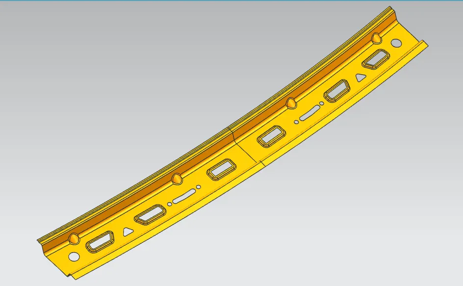
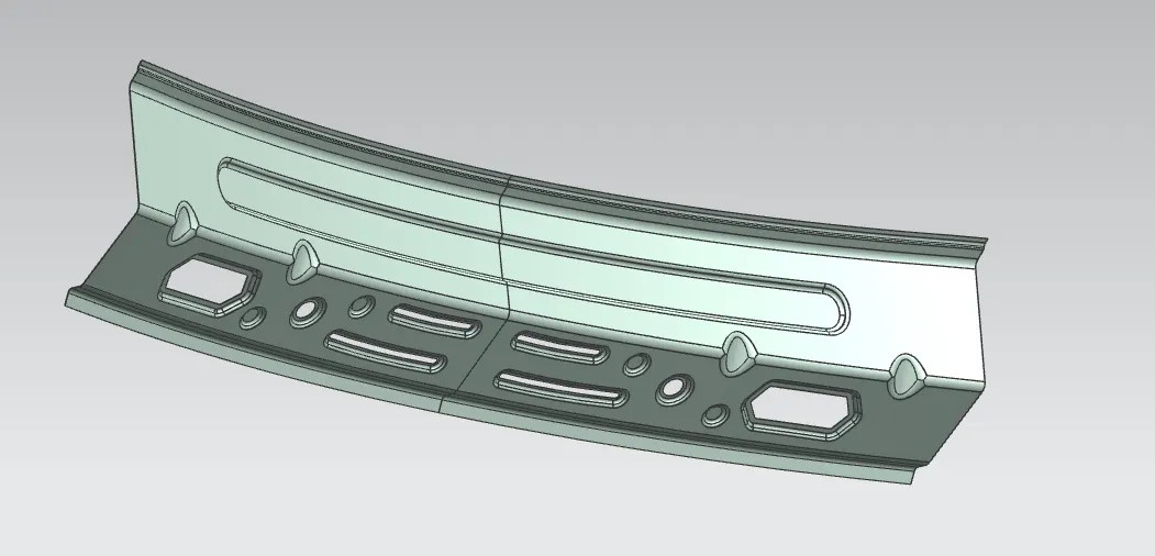
Front roof rail is the additional commodity attached to the roof which gives the reinforcement and also having the certain features in it which helps in attaching the Bracket map lamp and the room lamp which will be mounted on this rail.
Front roof rail is used for supporting the roof for externally applied forces occurring at accidents. When we increasing the front roof rail is good for strength but also it is not for drivers because of it hide visibility of road.When considering the parameters of roof rail, give them 60-80mm length, proper draft angle and also using the embosses for increasing the strength. Front section of front roof rails spot welded to the front ditch area and other end is fixed with help of mastic sealants.
Sheetmetal thickness t = 0.75mm
Flange length = 13.2 > 3t+R
Radius = (3mm or 5mm) > t
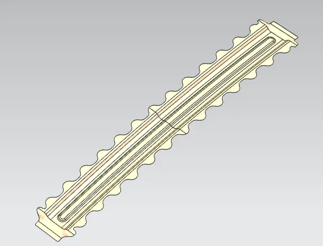
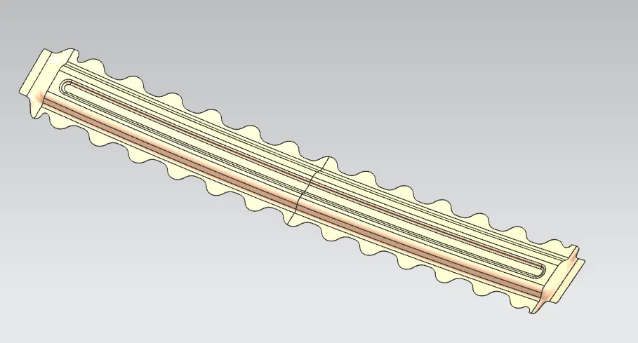
2) BOW ROOF -01:
The bow roofs are given to the improve the torsional stiffness and load bearing capacity of the roof structure. When number of bow roofs are given by the roof dimension. Longer the roof area we have to give the more bow roof to the structure.Positioning of the bow roofs are decided by the curvature study. The Heat distortion and Snow load criteria are checked to analyze the bow roof position by various condition.We also give the Mastic area for fixing the Bow roof to the roof outer. Each mastic sealants are having 80mm circular effective area of surroundings. Thickness of the Bow roof is 0.75mm.
3) BOW ROOF -02:
It is also same to the Front bow roof but the positioning bow roof only change. The bow roofs are given to the improve the torsional stiffness and load bearing capacity of the roof structure. When number of bow roofs are given by the roof dimension. Longer the roof area we have to give the more bow roof to the structure.
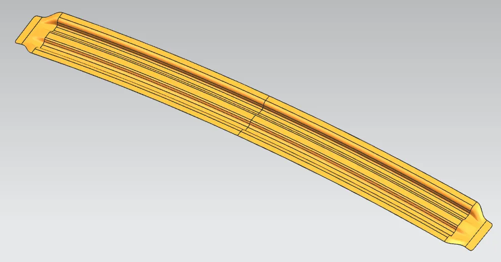
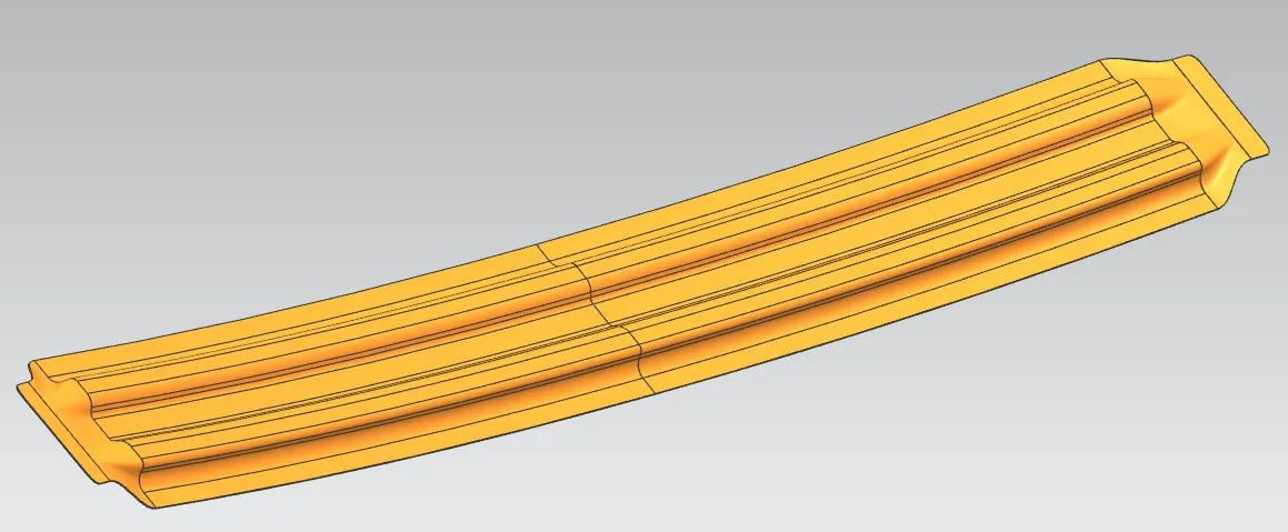
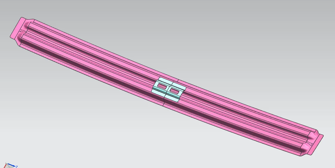
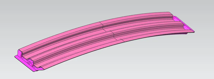
4) CENTER BOW ROOF RAIL:
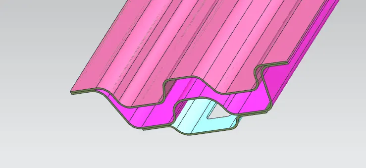
it is the one of the main roof to support the outer panal and the front and rear panal are uses to support the outer panal but center support is the main supporting system to hold the roof in the same position to thicken the center bow roof to thickess of 0.75mm.
Central roof rail helps in providing effectively support to the flat area of the roof as it is more susceptible to failure under the action of load. Generally central roof rail is placed at the center of the roof which is connected to the B-pillar support structure. This central roof rail helps in the strength to the roof during the roll-over test.
5) REAR ROOF RAIL:
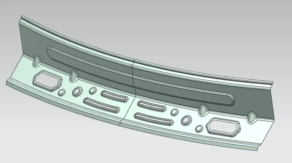
Rear roof rail is creating to length 80-100mm with proper draft angle. Give embosses on the sheet to ensure the enough strength for holding the roof structure. When considering the all parameters like length, width, sealants, rubber materials, wind shield to create the design properly.
Head room clearance = 120mm
Sheetmetal thickness = 0.75mm
Radius = (3mm or 5mm)
Roof Mastic Information:
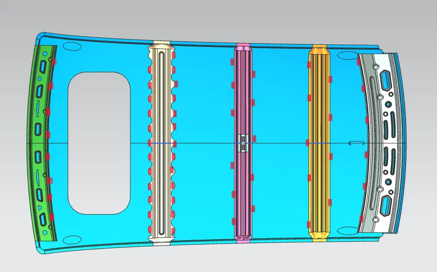
It is basically an NVH topic mastics are point / surfaces given on embosses for applying mastic sealant to join outer and inner panel and also give good value of NVH.
So mastic sealants are joining material used to join inner and Outer panel and at the same time reduces the NVH value.
One spot of mastic sealant provides strength locally at around 80 mm so we need to put these mastic points in such a way that it covers the most of the hood region except reinforcement area of latch and hinge because that alone provide good NVH so no worries there.
Here I have spotted points where I have applied mastic data when mastic sealant will be applied and while undergoing hot bath it gets hardened & make the joint strong.
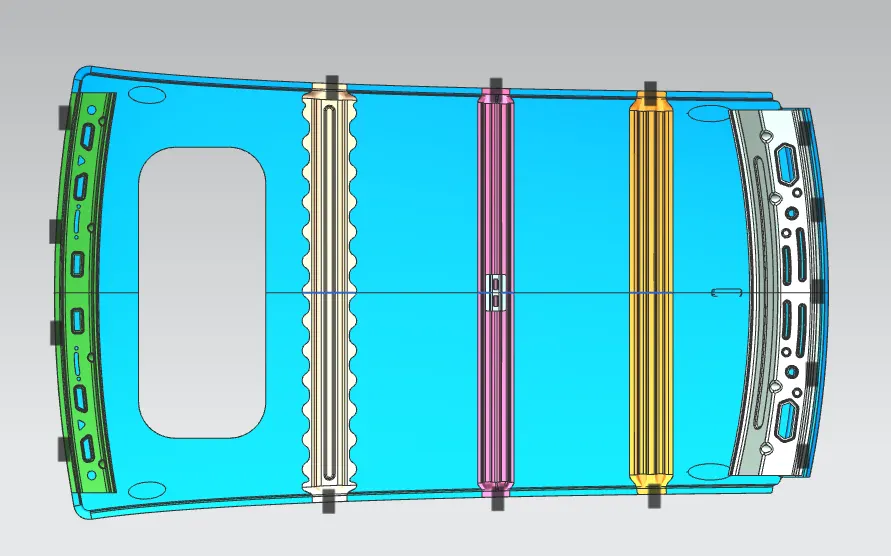
Spot Weld Information:
Draft Analysis:
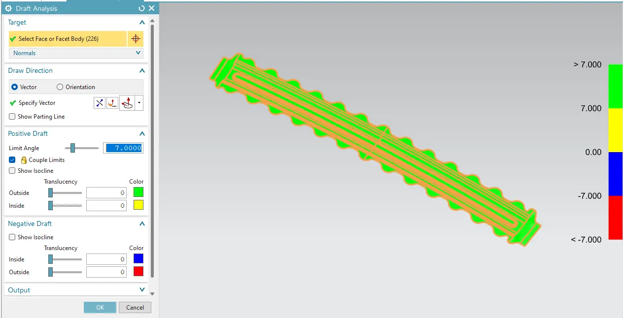
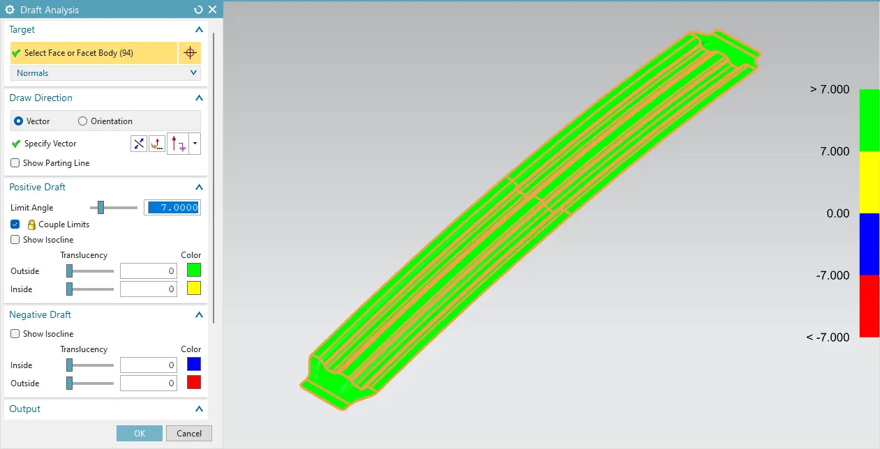
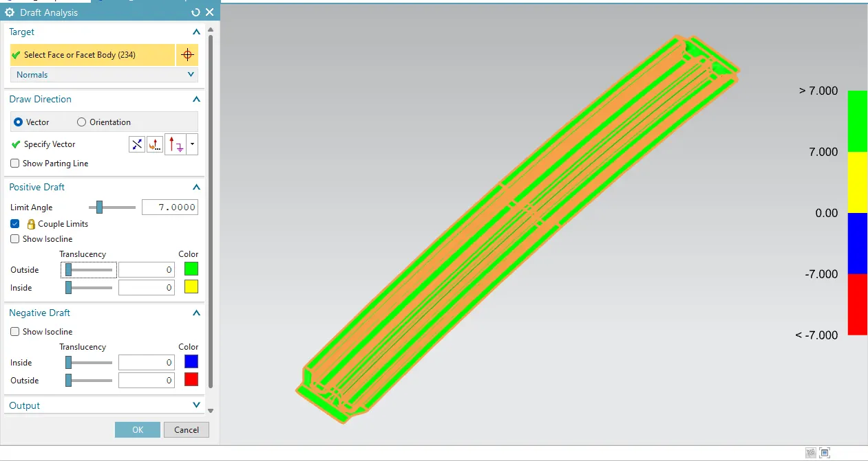
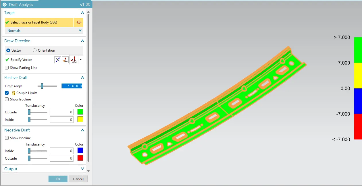
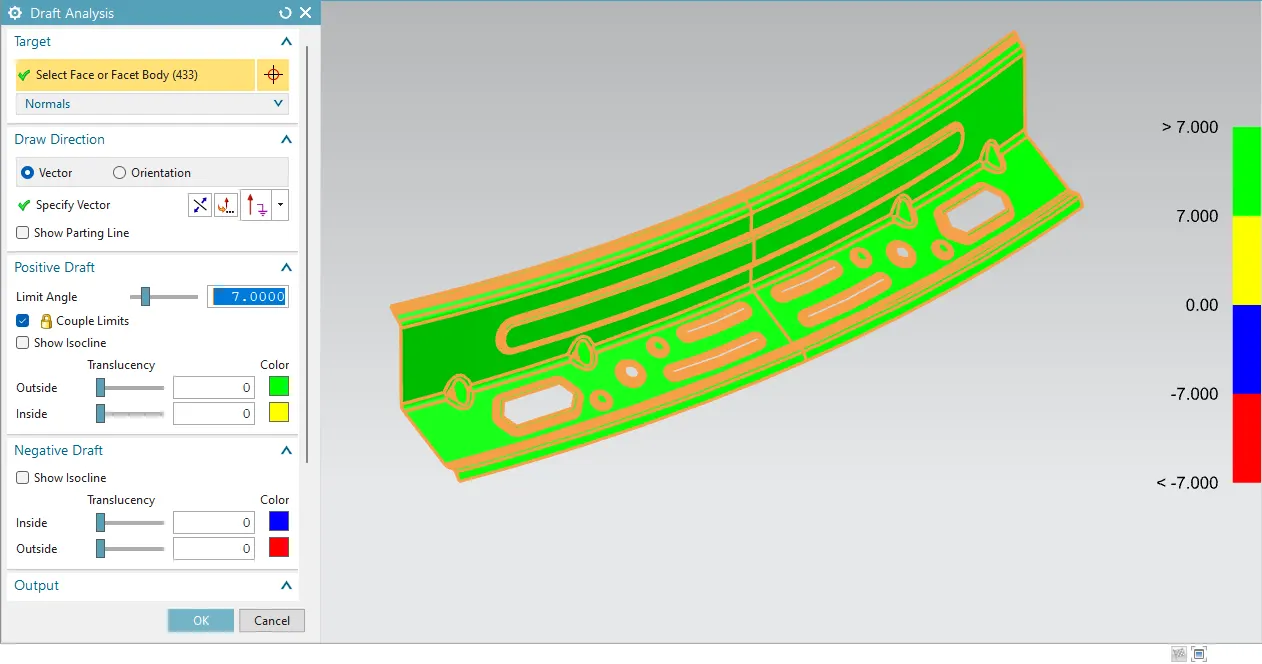
Parts Cannot be ejected from the tool if it is at 90 degree surface.for the reason,A small Draft angle is to be provide for each and every surfacs of the Component in order to easy removal of component from the moulds without any defects.Draft is the angle in which the part is tapered to allow it to release.Most of the sheet metal part require minimum 7degree 10 degree however 7 degrees are widely accepeted in sheet metal component design.Draft Analysis is the technique used to analise weather our designed product are manufacturable with required conditions or not.Below shown image is the Draft analysis of the above designed Roof:
BOW ROOF-01
BOW ROOF-02
CENTER REINFORCEMENT
FRONT ROOF RAIL
REAR ROOF RAIL
HEAT DISTORTION:
The heat distortion study the plays an important role in Sheetmetal application. Heat distortion is temperature limit above which material cannot be used for structural application. This study is useful to fin the where the material starts to soften when exposed to a fixed load at elevated temperature. In order to avoid the bending, damage to the roof based on the heat distortion temperature. This study will provide the which position of the bow roof give enough strengthen to roof.
Predicting Heat Distortion for the roof is important since it is exposed to heat for a long time and high temperatures will affect the roof structure if the design does not
conform with the heat distortion criteria. This study helps to determine the positions of Bow roofs to provide strength to the roof to avoid bending or deformation of the
roof due to heat. Bow roof curvature study using the below formula will help us to check whether the Bow roof positions impart required strength to the roof.
Steps to calculate the Heat distortions as follows:
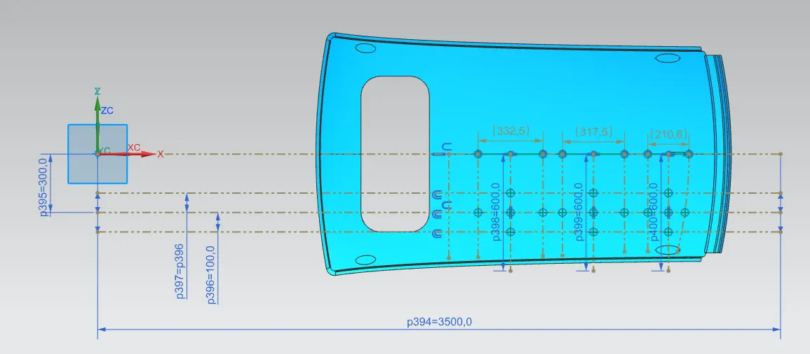
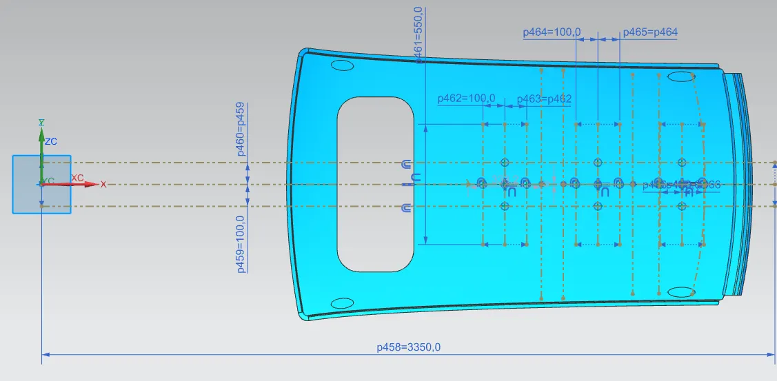
1.First we offset the center y-axis line to 300mm distance apart from it represented as (-3Y to 3Y red line).
2.After that we offset this -3Y to 3Y to 100mm offset each side represented with the green line.
3.We draw the vertical red line at the center of the two consecutive bow rood span. Next, we offset this red line to 100 on each side.
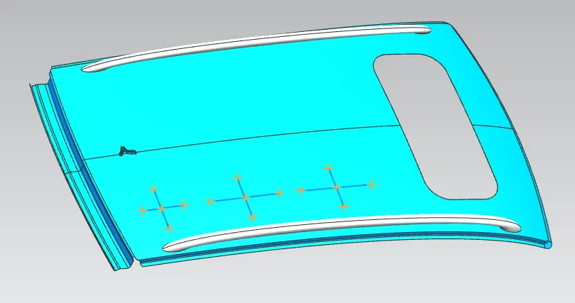
4. Now we have three horizontal lines and three 12 vertical lines we take the intersection points of the vertical red line with three horizontal lines and a horizontal red line we take the intersection of the vertical lines with that line.
5.After getting all the points we project these points on the roof surface and draw the three points curve along the x-axis point to get the radius of curvature of Ry and along y-axis points to get the radius of curvature of Rx.
Bow–Roof Prediction Formula:
W = [1.73 x 10^(-3) x L] + [1.85 x 10^(-8) x (R^2)/t] + [ 1.10x10^(-3) x l] - 2.68
Where,
L = Roof Length in X-Direction[mm](Roof dimension in 0-Y)
R = Roof curvature
R = 2(Rx*Ry)/(Rx+Ry)
Rx = X curvature
Ry = Y curvature
t = Roof plate thickness [mm]
l = Bow Roof Span [mm]
All the support in the inner panal bows are all in 0.75mm thickness (t)
Roof length L:
the total length of the outer panal is 2033.7 mm
BOW ROOF SPAN (I):
Here we want to take the distance from front roof rail to bow roof front for finding the bow roof span(I), we want to measure another bow roof span
Rx & Ry:
From 0-Y axis, at -3Y about distance 300mm is drawn parallel on the perpendicular plane. After that 100mm lines are offset to either side of -3Y line. Now center lines are drawn between each adjacent roof rail edges respectively. Intersection points are marked on the sketch. Make all geometry lines are construction lines except points.Project the intersection points on sketch to the Roof surface.Join the intersection points in roof surface using the arc curve an measure the radius using the minimum radius comment.
Heat distortion of final calculation:

When We have the necessary values for finding the heat distortion value(W):
W = [1.73 x 10^(-3) x L] + [1.85 x 10^(-8) x (R^2)/2] + [1.10 x 10^(-3) x I] - 2.68
Apply the all the values,From the above table we, conclude that all the values are of W< 2>. So, that all bow roofs areas are placed at the right place.
SNOW LOAD PREDICTION:
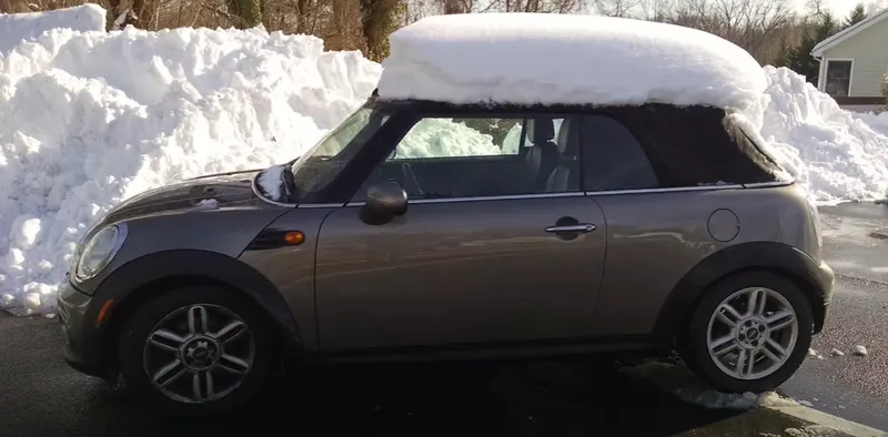
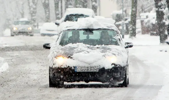
Why to do this snow load prediction because in india it is an tropical climate so the snow will not happen in winter climate but in foreign countries they have an snow fall in all the year during winter time so the snow load prediction it is used to check the if the the snow is happen in the top of the roof it will put the too much of load on the outer panal so that reason only to apply this prediction to pass this test car will be applicable for snow countries. to identify this by using this formula they are,
This test is done to know the withstand capability of the roof in assembled conditions while snowfall. When the snow was there for a long time the roof goes slightly down and after removal of that load, whether it's coming back to its original shape without having any permanent deformation or not.
Steps to calculate snow load condition:
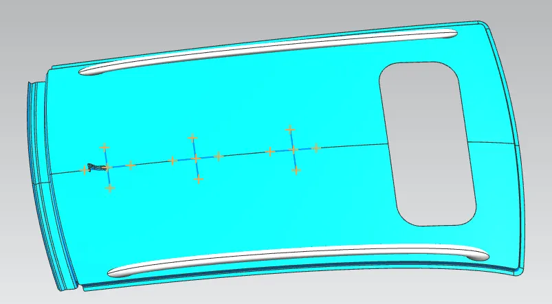
1.Steps is same as heat distortion criteria but the difference is we calculate the Rx and Ry at the centerline of the roof along the y-axis
2.We have to calculate the moment of inertia of each reinforcement(Bow) which can as follows in NX software.
a.We use the intersection curve command in NX software to get the sectional area of the bow along the XY plane.
b.Now we project these curves on the other plane parallel to XY-plane at some offset distance.
c.Now we use a sectional inertia analysis tool to calculate the MOI as follows;
1.For BOW1
Qr = [Iy x t2] / [α x s x [(Rx + Ry)/2]2 x 10-8]
Where
α = My x Lx2 x 10-12 , My = Y(Ly-Y)
Judgement condition = Qr ≥ 3.1
250 ≤ s ≤ 380
t = Roof plate thickness [mm]
Ly = Distance between the front and rear roof Rails on the Vehicle along with 0Y[mm]
Length of Roof panel with the center point between Roof rail Front /Rear as the front and rear reference point.
Lx = Distance between the Left and Right end of the roof on the Roof BOW [mm]
The width of the roof panel is exposed on the surface.
Y = Distance front Front Roof Rail to Roof BOW[mm]
s = Distance for which Roof BOW bears divided load [mm]
s = L1/2 + L2/2
Iy = Geometrical moment of inertia of Roof BOW (Y cross-section )[mm4]
Rx = Lateral direction curvature radius of roof panel Y cross-section on Roof BOW [mm]
Roof panel curvature Radius of the Length Lx in Front view
Ry = Longitudinal Direction curvature radius of the Roof panel X cross-section on Roof BOW [mm]
Roof panel X curvature radius of length s in Side view

SECTION ANALYSIS:
Section moment of inertia is used to predict the amount of deformation and deflection of a part. A higher moment of inertia is preferable as it reduces the amount of deflection for a given force. The thickness of the part and addition of flanges and embosses increase the section inertia of the part. Here the master sections of the roof and roof rails and their section analysis.
There are two types of section modulus we have,
- Elastic section modulus
- Plastic section modulus
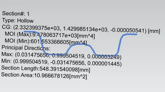
CENTER REINFORCEMENT:
I = MOMENT OF INERTIA
Y = distance between the neutral axis to extreme end of the object.
S = section modulus
Imax = 9.47806x10^3 mm^4
Imin =601.55 mm^4
Section modulus = moment of inertia / distance between the neutral axis to extreme end of the object.
S= I/Y
S= Imax/y=9.47806x10^3/50
S max= 189.74mm^3
S= Imin/y= 601.55/50
S min= 12.031mm^3
BOW ROOF-01:
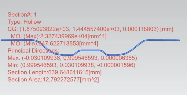
Imax =2.3274X10^4 mm^4
Imin = 347.6227 mm^4
S max= 310.32 mm^3
S min= 4.63 mm^3
BOW ROOF-02:
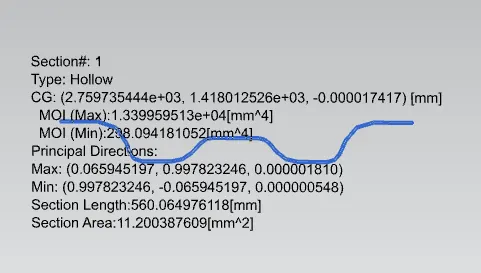
Imax =1.3399X10^4 mm^4
Imin = 298.094 mm^4
S max= 223.3166 mm^3
S min=4.96 mm^3
FRONT ROOF RAIL:
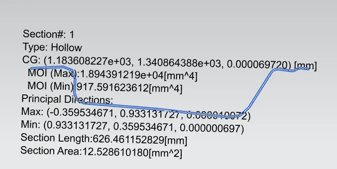
Imax =1.89439X10^4 mm^4
Imin = 917.5916 mm^4
S max= 290.31 mm^3
S min= 14.06mm^3
REAR ROOF RAIL:
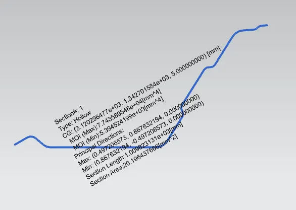
Imax =7.7435X10^4 mm^4
Imin = 5.3945X10^3 mm^4
S max= 720.32 mm^3
S min= 50.181 mm^3
Conclusion:
Thus the Roof is designed and its is provided with the Front and rear rails,Bow roof and Reinforcement for the strength of the roof and also calculated the heat distortion and Snowload criterias.Bothe the Heat distortion and the snow load criteria are satisfying the Condition.
Draft Analysis has been carried out provided 7 degree in order to check the maufacture feasibilty of the components.