Roof Design
ROOF:
An automotive roof or car top is the portion of the automobile that sits above the passenger compartment, protecting the vehicle occupants from Sun, Wind, Rain and other external element.
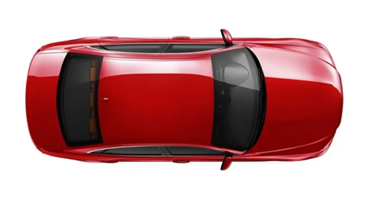
I designed roof project as shown in the below image:
1)provided emboss for higher strength
2)sunroof space is also provided
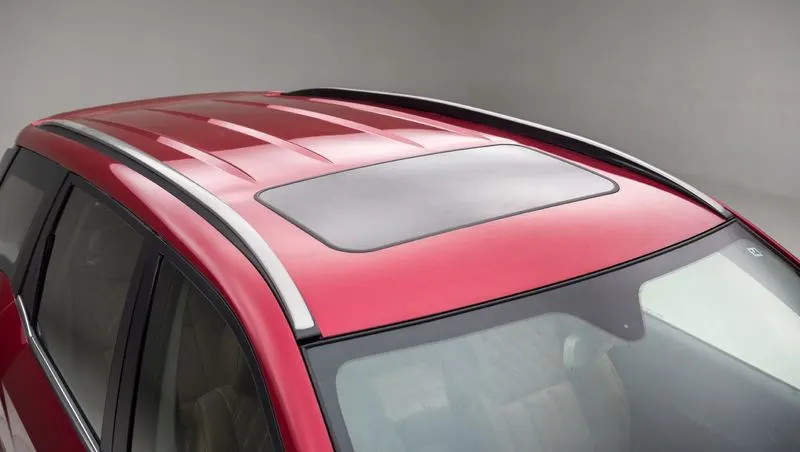
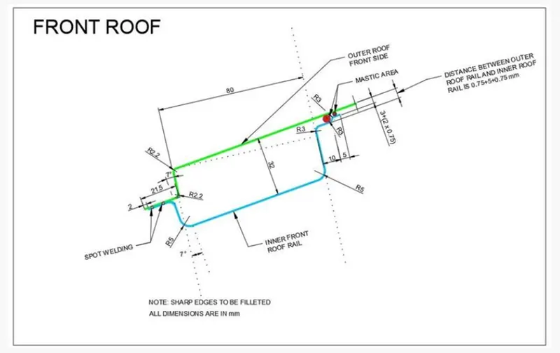
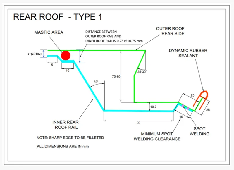
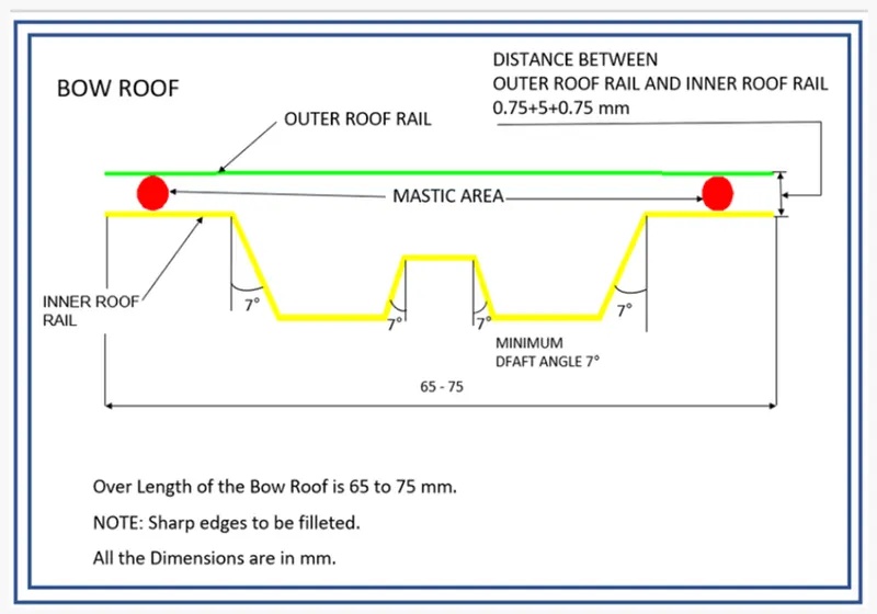
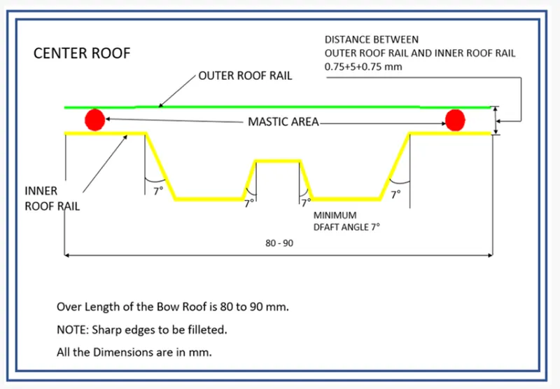
Under the styling surfaces that’s is seen from the outside, there are many other structures under the roof that contributes to its strength and stability. The number of such reinforcement structures/supports differ with respect to the size of the vehicle. They are primarily installed on the flatter areas of the roof to enhance the strength.They are the Front Roof Rail, Rear Roof Rail, Center Rail and Bow Roof Design which are given Mastics and spot welded to the roof flanges & ditch are and improve NVH value by increasing the strength of the roof of using mastics sealants.
ROOF DESIGN CONSIDERATION:
Visibility Criteria
Head Clearance
Curvature Study
Heat Distortion and snow load criteria
Draft Analysis
Safety Parameters
ROOF CRUSH TEST:
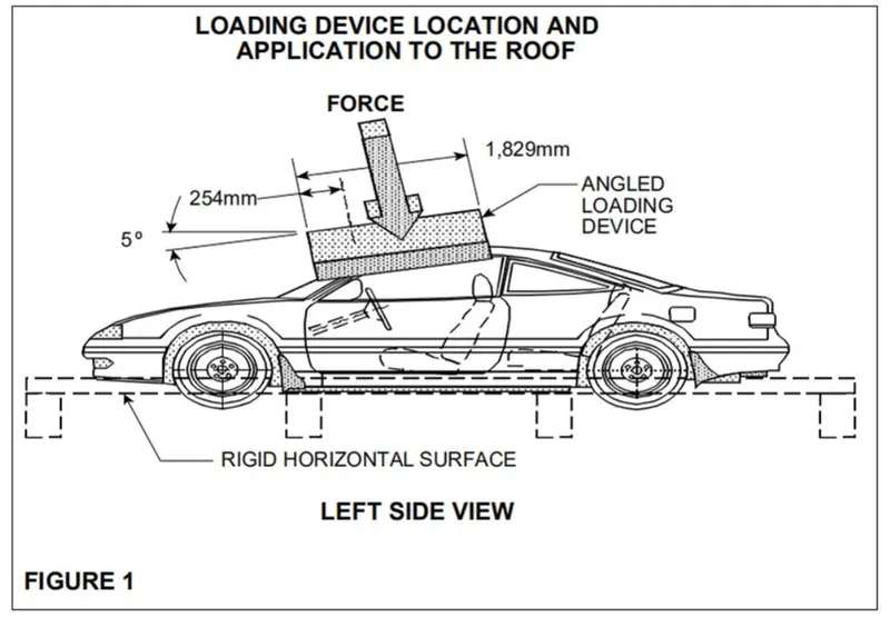
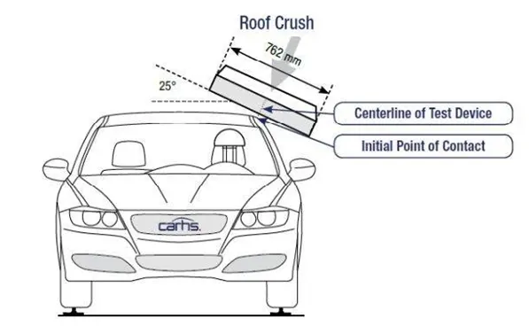
Safety point of view vehicle roof plays a very crucial role especially roll over kind of accidents, In which vehicle tips over onto its side of the roof Vehicle rollover crashes are the cause of many fatalities and head, neck and spine trauma around the world.Strength of the roof structure to occupant protection in real world roll over crashes, requiring the maximum moving distance of the roof structures should be less than 127 mm, (5 in), where the induced load is 1.5 times the vehicle weight.For the test, the passenger shall be rigidly placed or positioned on a horizontal surface with the doors locked and the window closed. Furthermore, a flat, rigid block with a lower surface a rectangle measuring 30 inches wide by 72 inches long (762mm x 1829 mm) shall not move more than 5 inches (127mm), measured as the distances between the original location of the lower surface of the test device and its location as the specified force level is reached, when it is used to apply a forces of 1.5 times the unload vehicle weight (UVW) or 5000 lbs. (22224N), whichever is less. To either side or forward edge of the vehicle.The rigid plate shall not move faster than 0.5 inches/second and the force applied on the plate shall not exceed the lesser of 1.5 times the unloaded vehicle weight (UVW) expressed in kilograms multiplied by 9.8 or 5000 lbs (22240N).Also, the direction of the force shall be downward and perpendicular to the lower surface of the rigid plate and such that it moves in a straight line without rotation. The duration of the test shall not exceed 120 seconds. The longitudinal axis of the plate is pitched forward at a 5’ angle as viewed from the side of the passenger car.The lateral axis or the roll of the plate is such that it forms a 25’ outboard angle with a horizontal surface as viewed from the front of the passenger car.
REINFORCEMENT(SUPPORT FEATURE):
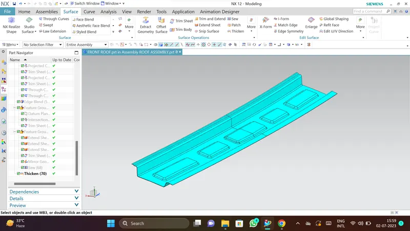
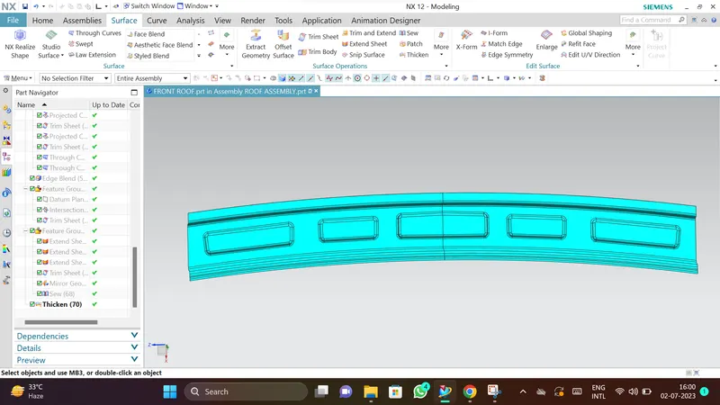
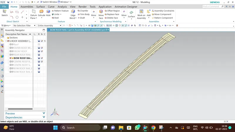
If the roof is flat, it is weak and cannot able to with stand the external load like snow load, roll over and etc. so in order to increase the strength of the roof, reinforcement like front roof rail, central roof rail, rear roof rail and the bow roof are introduced and joined in the flat surface of the roof with different joining process.Mastics are introduced between the roof outer panel and the reinforcements for joining. Where ever the mastics are introduced there is remarkable strength. Spot welding is also introduced to join the reinforcement and the outer panel.
MATERIALS:
5 Types of Metal Roofing
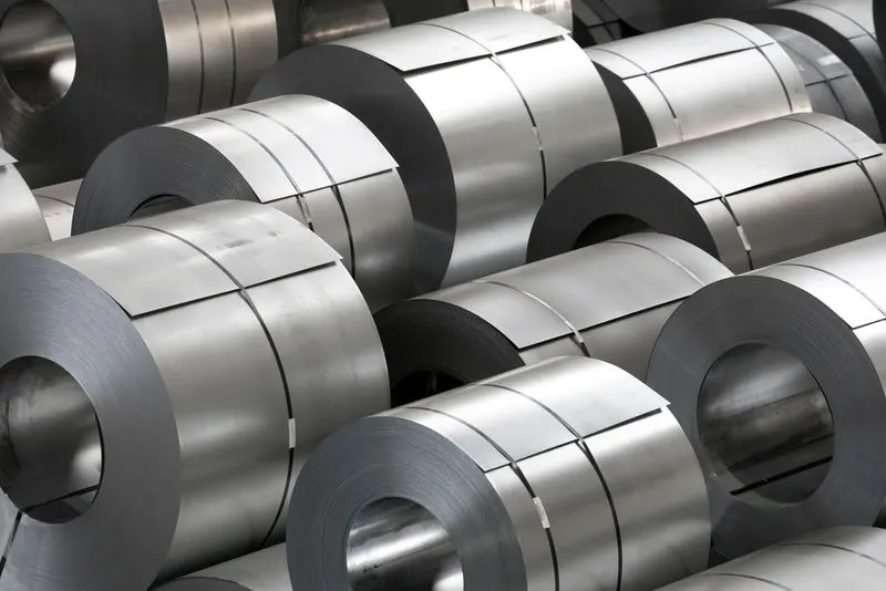
- Copper - Extremely long-lasting, very soft with low melting temperature
- Aluminum - Long-lasting, resistant to salt water corrosion
- Zinc - Extremely long-lasting, resistant to corrosion and lowest melting point
- Steel - Three variations: galvanized, galvalume, and weathering steel (corten)
- Tin - Often referring to steel, used prior to World War II. No longer commonly applied.
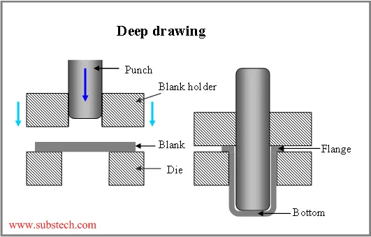
Deep drawing:
Deep drawing is a sheet metal forming process in which a sheet metal blank is radially drawn into a forming die by the mechanical action of a punch. It is thus a shape transformation process with material retention. The process is considered "deep" drawing when the depth of the drawn part exceeds its diameter. This is achieved by redrawing the part through a series of dies. The flange region (sheet metal in the die shoulder area) experiences a radial drawing stress and a tangential compressive stress due to the material retention property. These compressive stresses (hoop stresses) result in flange wrinkles (wrinkles of the first order). Wrinkles can be prevented by using a blank holder, the function of which is to facilitate controlled material flow into the die radius. The feasibility of this deep drawing is called Drawability
TYPES OF ROOF:
Front roof rail
Central Roof rail
Rear roof rail
Bow roof rail
MASTERSECTION AND DESIGN:
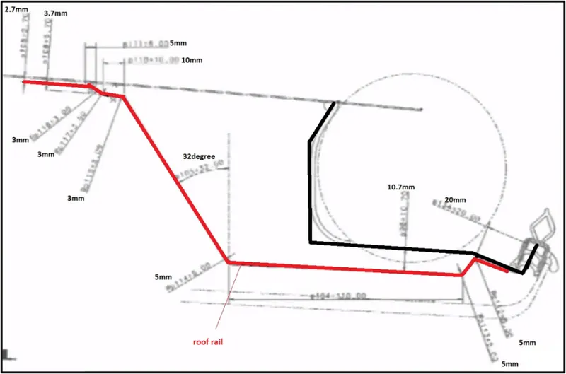
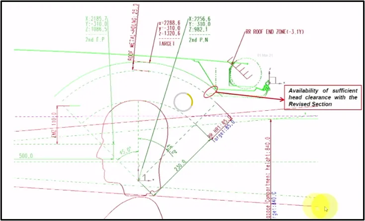
Head room clearance and field rear Vision:
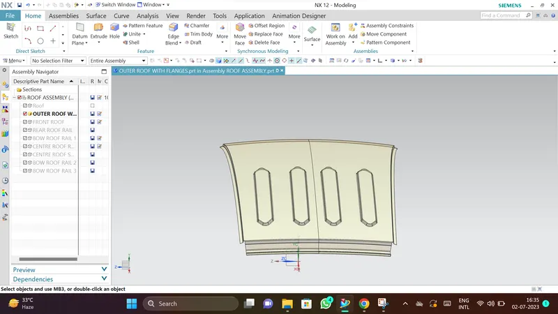
OUTER ROOF WITH FLANGES:
top view :
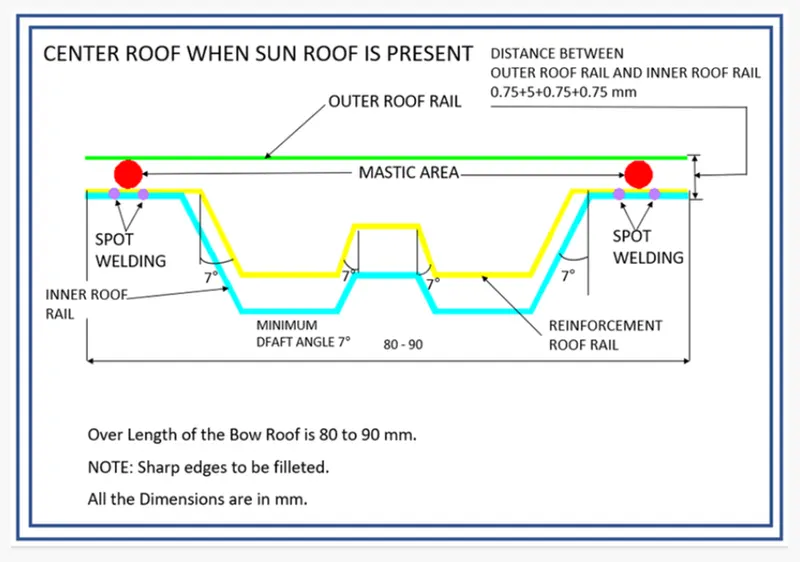
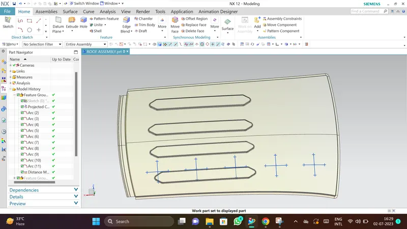
Here i have created the embosses on the top surface of the roof.It will increase the strength of the roof.
In this roof design we can fix sunroof .so necessary gap is given at the front portion of the roof
FRONT FLANGE:
REAR FLANGE:
SIDE FLANGE:
FRONT ROOF RAIL:
BOW ROOF 1:
SUPPORT RAIL:
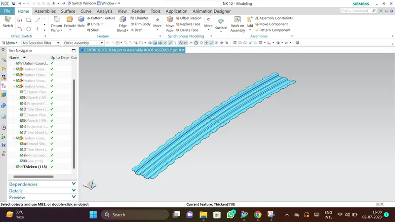
CENTRE RAIL:
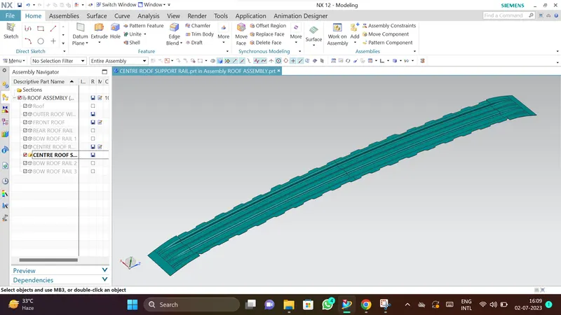
CENTRE ROOF RAIL WITH SUPPORT ROOF RAIL :
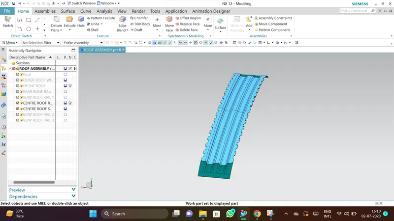
BOW ROOF2:
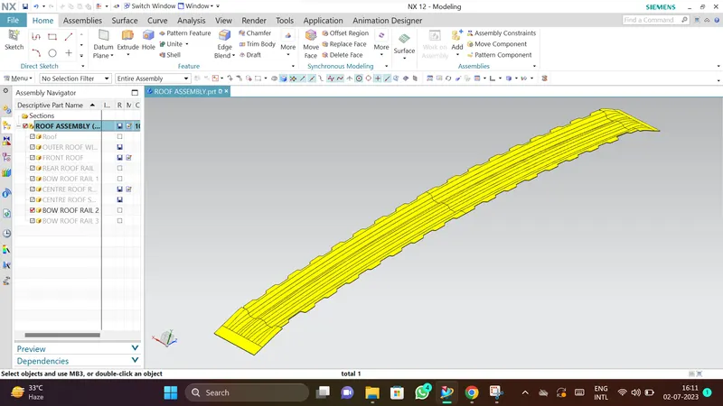
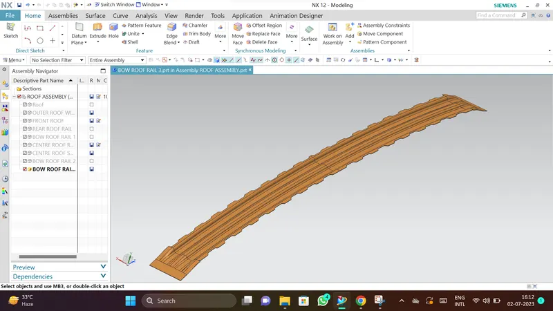
BOW ROOF 3:
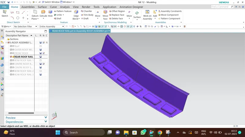
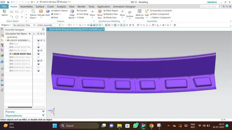
REAR ROOF RAIL:
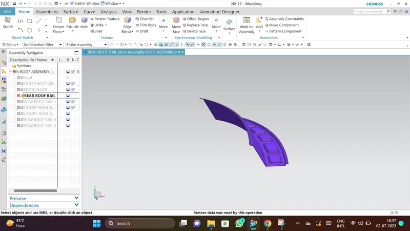
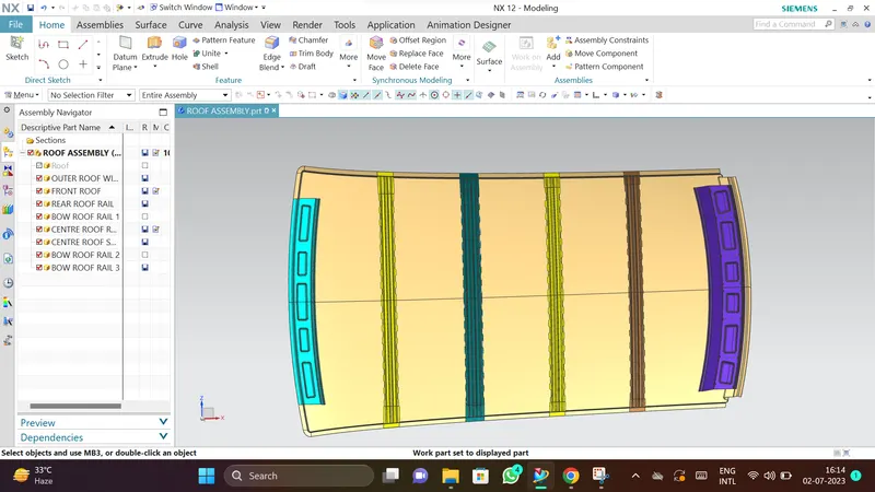
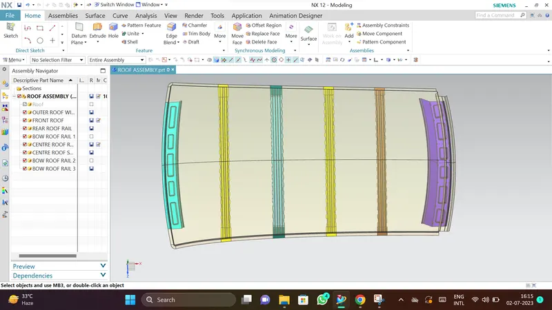
FINAL ROOF ASSEMBLY:
Roof Mastic Information:
It is basically an NVH topic mastics are point / surfaces given on embosses for applying mastic sealant to join outer and inner panel and also give good value of NVH.
So mastic sealants are joining material used to join inner and Outer panel and at the same time reduces the NVH value.
One spot of mastic sealant provides strength locally at around 80 mm so we need to put these mastic points in such a way that it covers the most of the hood region except reinforcement area of latch and hinge because that alone provide good NVH so no worries there.
Here I have spotted points where I have applied mastic data when mastic sealant will be applied and while undergoing hot bath it gets hardened & make the joint strong.
Heated Distortion study on the roof:
The heat distortion study plays a major role in sheet metal usage. Heat distortion temperature is the temperature limit above which the material cannot be used for the structural applications. This study is used to predict the heat distortions temperature at the material where it start to soften when exposed to a fixed load at elevated temperature. In order to avoid bending or damages on the roof, based on the heat distortion temperature, this study will predict the bow roof position which helps to strengthen the roof.
BOW – roof prediction study:
| W= [1.73x10 ^ (-3) x L] + [1.85 x 10^ (-8) x (R^2)/t] + [1.10 x 10^ (-3) x1] – 2.68 |
Where’
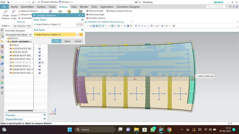
L = Roof strength in X- Direction [mm] (Roof dimension in 0 – Y)
R = Roof curvature
R = 2(Rx*Ry) / (Rx + Ry)
Rx = X Curvature
Ry = Y curvature
t = Roof plate thickness [mm]
I = Bow Roof span [mm]
Judgement Condition: OK < 2.7 > 3.1
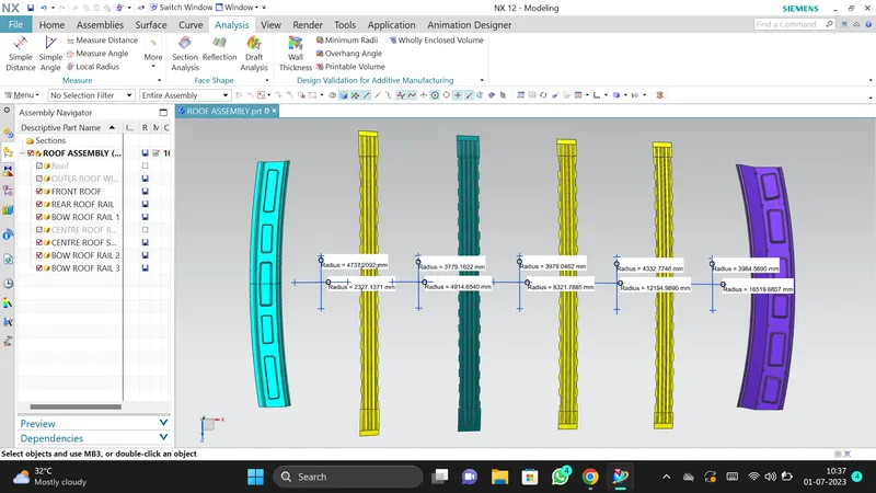
TOP VALUES----->Rx
BOTTOM VALUES----->Ry
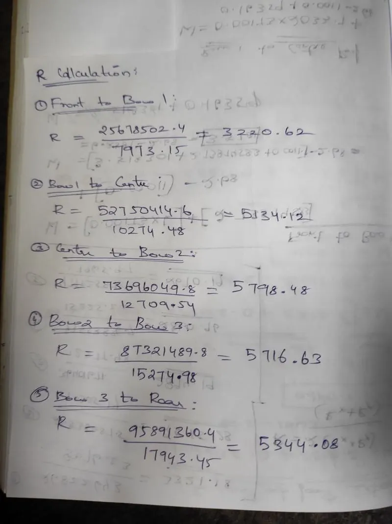
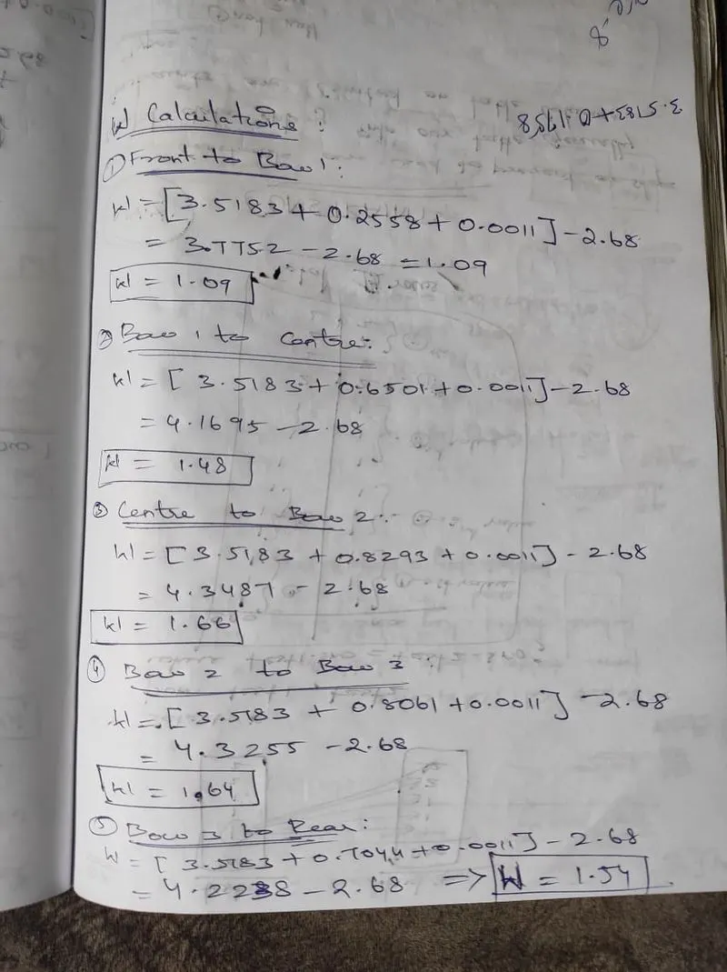
Calculation:
| S.NO | BOW ROOFS | L | t | Rx | Ry | R | (R^2)/t | I | W |
CONDITION |
| 1 | FRONT ROOF TO BOW ROOF 1 | 2033.7 | 0.75 | 5734.01 | 2239.14 | 3220.62 | 13829857.6 | 301.63 | 1.09 | OK |
| 2 | BOW ROOF 1 TO CENTRE ROOF | 2033.7 | 0.75 | 5263.84 | 5010.64 | 5134.12 | 35145584.3 | 307.07 | 1.48 | OK |
| 3 | CENTRE ROOF TO BOW ROOF 2 | 2033.7 | 0.75 | 4474.59 | 8234.95 | 5798.48 | 44829827.1 | 305.50 | 1.66 | OK |
| 4 | BOW ROOF 2 TO BOW ROOF 3 | 2033.7 | 0.75 | 3807.28 | 11467.70 | 5716.63 | 43573144.8 | 302.08 | 1.64 | OK |
| 5 | BOW ROOF 3 TO REAR ROOF | 2033.7 | 0.75 | 3266.80 | 14676.65 | 5344.08 | 38078921.3 | 302.21 | 1.54 | OK |
To find out
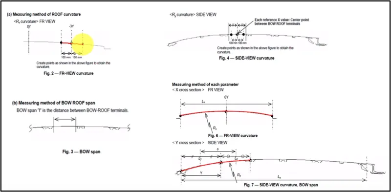
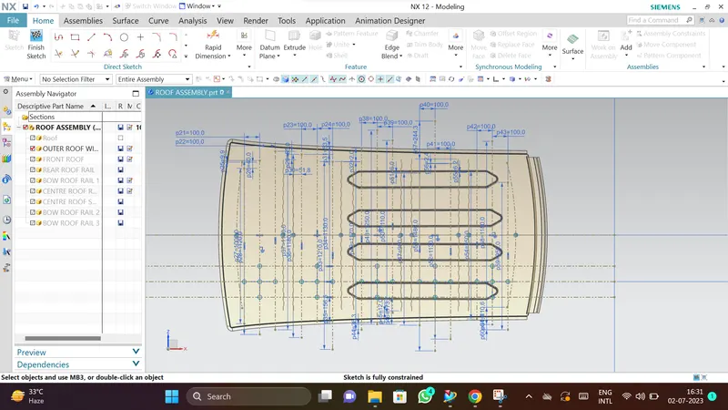
- Create a sketch on Top roof and draw a horizontal line at a center.
- Then offset this line below 300mm and called it as _3y line.
- From the _3y line offset 100 mm above and below and convert all these line into reference line.
- Draw the vertical lines at the middle of each reinforcements and offset it at 100 mm both sides.
- Intersection point is created where the lines are met.
- Project there points the outer roof panel.
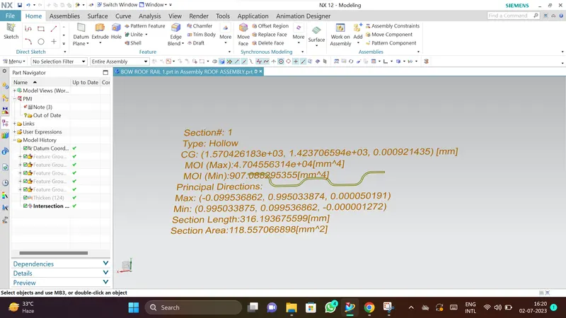
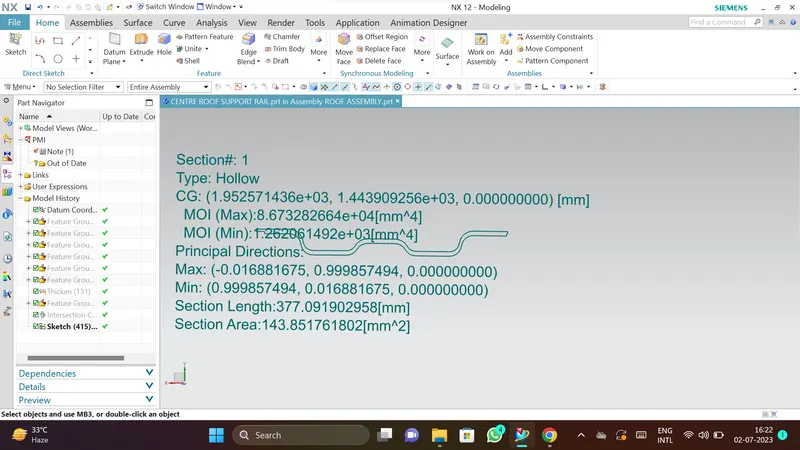
MOMENT OF INERTIA ANALYSIS OF BOW ROOFS:
Here we are taking minimum moment of inertia for calculations.
BOW ROOF 1:
MOI MINIMUM=907.08
CENTRE ROOF WITH SUPPORT RAIL :
MOI MINIMUM=1262.06
BOW ROOF 2:
MOI MINIMUM=439.87
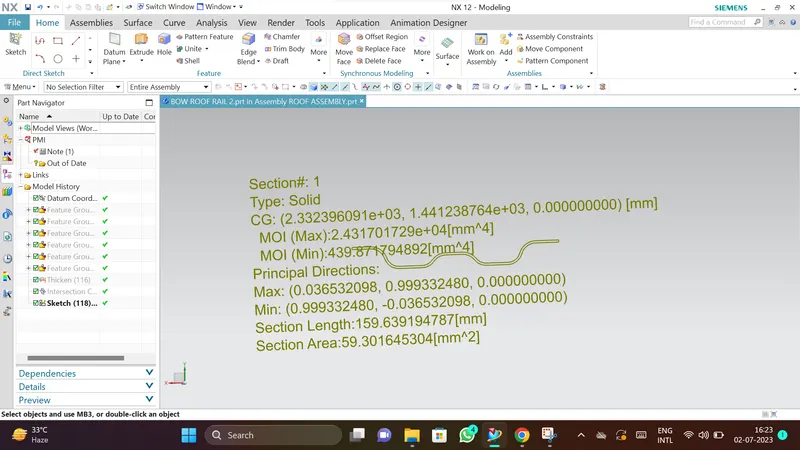
BOW ROOF 3:
MOI MINIMUM=438.09
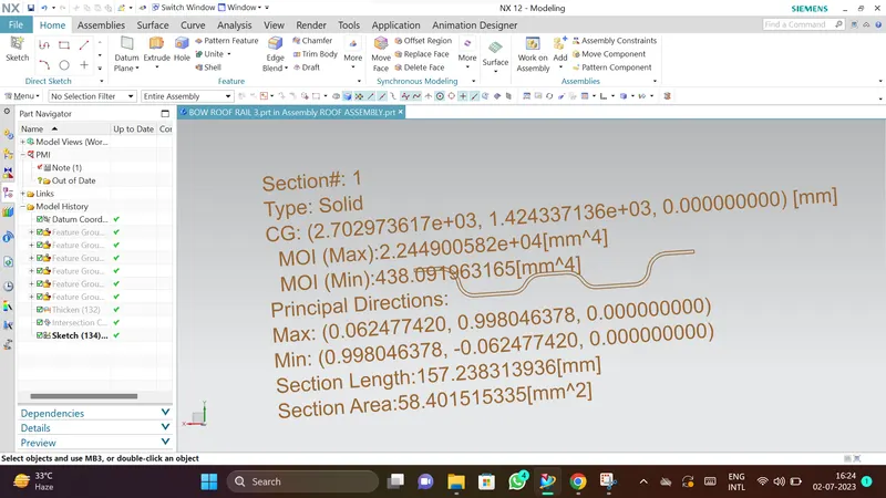
SNOW LOAD CONDITION:

This test is done to know how the roof is behaving when there is a snow over. Normally due to the snow weight the dent will happen. But the roof should be designed in such a way that when the snow is removal the roof should go it its original position. This basic requirement for snow load criteria.
| Qr = [Iy x t2]/ [α x s x [(Rx + Ry) / 2] 2 x 10⁻⁸] |
Where
α= My x L x 2 x 10-12, My = Y (Ly- Y)
Judgment Condition = Qr > 3.1
250 < s < 380
T = Roof plate thickness [mm]
Ly= Distance between the front and rear roof rails on the vehicle along with 0Y [mm]
Length of roof panel with the center point between Roof rail front\Rear as the reference point of the front and the rear.
Lx = Distance between the left and right end of the roof on the Roof Bow [mm]
Width of the roof panel exposed on the surface.
Y = Distance front Roof Rail to Roof BOW [mm]
S = Distance for which roof Bow bears divided load [mm]
S = L ½ + L2/2
Iy = Geometrical moment of inertia of Roof Bow (Y Cross section) [mm4]
Rx = Lateral direction curvature radius of roof panel Y cross section on Roof BOW [mm]
Roof panel curvature radius of the length Lx in front view
Ry = Longitudinal Direction curvature radius of the roof panel X cross section on Roof Bow [mm]
TOP VALUES----->Rx
BOTTOM VALUES----->Ry
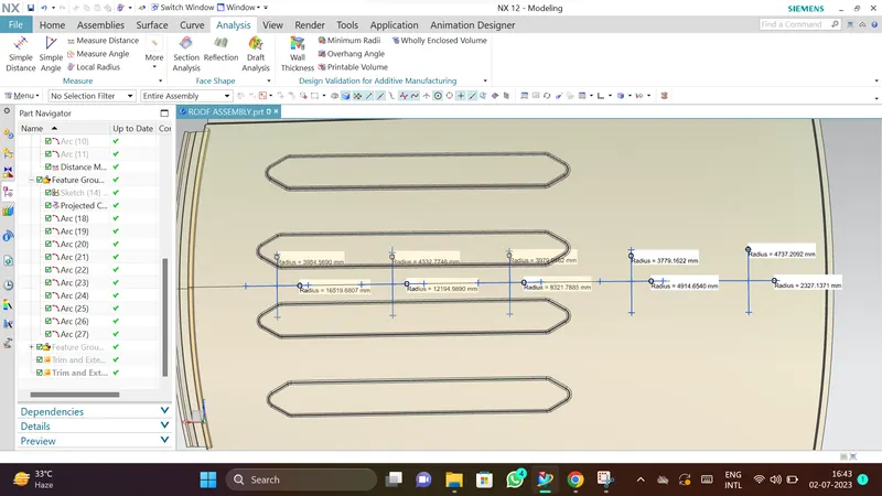
CALCULATION:
| S.NO | ROOFS | L | t | Rx | Ry | Lx | Ly | Y |
| 1 | FRONT TO BOW ROOF 1 | 2033.7 | 0.75 | 4737.20 | 2327.13 | 1148.62 | 1946.40 | 389.91 |
| 2 | BOW ROOF 1 TO CENTRE ROOF | 2033.7 | 0.75 | 3779.16 | 4914.65 | 1102.25 | 1946.40 | 771.04 |
| 3 | CENTRE TO BOW ROOF2 | 2033.7 | 0.75 | 3979.04 | 8321.78 | 1074.59 | 1946.40 | 1152.17 |
| 4 | BOW ROOF 2 TO BOW ROOF 3 | 2033.7 | 0.75 | 4332.77 | 12194.98 | 1057.76 | 1946.40 | 1522.89 |
| 5 | BOW ROOF 3 TO REAR ROOF | 2033.7 | 0.75 | 3984.56 | 16519.68 | 1047.11 | 1946.40 | 1946.40 |
| S.NO | L1 | L1/2 | L2 | L2/2 |
s =L1/2+L2/2 |
My | α | Iy | Qr | CONDITION |
| 1 | 389.91 | 194.95 | 381.13 | 190.56 | 385.51 | 606891.01 | 0.8006 | 907.08 | 13.25 |
OK |
| 2 | 381.13 | 190.56 | 381.12 | 190.56 | 381.12 | 906249.57 | 1.1010 | 1262.02 | 9.95 | OK |
| 3 | 381.12 | 190.56 | 370.72 | 185.36 | 375.92 | 915087.97 | 1.0566 | 439.87 | 1.646 | NG |
| 4 | 370.72 | 185.36 | 423.50 | 211.75 | 397.11 | 644959.14 | 0.7216 | 438.09 | 1.259 | NG |
| 5 | 423.50 | 211.75 | NA | NA | NA | NA | NA | NA | NA | NA |
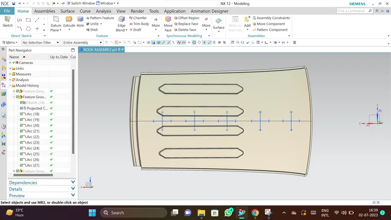
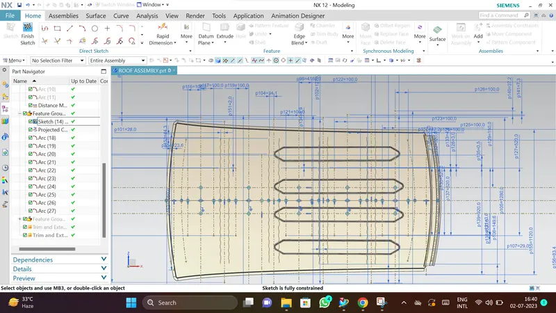
Qr CALCULATION:
To find that
- Create a sketch on Top roof and draw a horizontal line at a center.
- Offset this line to 100 mm on both sides. Convert all these line into reference line.
- Draw the vertical lines at the middle of each reinforcements and offset it at 100 mm both sides.
- Intersection point is created where the lines are met.
- Project there points the outer roof panel.
WHAT IF NG:
STEP 1:Try to provide embosses on top surface of the roof.so here i have provided the embosses even though i got two values that are not satisfying the Qr condition.But two values satisfied the Qr conditions
Qr>3.1
WHAT IF AGAIN NG:
STEP2:If we are getting again NG we have to make trial and error methods for the radius of curvature values.One important point is curvature value should be either gradually increasing or decreasing.But it should not be like sudeen high or drop values.
(OR)
we should should interact with styling team about the concern we can share our value.They will check if it is possible or they will come up with their own suitable values.
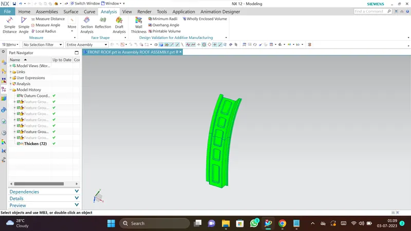
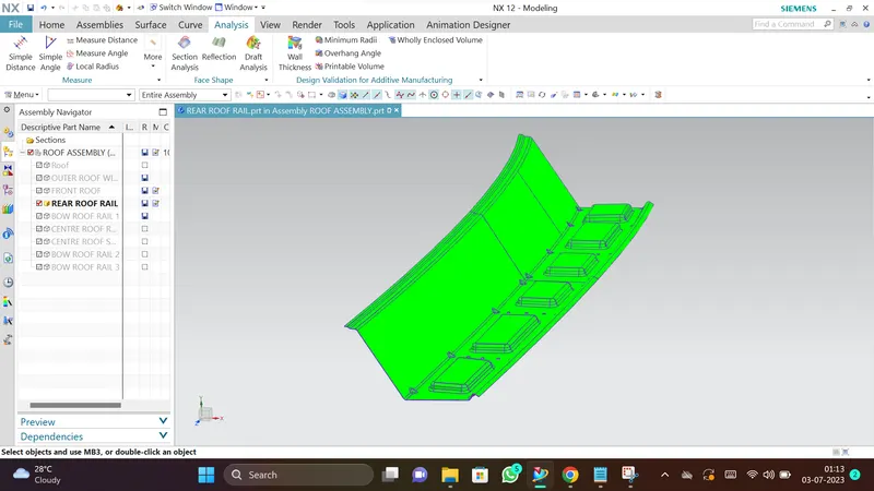
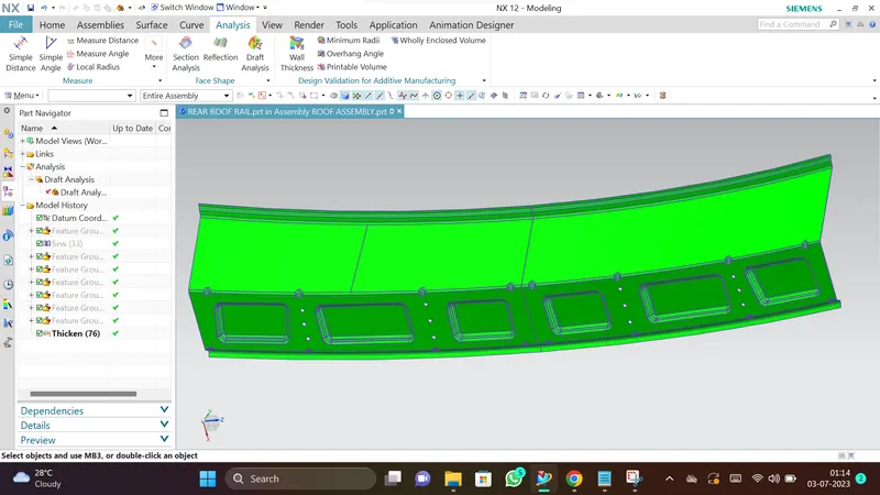
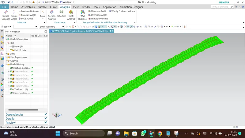
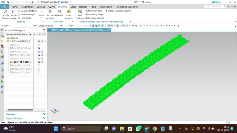
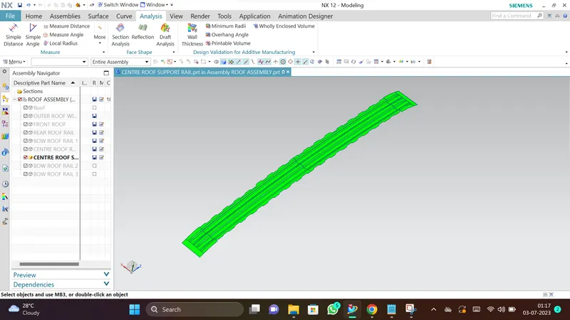
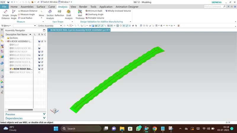
DRAFT ANALYSIS:
FRONT:
REAR:
BOW 1:
CENTRE WITH SUPPORT RAIL:
BOW 2:
BOW 3:
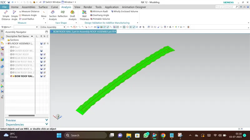
FINAL ASSEMBLY :
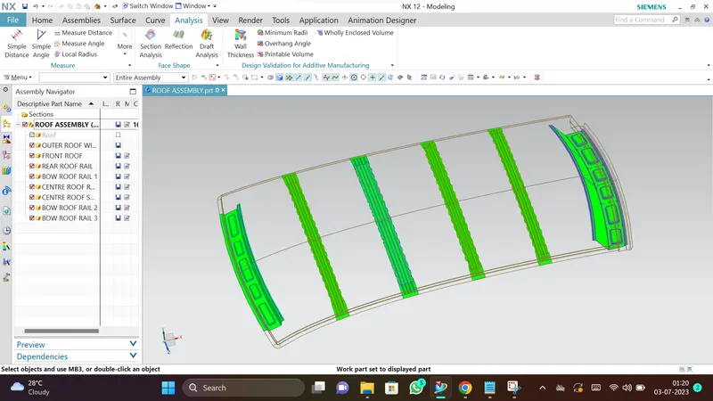
CONCLUSION:
I got outer roof skin data as input.By using it I created the Roof assembly consist of Front roof,Rear roof,Bow roof 1,Bow roof 2,Bow roof 3,Centre roof with support rail.Also we have founded the Heat distortion criteria and Snow load criteria.Draft Analysis also made whether the roof is meeting minimum draft value of 7degree.Also I have attached Zip file for the reference.