Roof Design
Roof Design
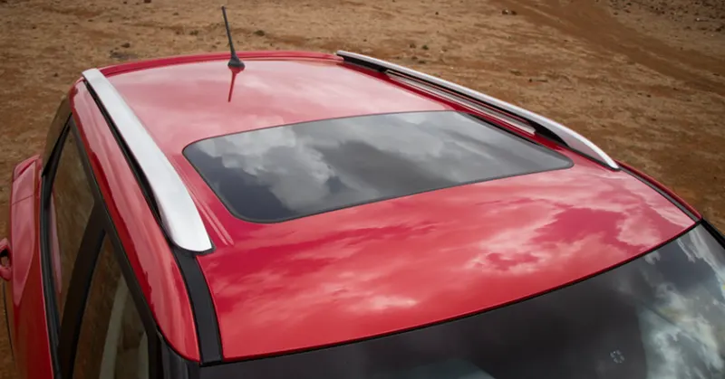
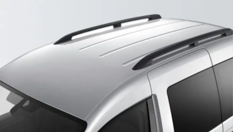
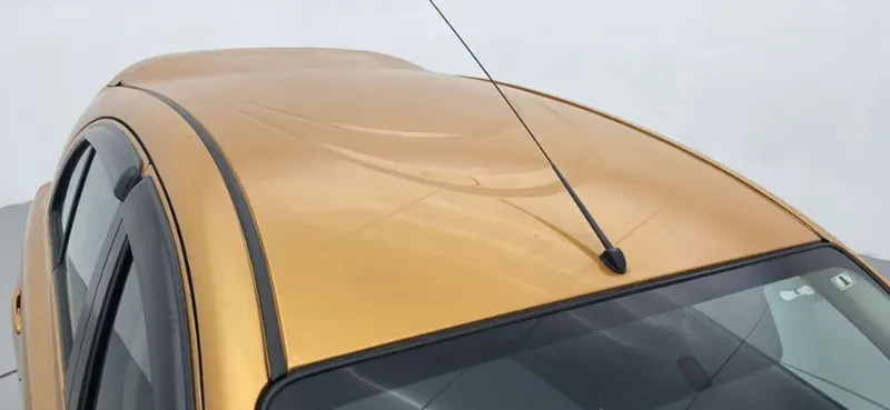
Roof of a vehicle is the portion that sits above the passenger compartment, and which will protect the passengers from sun, wind, rain, and other external elements. Roof is made of sheet metal, and integral to the design, strength, and style of the vehicle. The roof will be supported by A, B and C pilers at each side. Front win shield glass of vehicle is attached to roof with suitable rubber beadings at the front. And at the back, rear door will be opening from the roof end. Various reinforcements will be provided for the roof and additional reinforcements in the form of ribs and embossed design are also provided when required. The roof of the vehicle may also have the provision for a sunroof which will be blanked from the main sheet. The roof may also come with necessary roof carrier mounting arrangements.
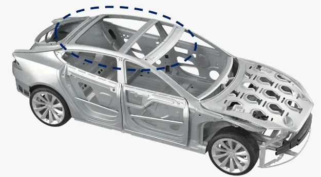
Components of Roof
Major components of roof assembly are following,
- Front Roof Rail
- Rear Roof Rail
- Bow Roof
- Center Roof Rail
- Roof Top
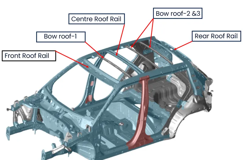
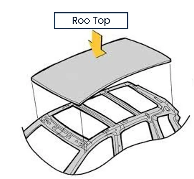
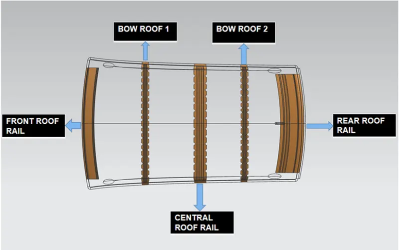
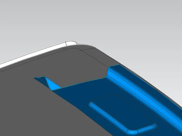
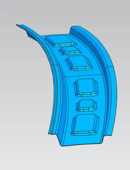
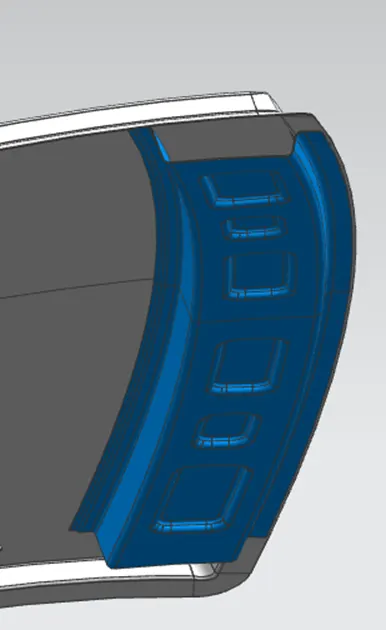
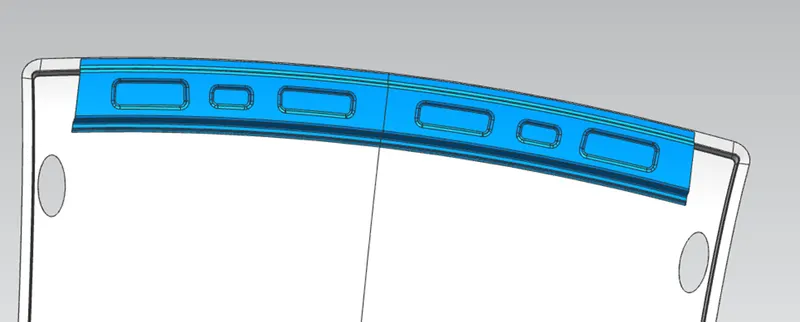
Front Roof Rail
This is located at the front of the roof and to which the wind shield of the vehicle is joined. While designing the front roof rail both visibility criteria and the head room clearance of the passenger must be taken into consideration. One end of the rail is joined using spot welding while the other end is joined with the roof using mastic sealants for increased strengthof this part and the overall strength of the roof assembly.
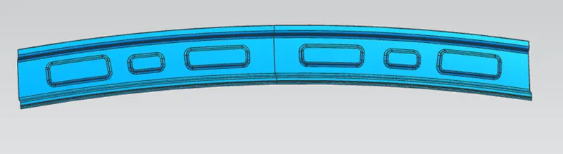
Rear Roof Rail
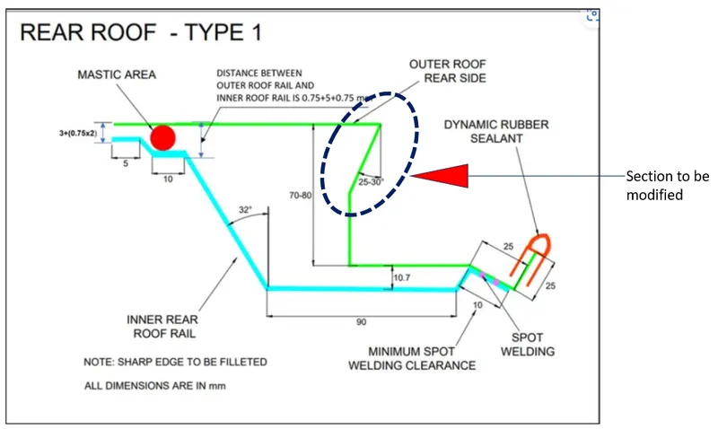
This is located at the back of the roof and to which the hatch door is attached. Design of backdoor and rearward visibility must be taken into consideration while designing the rear roof rail.
Bow Roofs
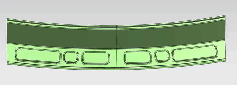
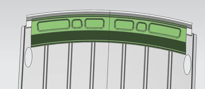
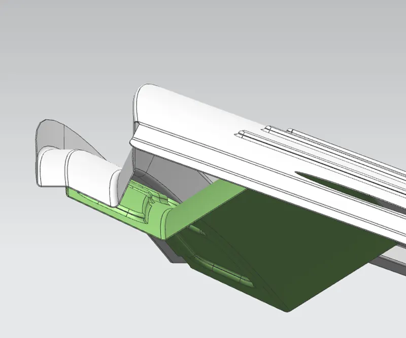
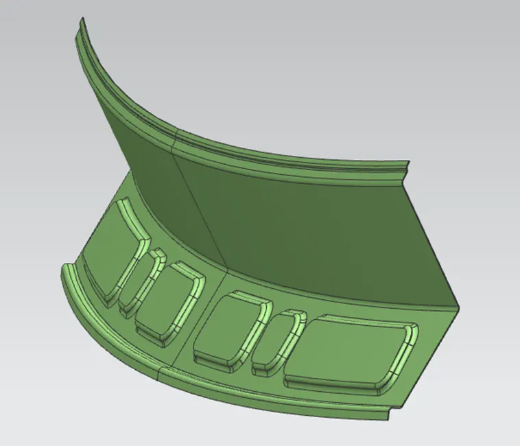
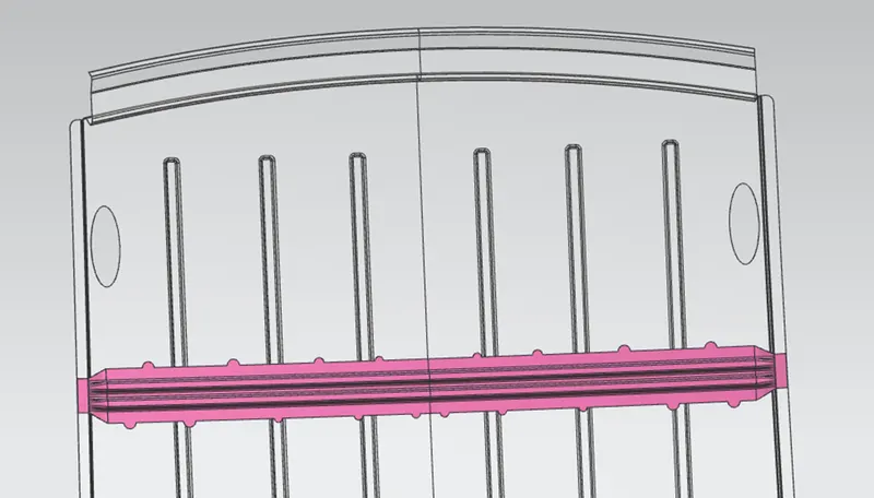
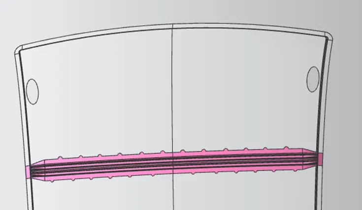
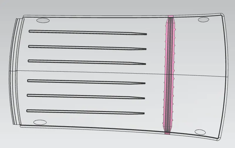
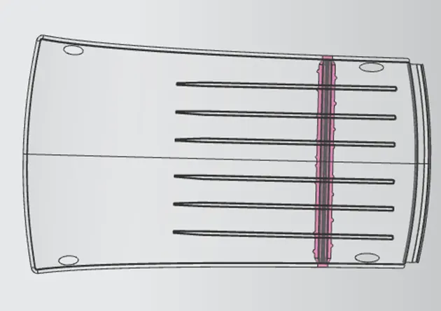
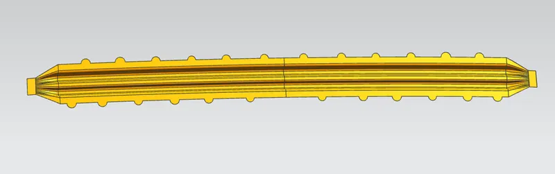
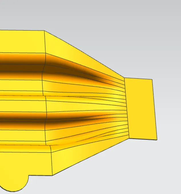
Bow roofs are additional stiffening elements for the roof assembly in order to increase the strength and so that it can meet the regulations and crash norms. Both ends of the bow roof are joined together using mastic sealants to increase strength. Based on various criteria such as length and curvature of roof area strength requirements more than one bow roofs are used in roof assembly.

Center Roof Rail
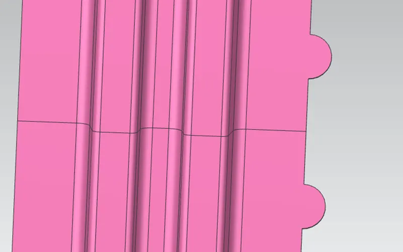
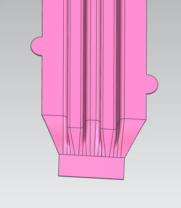
Roof assembly consist of a center roof rail in between front and rear roof rails approximately at th mid of the roof.
Centre Roof rail or the reinforcement center is located at the center of the roof . The cross section of this is more than that of bow roofs since it needs to provide more strength to the roof. Both ends of center roof rail are joined together using mastic sealants.
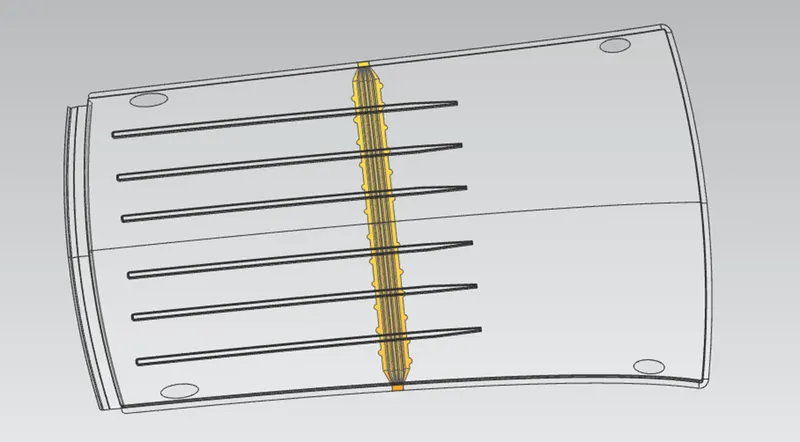
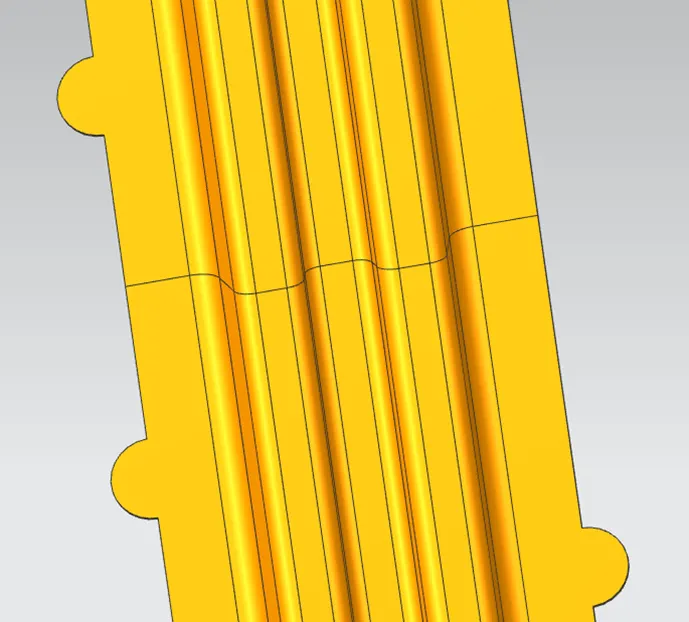
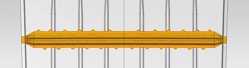
Bow–Roof Position Calculations
Heat Distortion condition
Prediction Formula
W = [1.73 x 10^(-3) x L] + [1.85 x 10^(-8) x (R^2)/t] + [ 1.10x10^(-3) x l] - 2.68
Where,
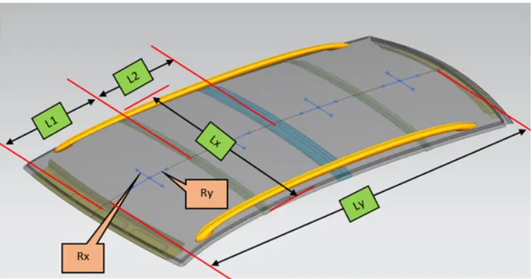
L = Roof Length in X-Direction[mm](Roof dimension in 0-Y)
R = Roof curvature
R = 2(Rx*Ry)/(Rx+Ry)
Rx = X curvature
Ry = Y curvature
t = Roof plate thickness [mm]
l = Bow Roof Span [mm]
Judgment Condition
OK< 2.7
Calculation
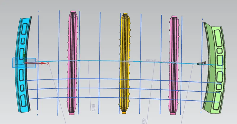
Lines are marked as shown, dimensions are measured and tabulated as shown below.
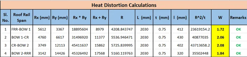
From the table W value is within the limit at all the measured locations, hence the positioning of roofs satisfy the Heat Distortion condition.
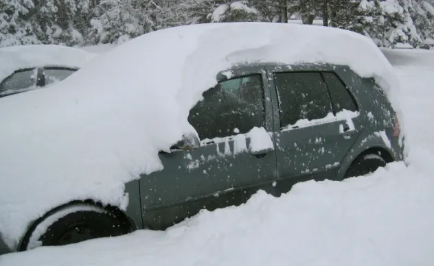
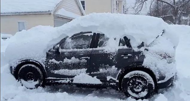
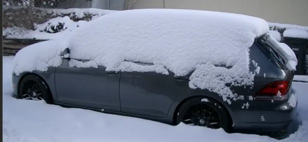
Snow Load
Prediction Formula
Qr = [Iy x t2] / [α x s x [(Rx + Ry)/2]2 x 10-8]
Note: The Qr value given over here is correct. There was a typo error in the formula given in the video.
Where,
α = My x Lx2 x 10-12 , My = Y(Ly-Y)
t = Roof plate thickness [mm]
Ly = Distance between the front and rear roof Rails on the Vehicle along with 0Y[mm]
Length of Roof panel with the center point between Roof rail Front /Rear as the front and rear reference point.
Lx = Distance between the Left and Right end of the roof on the Roof BOW [mm]
The width of the roof panel is exposed on the surface.
Y = Distance front Front Roof Rail to Roof BOW[mm]
s = Distance for which Roof BOW bears divided load [mm]
s = L1/2 + L2/2
Iy = Geometrical moment of inertia of Roof BOW (Y cross-section )[mm4]
Rx = Lateral direction curvature radius of roof panel Y cross-section on Roof BOW [mm]
Roof panel curvature Radius of the Length Lx in Front view
Ry = Longitudinal Direction curvature radius of the Roof panel X cross-section on Roof BOW [mm]
Roof panel X curvature radius of length s in Side view
Judgment condition
Qr ≥ 3.1
250 ≤ s ≤ 380
Calculation
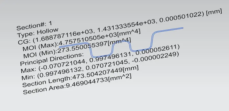
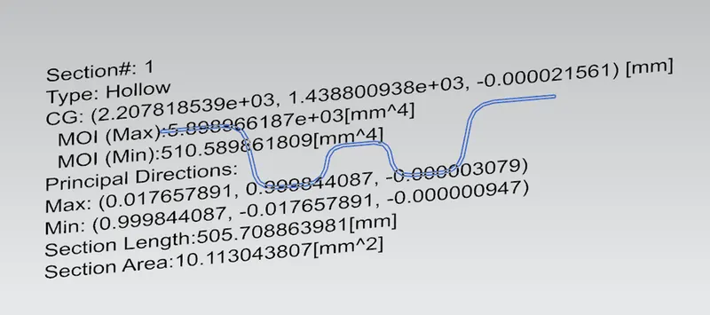
Iy values of each sections are measured
- Bow Roof-1
- Center Roof Rail
- Bow Roof-2
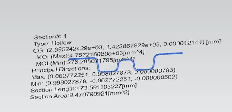
Required lines are marked as shown, dimensions are measured and tabulated as shown below.
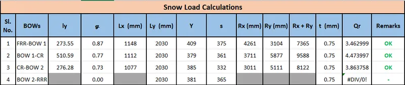
From the table Qr and s values are within the limit at all the measured locations, hence the positioning of roofs satisfy the snow load condition.
Draft Analysis
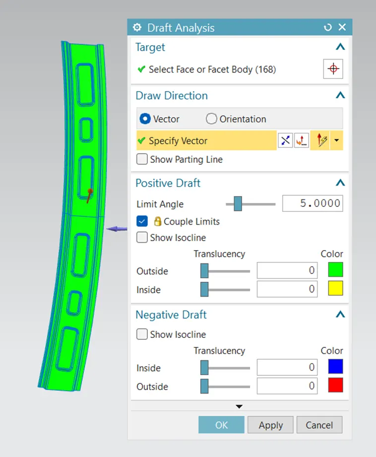
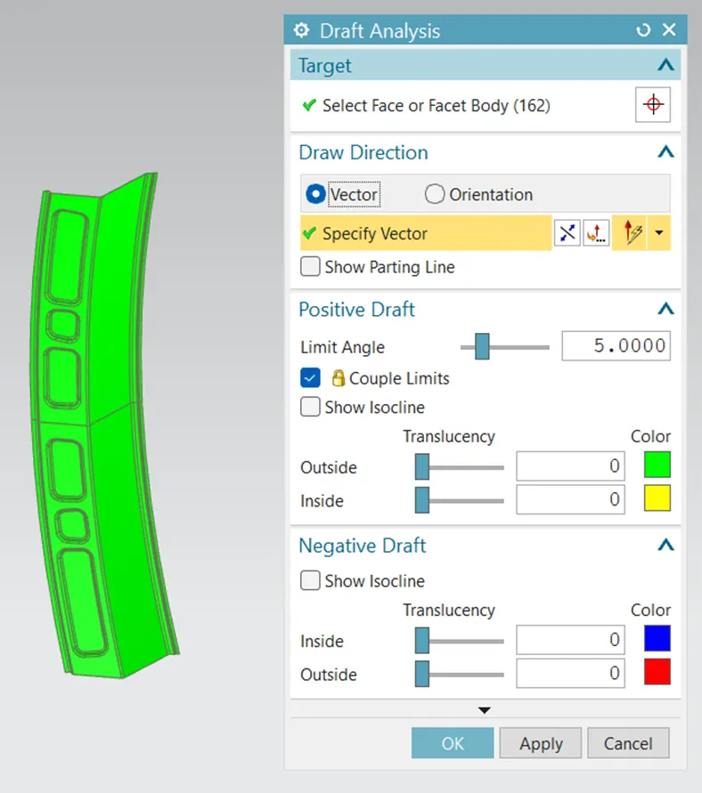
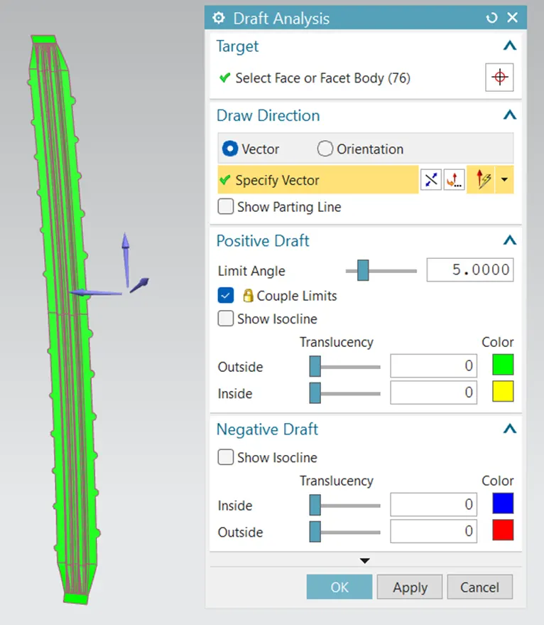
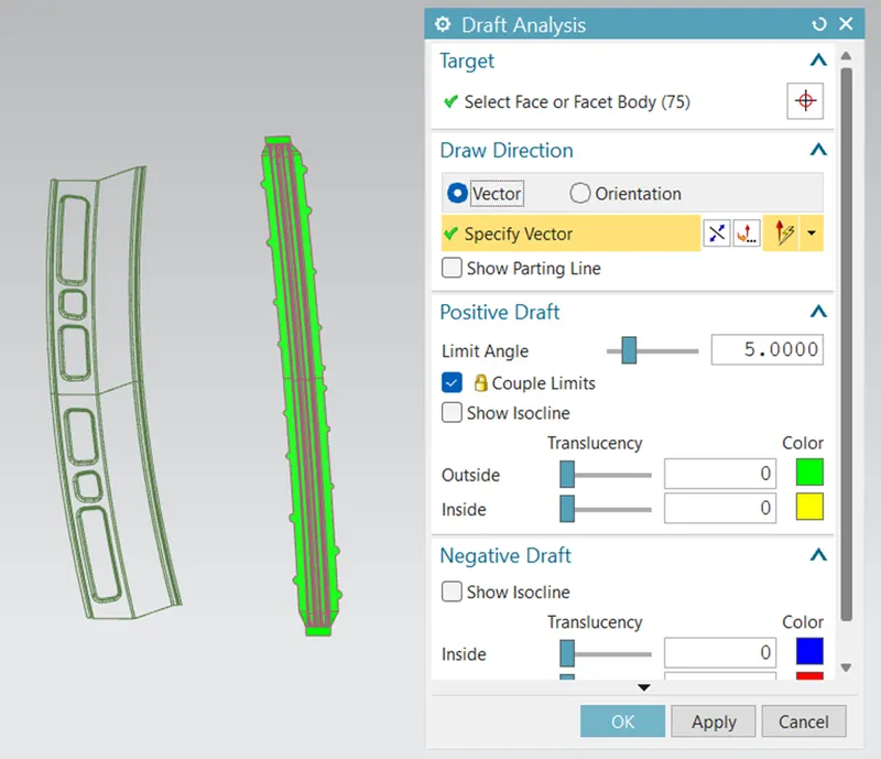
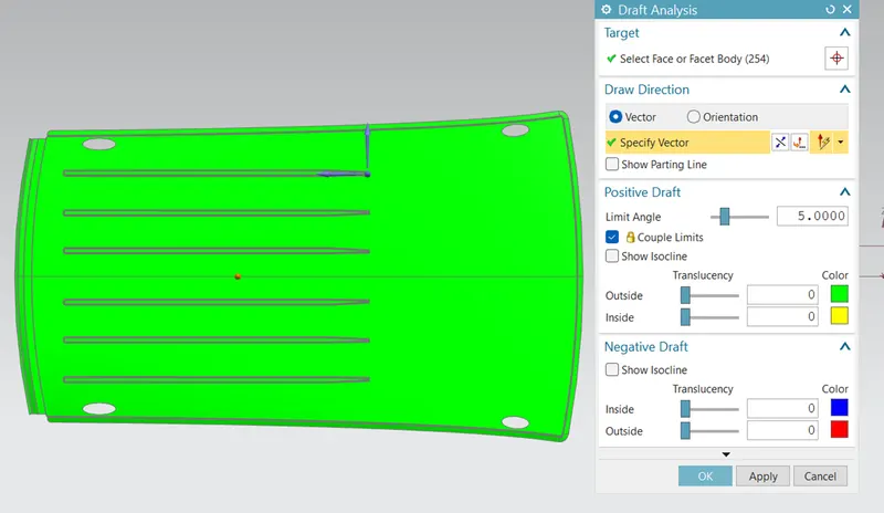
Draft analysis done for each part of the roof assembly.
Images are attached below.
Front Roof Rail
Rear Roof Rail
Center Roof Rail
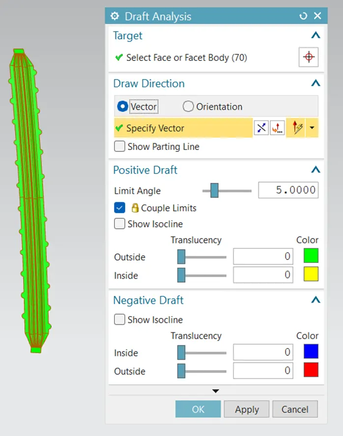
Bow Roof 1 & 2
Roof Area
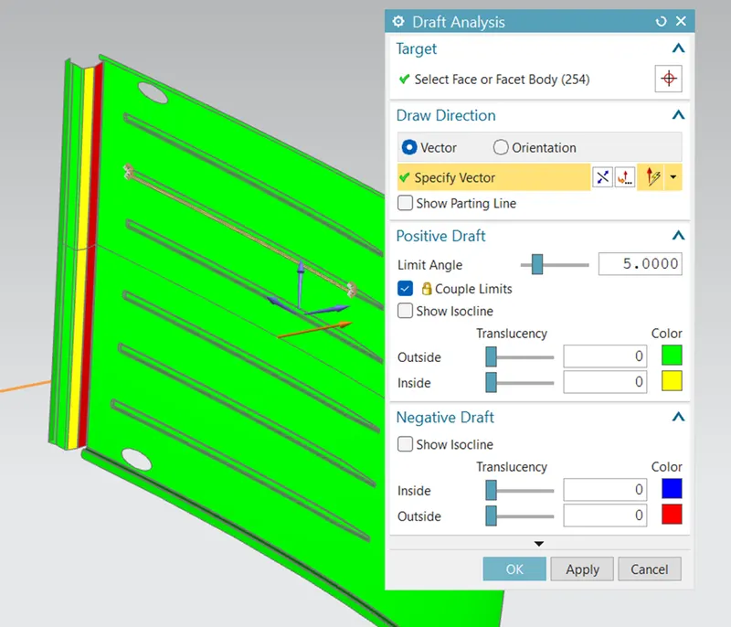
Rear dip area with inward angle of 25-30deg highlighted in red as shown above.
This area in the input section marked below have to be either modified or necessary changes have to made in tooling direction.
Manufacturing Techniques
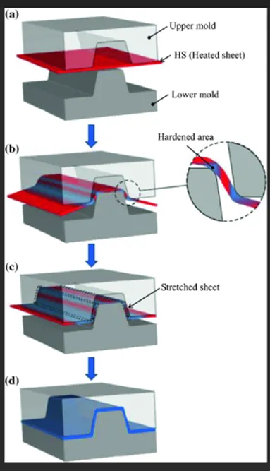
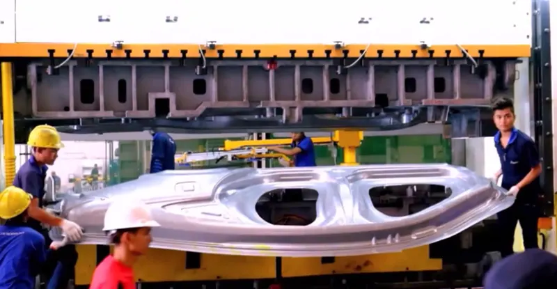
Car panels are manufactured by metal forming processes. The process begins with a sheet metal blank, a quantity of metal in some standard form that will undergo the change in shape. The blank becomes the workpiece -- the piece of metal to be reshaped -- in the process. For automotive metal forming, the blank can be stamped, cut or bent into a shape needed for an automobile's body. Alternatively, it can be a solid block of metal in a cubical or lens-like shape. Following are the widely used processes for roof panels and roof rails.
Stamping
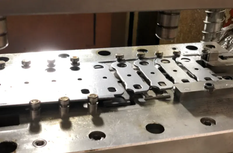
In stamping, a device called a stamping press is used with a series of dies to cut and form metal into various shapes.
Drawing
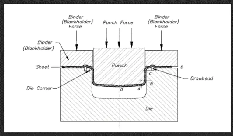
In drawing, the sheet metal is forced against a die that has been cut into the three-dimensional, often curved shape that the sheet metal is to take on. In effect, the die is used as a mold for the metal. This technique can produce relatively complex shapes. Once again, pressure is applied to the workpiece using a hydraulically or mechanically operated punch.
Roof Assembly
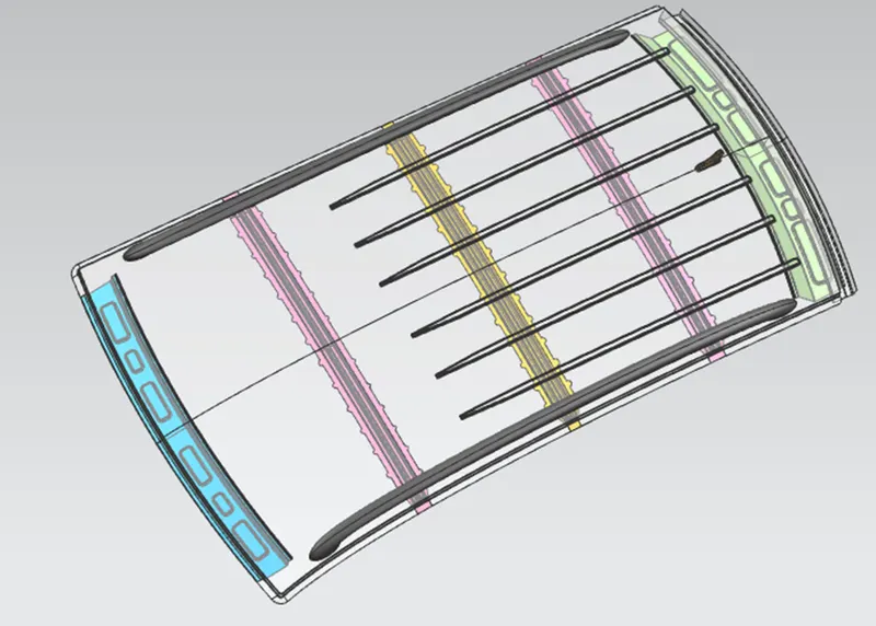
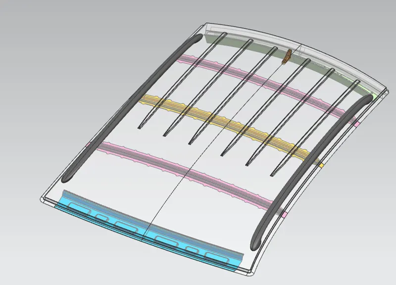
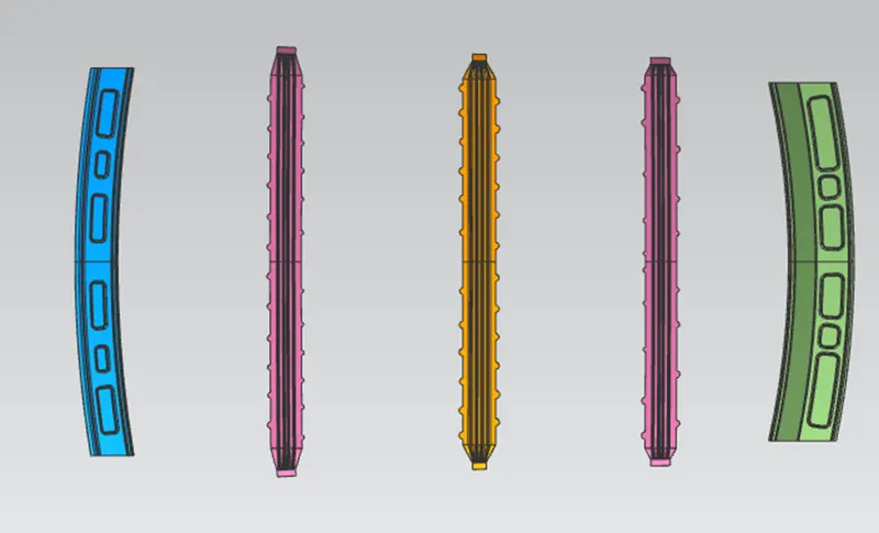
Roof assembly completed with the given roof styling and sections of each parts. Designed roof verified against both heat distortion condition and snow load condition. Draft analysis done for each parts.
Sebin Baby