Roof Design
ROOF DESIGN
Aim:
To design & develop the Roof of a car with its components by following the master section and design parameters.
Objective:
- To develop the essential flanges and reinforcements using roof styling as input.
- To do a curvature study on the roof and perform calculations to determine the position of the Bow-roof.
- To determine the Heat Distortion Criteria of the car's roof.
- To find the section modulus on the O-Y section of the roof and also for all the components of it.
- To determine the Snow Load Criteria for a car's roof.
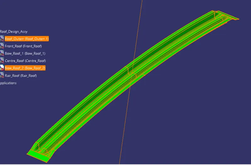
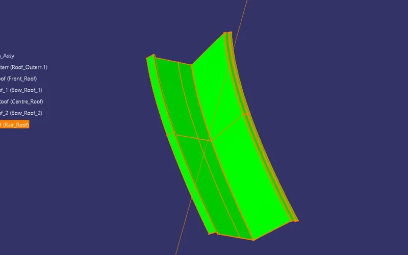
- To perform Draft Analysis on the final CAD model of the roof.
Introduction:
Car's Roof:
An automobile roof or car is the top portion of an automobile that sits above the passenger compartment, protecting the vehicle occupants from sun, wind, rain, and other external elements.
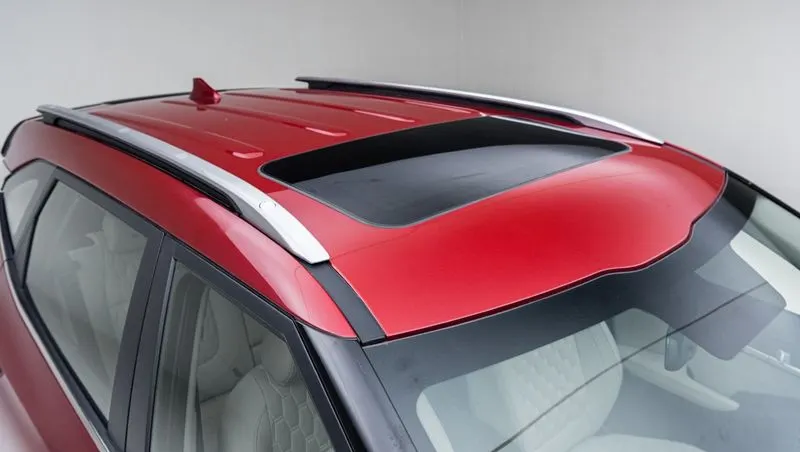
The roof of a car or other vehicle is the top part of it, which protects passengers or goods from the weather. The roof also protects the passenger from any injury when the car gets crashed or is rolled over or something heavy falls on the roof.
OBJECTIVE
The mian objective of this project is to understand the design process to design the roof with all the roof rails and to understand the calculations behind it. We also get to learn about the different tools used in CATIA V5 for designing.
METHODOLOGY
We get the model of the roof of the from the styling team. Then we will have to do all the engineering work. We create the ditch area for the roof and also the roof bows and roof rails for the roof which would we designed by us considering all the safety norms and regulations.
DESIGN CONSIDERATION RULES
They are:-
-
Visibility criteria
-
Head clearance
-
Curvature study
-
Hear distortion and snow load criteria
-
Draft analysis.
In design point of view, it is hard to create the roof design. Because for designing roof we have to create no of support rails for enough strength to withstand the load. Bow roofs are primarily fixed in flatter region to enhance strength. Front roof and rear roof rails are fixed to the ditch area using spot weld operation. And front, rear bow roof and center roof rails are fixed to roof using mastic sealants. We don’t want so much gap between roof rails and bow roof area. So, we reducing the NVH issues.
According to conditions we have to decide the number of bows which is used for support the roof. Designing the front roof rail, bow roof rails as well as rear roof rail according to the given master section. After completeing design need to calculate the parameters required for heat distortion criteria and cchecking the values of distortion in the roof are within range or not. Also we have to do iteration for the snow load condition to check the strenth of the roof.
COMPONENTS OF CAR'S ROOF
DESIGN OF
- Car Roof Outer Panel
- Front/Rear/Central Roof Rails
- Bow Roof
Here in above picture they are having 3 bow roofs and 1 centre roof it depends on roof and some criteria so in our project we are having FRONT ROOF RAIL , BOW ROOF 1 , CENTR ROOF RAIL , BOW ROOF 2 , RAIR ROOF RAIL AND ROOF OUTER.
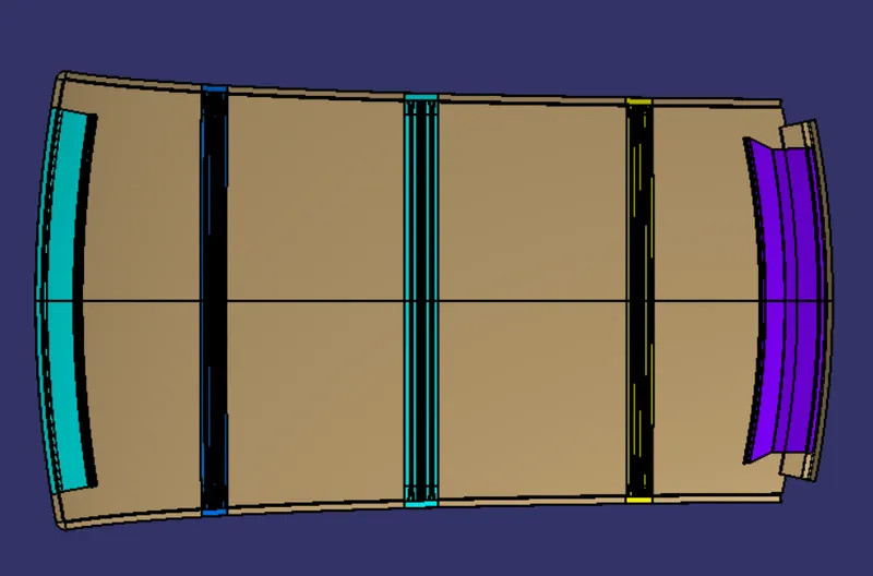
Front Roof rail:
This is the reinforcement provided at front. This part is joined to BIW body and windshield. Visibility criteria is taken in account for joining it with windshield. It is fixed to BIW with spot welds and roof surface is attached with the help of mastic sealants. A draft angle is provided for deep drawing operation. Draft analysis is also done on the section to check its manufacturing ability.
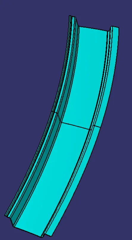
Bow roof 1:
It is an additional reinforcement provided to increase the strength of the roof. It is fixed with roof body with mastic sealants.
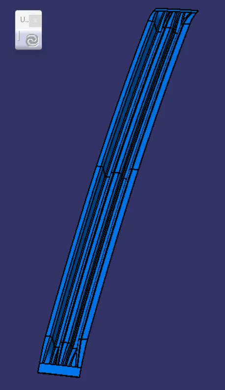
Centre rail roof:
Centre rail roof can be considered as reinforcement joining the left and right part of the roof. It is fixed to roof by mastic sealants and to BIW by spot welds.
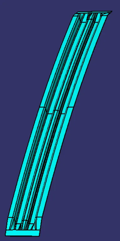
Bow roof 2:
It is similar to the bow roof 1 provided for better strength.
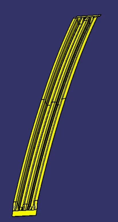
Rear Roof rail:
It is the reinforcement provided at rear side of the roof. Backdoor and bodyside panels are attached with this part. It is also attached with mastic sealants and spot welds.
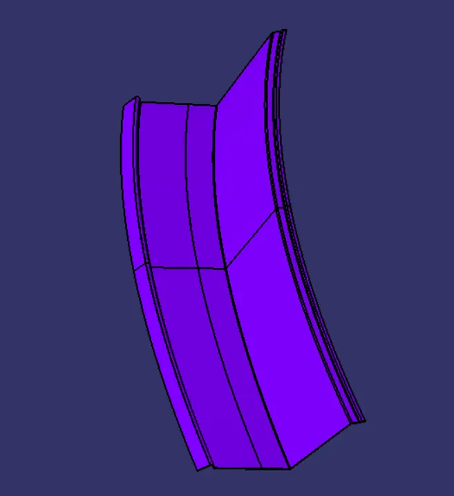
Master Section:
Master sections are the crosssection of 3D model. These master sections are widely used in OEMs and in automotive industries to convey the functional requirements of commodity to the design engineer. It gives the parameters like length, width, height, radius and clearance should be considered while designing the particular part or component.
1) Roof outer panel & front roof rail master section:
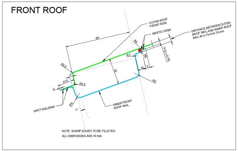
In the above master section the verticle flange is given at 7° followed by the given class A curvature surface. And the distance between the outer roof panel and inner front roof rail is given 32mm. Also the front side the ditch area is given 21.50mm in the outer roof and for the inner front roof rail it is reduced by 2.00mm here at this end there is Spot welding is shown so, there is no any gap between the outer roof and inner front roof rail. Also the blend of the corner dimensions are given at diiferent edges. In the end of the inner front roof rail the 10.00mm and 5.00mm distance horizontal flange are given where the MASTIC Sealant is used. So Area is given for mastic joint is 3.00mm and 5.00mm.
The front roof rail is used as the reinforcement to the roof surface to increase the strength and also used to mount the brackets for some features such as room lamp or map lamp and rear mirror. The depth of the front roof rail is decided based on the visibility criteria line decided for the driver visibility. The width of the front roof rail is decided in such a way that there should be enough headroom clearance between the head of the driver and the end surface of the roof rail to avoid injuries to the person.
2) Bow roof master section:
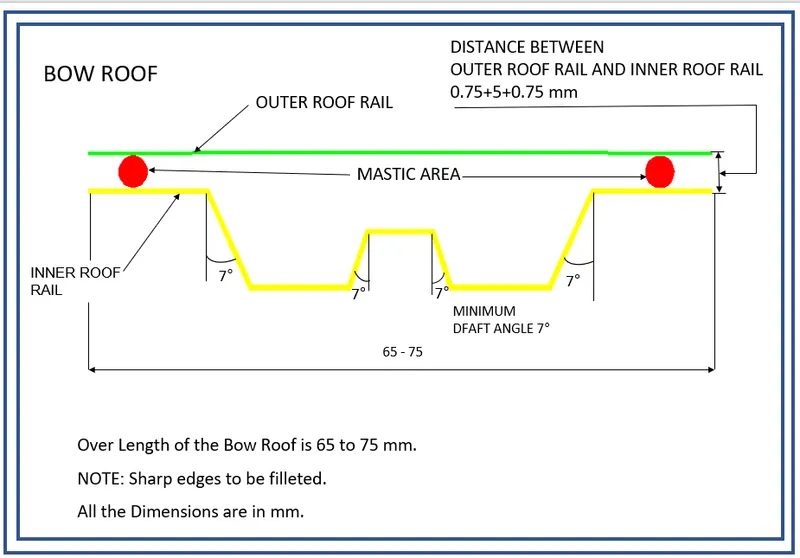
Here, the overall width of the bow roof should lie between 65-75mm and all the embosses have atleast 7° of positive draft with respect to the tooling direction. Then the offset of bow roof outer flange is 0.75+5+0.75mm from the roof outer panel because of the Mastic Area.
3) Center roof master section:
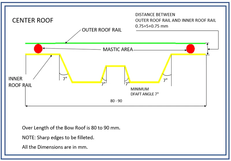
Same as the bow roof, the overall width of the center roof should lie between 80-90mm and all the embosses have atleast 7° of positive draft with respect to the tooling direction. Then the offset of center roof outer flange is 0.75+5+0.75mm from the roof outer panel because of the Mastic Area.
4) Rear roof rail master section:
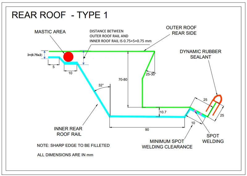
The outer roof panel rear flange should have the negative flange of 25° - 30° draft to accommodate the clearance for back door movements. The overall hight of the rear flange must lie between 70-80mm. The Dimenstions for rear roof rail are offset of (3+0.75+0.75) & (0.75+5+0.75) for front flanges, which is given because of Mastic Area. and the 10.7mm for the offset of center emboss and its width is 90mm. Then the draft angle for emboss connecting the front flange is 32°. Here in the rear area of the rear roof rail is SPOT welded to the outer roof so there is no gap maintain between them at this area.
Procedure:
Open the given model in CATIA V5 that is the styling surface of the car's roof.
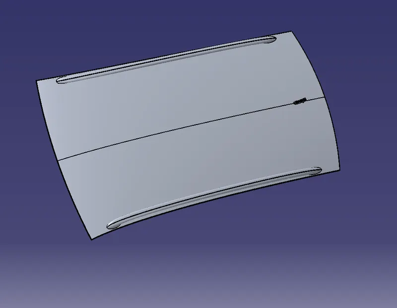
In this challenge, we will be creating the Roof's outer panel, Front roof rail, Rear roof rail, Centre reinforcement and Bow roofs.
Roof Outer Panel:
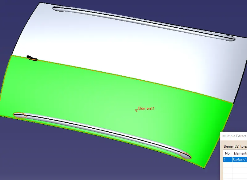
First, we will be extracting the top half portion of the roof surface. Since the roof surface is symmetrical in shape, we can easily work only on half of the portion and reflect it at the end to create the whole roof.
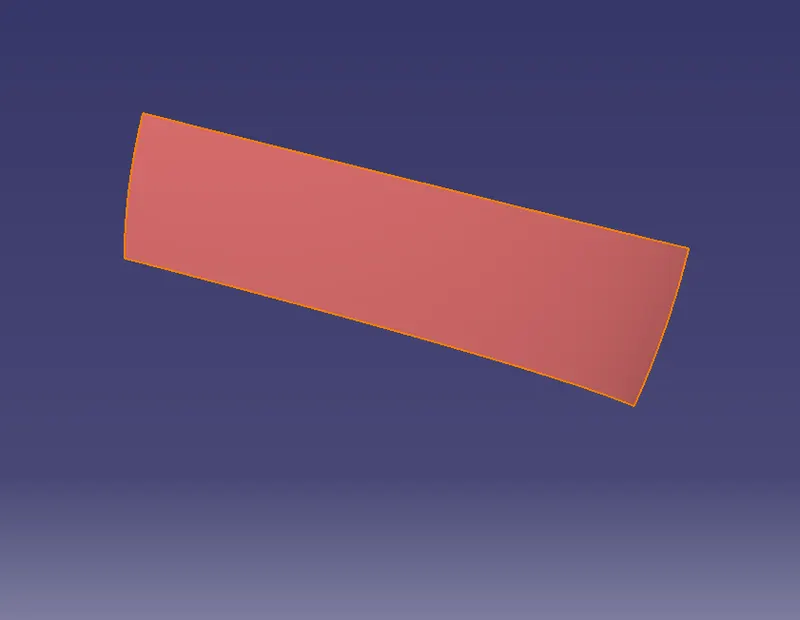
Untrim this surface in order to avoid the holes. Extract the outer boundaries of the original half surface and project it on the untrim surface to get the exact outer edges of the roof.
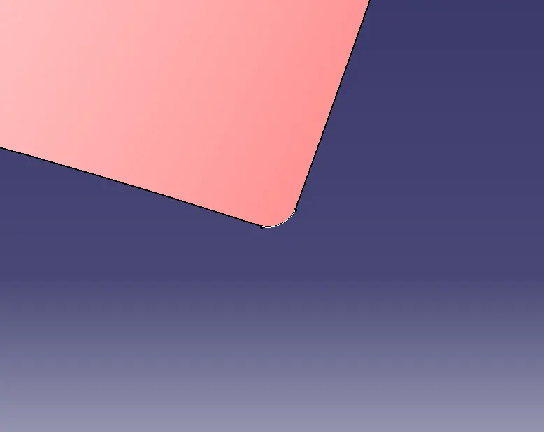
The corners of the roof surface are sharp so using the corner option in CATIA V5 we will be giving a 5mm curve/fillet on those corners.
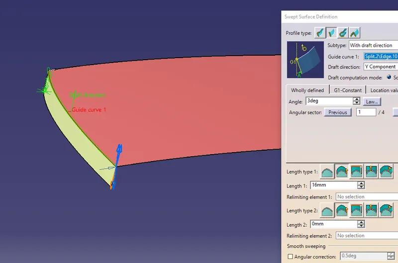
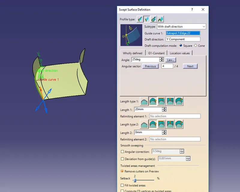
Now we will be creating the flanges by first sweeping the front edge to 3 deg in Y-direction and length as 16mm.
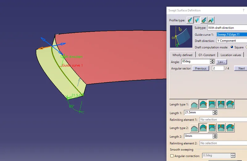
From the edge of the sweep (surface) take another sweep with 65 degrees draft in Y-direction and length as 21.5 mm.
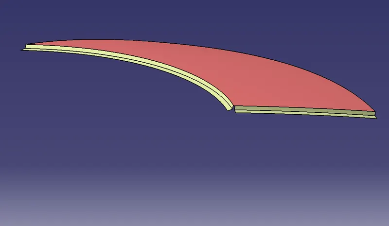
Similarly, by following the same procedure we can create a flange on the other edges as well.
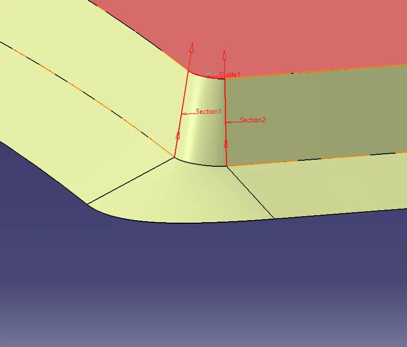
Using the Multi-Section option in CATIA create a surface on the corners by giving guide curves and support of the surfaces.
Join these Surfaces together and give the required fillets.
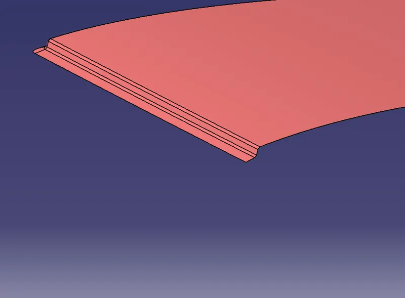
For the Rear end, there should be an additional area that helps to hold the back door without hitting the roof.
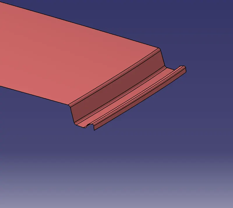
Front Roof Rail:
Following the master section which is given to us as input, we will be creating the Front Roof Rail.
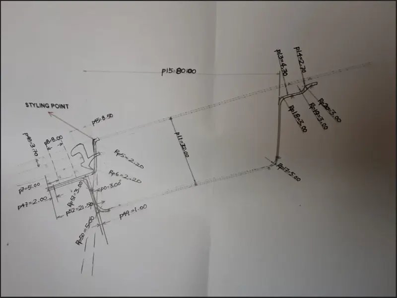
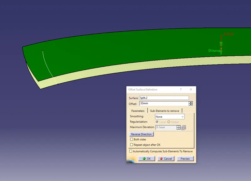
First, offset the top roof surface to 32mm and using a parallel curve offset the edge to 80mm.
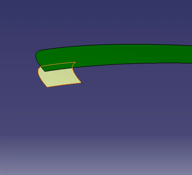
Split the offset surface using this edge. This surface will be now our base surface of the front roof rail.
Sweep the edges and create a surface on both sides of the roof. Make sure to sweep the edges with a draft of more than 7 degrees.
Now to create the left portion (as per the below image) extract & offset the outer roof flange to 1.7mm.
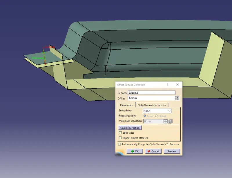
Trim this offset surface with the sweep surface of the front roof rail.
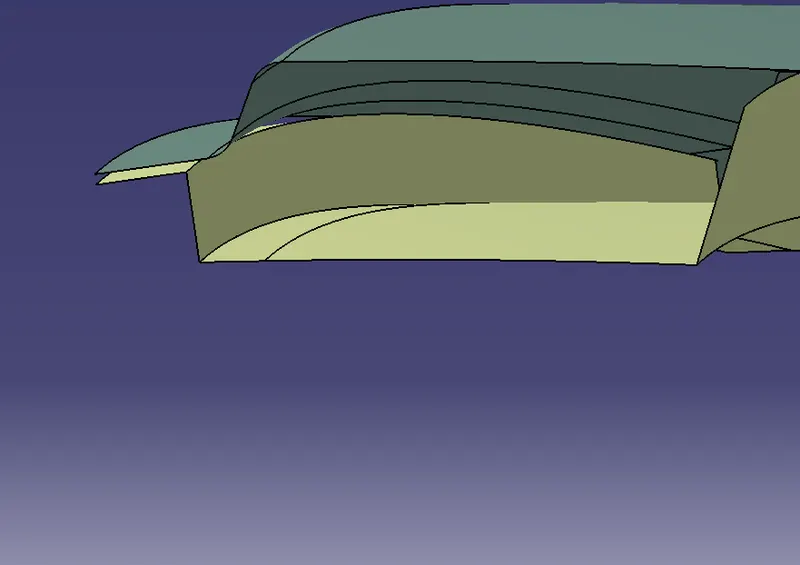
Now to create the right portion (as per the below image) offset the top roof surface to 4.2mm & 6.2mm.
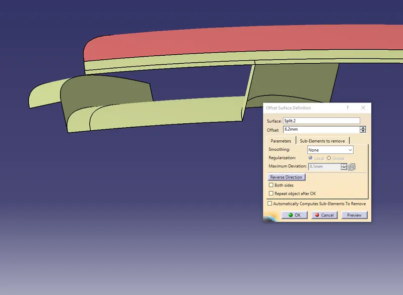
Using the offset curve of 80mm (which we created for the base surface) create another 2 offset curves with a distance of 10mm & 5mm.
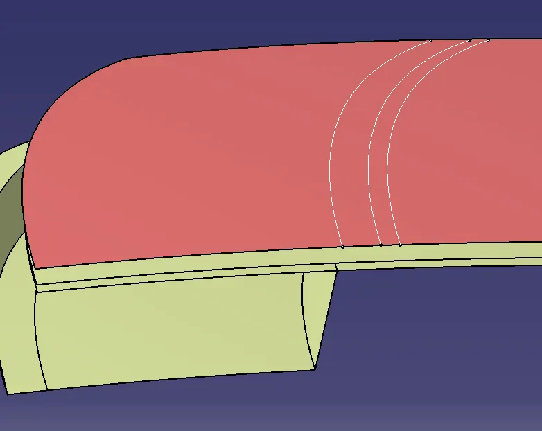
Split the 6.2mm offset surface with the 10mm curve and then split the 4.2mm surface with the 5mm curve respectively.
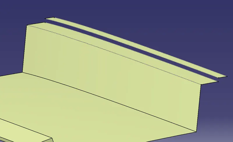
Now join the base surface, 6.2mm surface and 4.2mm surface using blend and give required fillets to all the edges.
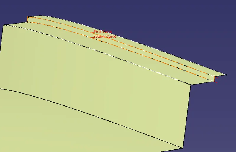
with the similar way we created rair roof alsoand all other also
Solid-Body:
Once all the surfaces are created, use the symmetry option and mirror all the parts (individually) using the XY Plane and join them.
After mirroring all the surfaces successfully, use the thicken option to create the solids with the proper thickness.
The thickness for the Roof Outer Panel, front roof rail and rear roof rail is 0.75mm
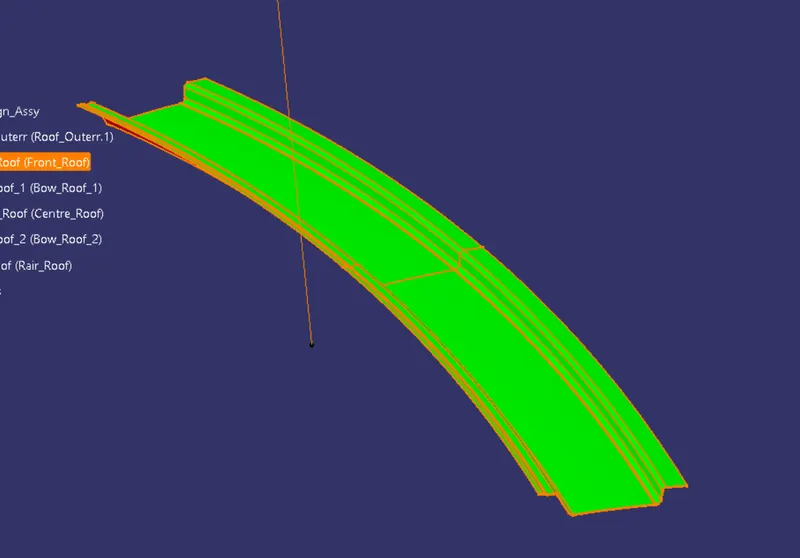
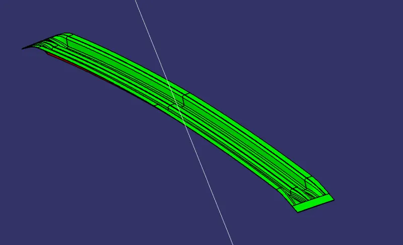
DRAFT ANALYSIS ON FINAL COMPONENTS :-
FRONT ROOF RAIL
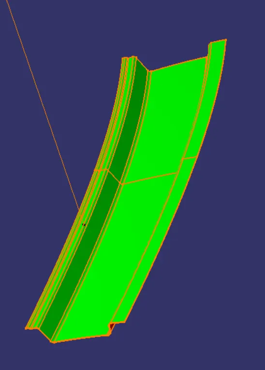
BOW ROOF RAIL 1
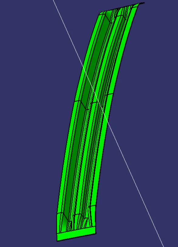
CENTRE ROOF RAIL
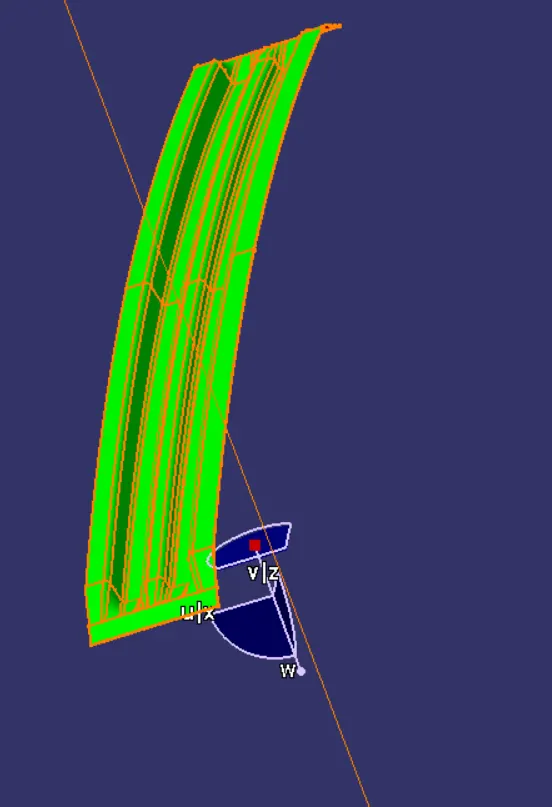
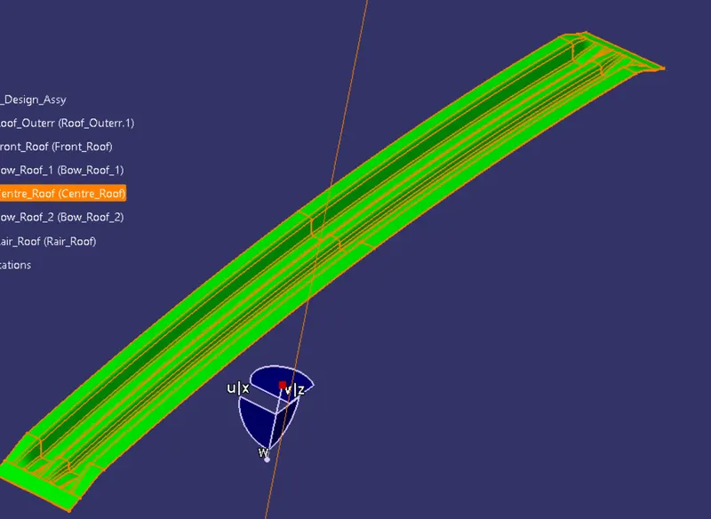
BOW ROOF RAIL 2
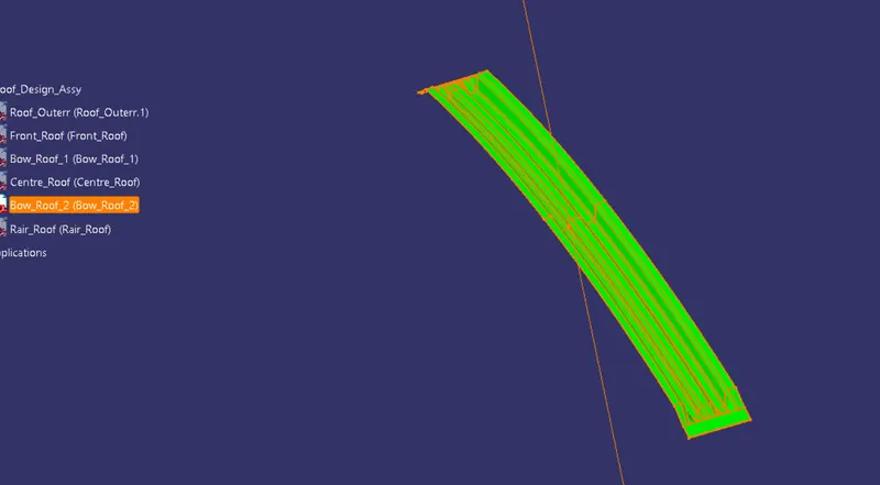
RAIR ROOF RAIL
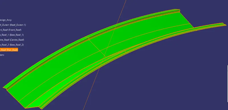
ROOF OUTER
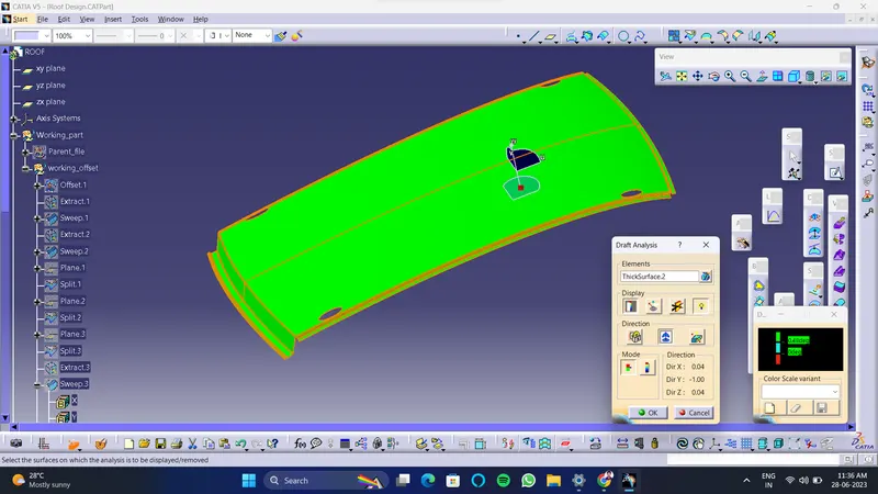
Manufacturing technique:
Here, The car roof is generally manufactures from the sheet metal sheet. In the manufacturing process the stamping process and at some place bending process is done. Also for joining this all sheets there are mastic sealant is used and at some place the spot welding is done. Here, which portion is visible from the outside is joined using mastic sealant and which portion is hide from outside is joined by spot welding process. Emboss is done by punching which is increase the strength of the panel. also some cutout is done for weight loss.
The manufacturing process for car roof parts, comprises the following steps:
By outer board machining process, bar shaped assembly, ring-shaped component processing and roof cant rail processing technology, formed respectively;
Outside plate process: the first step, open straight snips plate: first select applicable cold coiling specification, cold coiling is opened flat; Then according to production material specification, will open cold coiling after flat and be cut into into the iron plate of corresponding size; Finally the iron plate after shear is cleaned to iron filings; The first step, oil pressure, punch press: first iron plate is extended; Secondly to its trimming and punching; Then to its flanging and punching; Finally, after punching completes, it is carried out to the operation of side folding; Completed the making of outside plate;
Bar shaped assembly and ring-shaped component process: the first step, blanking, stamps out iron plate the outline blank of many roof cant rails, a ring-shaped component and a bar shaped assembly; Second step, carries out annular punching to ring-shaped component; Bar shaped assembly and roof cant rail are carried out to bar shaped punching;
Car roof anabolic process: the first step, by a plurality of M6 nuts of a side spot welding of ring-shaped component; By two M6 nuts of bar shaped assembly two ends spot welding; Second step, spots weld bar shaped assembly the opposite side of the corresponding nut of ring-shaped component; And circular groups and the punching of bar shaped assembly are aimed at; The 3rd step, is welded to ring-shaped component the inner side of outside plate; The 4th step, spots weld roof cant rail the inner side of outside plate; Finally car roof integral body is carried out to sanding thorn and ending.
Curvature Study on the Roof:
- Heat Distortion calculation
- Snow Load calculation
Heat Distortion:
Heat distortion is temperature limit above which material cannot be used for structural application. This study is useful to find the where the material starts to soften when exposed to a fixed load at elevated temperature. In order to avoid the bending, damage to the roof based on the heat distortion temperature. This study will provide the which position of the bow roof give enough strengthen to roof design.
Bow–Roof Prediction Formula
W = [1.73 x 10^(-3) x L] + [1.85 x 10^(-8) x (R^2)/t] + [ 1.10x10^(-3) x l] - 2.68
Where,
L = Roof Length in X-Direction[mm](Roof dimension in 0-Y)
R = Roof curvature
R = 2(Rx*Ry)/(Rx+Ry)
Rx = X curvature
Ry = Y curvature
t = Roof plate thickness [mm]
l = Bow Roof Span [mm]
Judgment Condition
OK< 2.7
Now from the above equation, for our roof design the parameter is as per below. Here, we have taken the thickness for the sheet for all component is 0.75mm.
So, t = 0.75 mm
Calculating the Heat Distortion criteria:
- To calculate the Heat distortion criteria, we have to take a note of few values and note it down.
- To note down the values, first, we need to create a sketch.
- Create a line at the center of the roof part in the 0-Y axis and then draw another line with a distance of 300mm to the O-Y line.
- Now create lines at a distance of 100mm on both sides to the 300mm line.
- Create a new sketch in which we need to create lines between the bow roofs and rails coming at the center. These lines need to be created in X-direction.
- Using these center line create lines at a distance of 100mm on both sides.
- Now intersect sketch 1 (lines in Y-direction) and sketch 2(lines in X-direction). This result will give us some points where the lines (X & Y)are coinciding with each other.
- Extract the required points and project them on the roof surface. Now using these points create a 3 point arc or circle and note the radius of the arc in the X direction as Rx">RxRx and in the Y direction as Ry">RyRy.
-
Now since we got all the values for calculating the Heat Distortion, substitute these values to the below equation.
W = [1.73 x 10^(-3) x L] + [1.85 x 10^(-8) x (R^2)/t] + [ 1.10x10^(-3) x l] - 2.68
| Case | Case Name | Rx(mm) | Ry(mm) | L(mm) | l(mm) | R | t | W | Ok or NO |
| 1 | F.R.R-B.R.1 | 5739.33 | 2352.738 | 2033.352 | 317.446 | 3337.3767 | 0.75 | 1.1123 | OK |
| 2 | B.R.1-C.R.R | 5949.417 | 5032.653 | 2033.352 | 477.96 | 5452.8048 | 0.75 | 1.6383 | OK |
| 3 | C.R.R-B.R.2 | 10918.56 | 3910.848 | 2033.352 | 508.215 | 5758.9390 | 0.75 | 2.2146 | OK |
| 4 | B.R.2-R.R.R | 14971.924 | 3221.43 | 2033.352 | 285.654 | 5302.0474 | 0.75 | 1.8452 | OK |
From the above table we conclude that all the values of W< 2.7. which is fullfill the judgement condition. So, that all bow roofs areas are placed at the right place.
This shows the design is safe in heat distortion criteria.
Conclusion:-
Hence the roof , front roof rail, bow roof rails , central roof rail and the rear roof rail is designed by following the master sections and the moment of inertia and draft analysis are carried out to check feasibility manufacturing.