Roof Design
Introduction: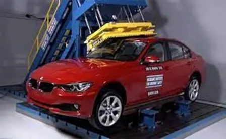
The Roof of a car is the component which encloses the passenger compartment from the top. It protects the Passengers and the interior of the car from external environments thus providing a safe and isolated cabin.
There are many divisios for a roof:
1.front roof rail
2.rear roof rail
3.center rail
4.bow roof rail
Types of Car Roofs:
- Convertible roofs.
- Hard Tops
- Sun roofs.
- T- Tops.
- Target tops.
- Vinyl roofs.
there are Design Consideration of roof:1
1.Visibility Criteria
2.Head Clearance
3.Curvature Study
4.Heat Distortion and snow load criteria
5.draft Analysis
6.Safety Parameters
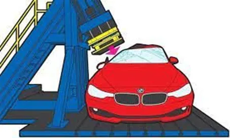
Roof crush test:
A crash test is a form of destructive testing usually performed in order to ensure safe design standards in crashworthiness and crash compatibility for various modes of transportation (see automobile safety) or related systems and components.
different types of crash test in india are
- Full Frontal (IS: 11939, ECE R12)
- Offset Frontal (AIS098, ECE R94)
- Side Impact (AIS099, ECE R95)
- Rear Impact (AIS101, ECE R34)
benefits of crash test:Along with testing the effectiveness of passive safety systems such as seat belts and airbags, the primary purpose of vehicle crash tests is to evaluate the deformation of the vehicle's passenger-carrying compartment in various collision scenarios
- Frontal-impact tests: which is what most people initially think of when asked about a crash test. Vehicles usually impact a solid concrete wall at a specified speed, but these can also be vehicle impacting vehicle tests. SUVs have been singled out in these tests for a while, due to the high ride-height that they often have.
- Moderate Overlap tests: in which only part of the front of the car impacts with a barrier (vehicle). These are important, as impact forces (approximately) remain the same as with a frontal impact test, but a smaller fraction of the car is required to absorb all of the force. These tests are often realized by cars turning into oncoming traffic. This type of testing is done by the U.S.A. Insurance Institute for Highway Safety (IIHS), Euro NCAP, Australasian New Car Assessment Program (ANCAP) and ASEAN NCAP.
- Small Overlap tests: this is where only a small portion of the car's structure strikes an object such as a pole or a tree, or if a car were to clip another car. This is the most demanding test because it loads the most force onto the structure of the car at any given speed. These are usually conducted at 15-20% of the front vehicle structure.
- Side-impact tests: these forms of accidents have a very significant likelihood of fatality, as cars do not have a significant crumple zone to absorb the impact forces before an occupant is injured.
- Pole-impact tests: A difficult test which places a large amount of force on a small proportion on the side of the vehicle.
- Roll-over tests: which tests a car's ability (specifically the pillars holding the roof) to support itself in a dynamic impact. More recently, dynamic rollover tests have been proposed in lieu of static crush testing (video).
- Roadside hardware crash tests: are used to ensure crash barriers and crash cushions will protect vehicle occupants from roadside hazards, and also to ensure that guard rails, sign posts, light poles and similar appurtenances do not pose an undue hazard to vehicle occupants.
- Old versus new: Often an old and big car against a small and new car, or two different generations of the same car model. These tests are performed to show the advancements in crash-worthiness.
- Computer model: Because of the cost of full-scale crash tests, engineers often run many simulated crash tests using computer models to refine their vehicle or barrier designs before conducting live tests.
- Sled testing: A cost-effective way of testing components such as airbags and seat belts is conducting sled crash testing. The two most common types of sled systems are reverse-firing sleds which are fired from a standstill, and decelerating sleds which are accelerated from a starting point and stopped in the crash area with a hydraulic ram. It can also be used to evaluate the whiplash protection of a vehicle's seat.
PROCEDURE:
our roof assembly is divided into mainly 6 parts
1.roof outer panel
2.front roof rail
3.bow roof 1
4.bow roof 2
5.rear roof rail
6.centre roof rail
ROOF OUTER PANEL
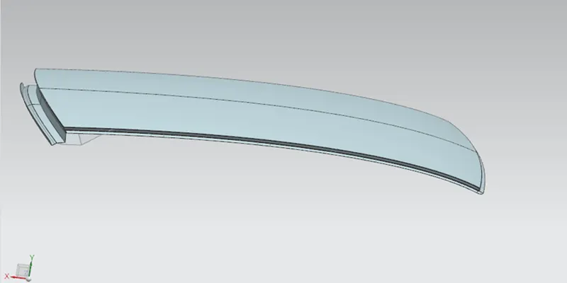
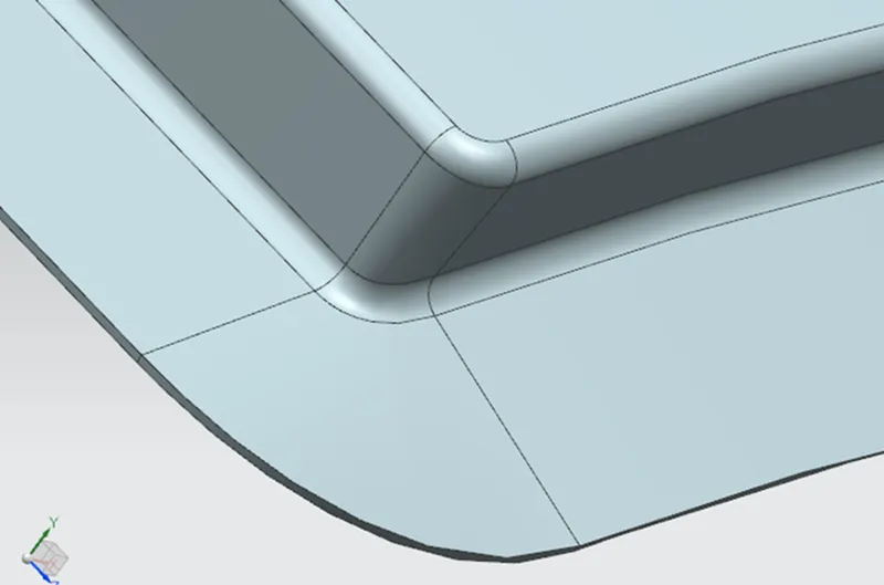
- The roof is diivided into 2 andone of the section is used to work based on the master sectio.
- at the front a law extension of 15mm at 97 degrees is made
- a law extension from the above curve is made of 21.5 mm at 97 degrees.
- for the side ditch a law extension from the roof of 15mm is made at 97 degrees.
- step 3 is repeated on step 4
- a law extension for the rear roof is made at 35mm at 65 degrees
- on the above curve a law extension of 45mm at 25 degrees is made.
- on the above curve a law extension of 40mm at 90 degrees is made.
- on the above curve a law extension of 25mm at 25 degrees is made.
- on the above curve a law extension of 25mm at 90 degrees is made
- the openings between the ditches are filled by the bridge curve and studeio surface
- the surfaces are sewed and given an edge fillet of 2.2 cm
- the whole shape is then sewed and mirrored
- the small opening after the miroor is troubleshoot using extend and trim.
- then its thickened by 7.5mm down
front roof rail 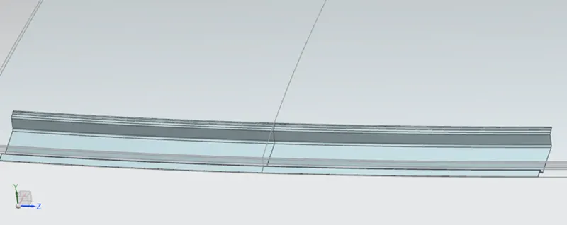
- the roof outer panel is extracted and off set at 15mm
- the roof is off set at 32 mm down
- the sheet is untrimmed
- from the step 1 extreacted a law wxtension at 25mm at 97 degrees is made
- a on curve datum plane is made on the roof and an intersection is made on to it.
- and the roof curve is proejected to a point on the previous arc
- wich is the n off set for 10mm and 15mm
- the above two curves are trimmed with the off set roof surface
- the offset suefaces are joined using the studio surface and joined
- they alla re then sewed
- the base edges are given a fillet of 5 mm and others at 3 mm
- it is then mirroredand sewed which gives the coorectly aligned surfaces
- the above surface is thickened at 0.75mm above
BOW ROOF 1 AND BOW ROOF 2
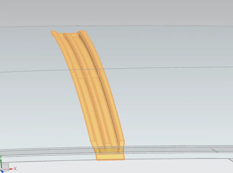
- roof is extraced
- roof is then offset at a distance of 6.5 and 20 mm down
- A datum plane is formed on the surface adn an intersection is made.
- which is then offset at a distance of 10,30, 40, 60 and 70mm
- the above offset curves are taken on trim with the off set surfaces.
- they are all sewed and given a edge blend of 2.2mm
- which is then offset and thickened.
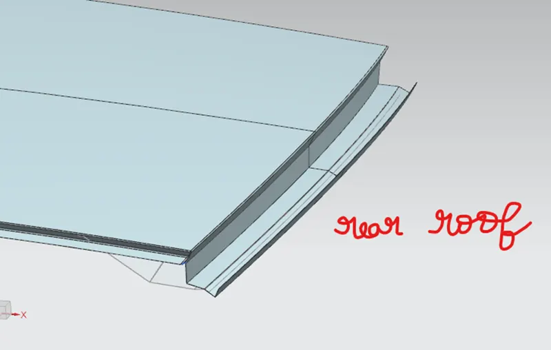
Rear roof rail:
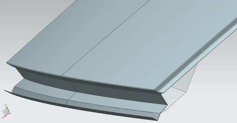
- The roof is projected
- the roof is offset at a distance of 4.5 ,6.5 and 90.7 mm
- the 90 mm offset is law extended with the spot welding surface offset which was offset at a distance of 1.5mm
- the 90.7 mm offset is law extended at 32 degrees with the 6.5 mm offset
- which is law extended with 4.5mm offset
- it is then sewed and thickened.
centre roof rail
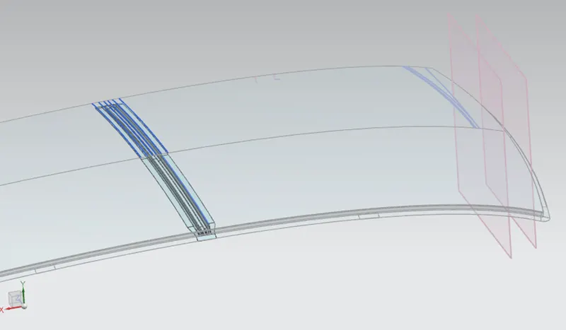
it is the same procedure as that of the bow roof but here the total length should be between 80-90
in centre roof the curve offset were all at a distance of 20 ,35,47.5,62 and 82
conclusion procedure :
all the surfaces are thickened to get the roof assembly+
the roof outer panel thickened at 0.75 mm down wards ,rest all 0.75 mm upwards.
Calculations:
W = [1.73 x 10^(-3) x L] + [1.85 x 10^(-8) x (R^2)/t] + [ 1.10x10^(-3) x l] - 2.68
Where,
L = Roof Length in X-Direction[mm](Roof dimension in 0-Y)=2028.40
R = Roof curvature
R = 2(Rx*Ry)/(Rx+Ry)=3036.07
Rx = X curvature=3071.95
Ry = Y curvature=3001.03
t = Roof plate thickness [mm]=1.5
l = Bow Roof Span [mm]=907.66
w=1.9412432<2.7(ok)
Qr = [Iy x t2] / [α x s x [(Rx + Ry)/2]2 x 10-8]
Note: The Qr value given over here is correct. There was a typo error in the formula given in the video.
Where,
α = My x Lx2 x 10-12 , My = Y(Ly-Y)
t = Roof plate thickness [mm]
Ly = Distance between the front and rear roof Rails on the Vehicle along with 0Y[mm]
Length of Roof panel with the center point between Roof rail Front /Rear as the front and rear reference point.
Lx = Distance between the Left and Right end of the roof on the Roof BOW [mm]
The width of the roof panel is exposed on the surface.
Y = Distance front Front Roof Rail to Roof BOW[mm]
s = Distance for which Roof BOW bears divided load [mm]
s = L1/2 + L2/2
Iy = Geometrical moment of inertia of Roof BOW (Y cross-section )[mm4]
Rx = Lateral direction curvature radius of roof panel Y cross-section on Roof BOW [mm]
Roof panel curvature Radius of the Length Lx in Front view
Ry = Longitudinal Direction curvature radius of the Roof panel X cross-section on Roof BOW [mm]
Roof panel X curvature radius of length s in Side view
Case1:
L1=530.4702
L2=488.8392
T=1.5
Y=530.4702
I=1.962193723
Lx=1144.8095
S=265.23+244.4196=509.6496
Qr=10>3
Case2:
L1=488.8392
L2=488.6422
Lx=1079.0101
Y=1081.0909
Iy=2.296360934
S=488
Qr=56.1
Case 3:
Iy=1.975717008
L1=488.6422
L2=365.7619
Y=1055.2979
S=422
Qr =48