Roof Design
OBJECTIVE
The main objective of this project is to develop the car roof design and its reinforcements from the given styling surface & Master section. And to prepare a detailed report about the engineering standards for roof design, its design procedure, Draft analysis and manufacturing techniques.
CAR ROOF
An Car roof is the portion of an automobile that sets above the passenger compartment, protecting the vehicle occupants from sun, wind, rain, and other external elements. Roof is the structure above the wind shield glass having the reinforcements to provide the strength to the overall structure and to with stand the over head forces like snow
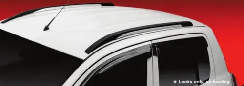
ROOF REINFORCEMENTS
If the roof is flat it is very weak and cannot able to with stand the forces like snow , so in order to increase the strength of the roof these reinforcements like front roof rail, central roof rail, rear roof rail and the bow roofs are introduced and joined to the flat surface of the roof with the different joining process
TYPES OF ROOF REINFORCEMENTS
- Front roof rail
- Bow roofs
- Central roof rail
- Rear roof rail
DESIGN CONSIDERATION OF CAR ROOF
- Visibility criteria
- Head room clearance
- Bow roof position
- Curvature study
- Heat distortion and Snow load criteria
- Draft analysis
DESIGN PROCEDURE
1. Roof outer frame
As per the given Class A surface and Master section mentioned in fornt & Rear roof rail, Roof outer frame is designed
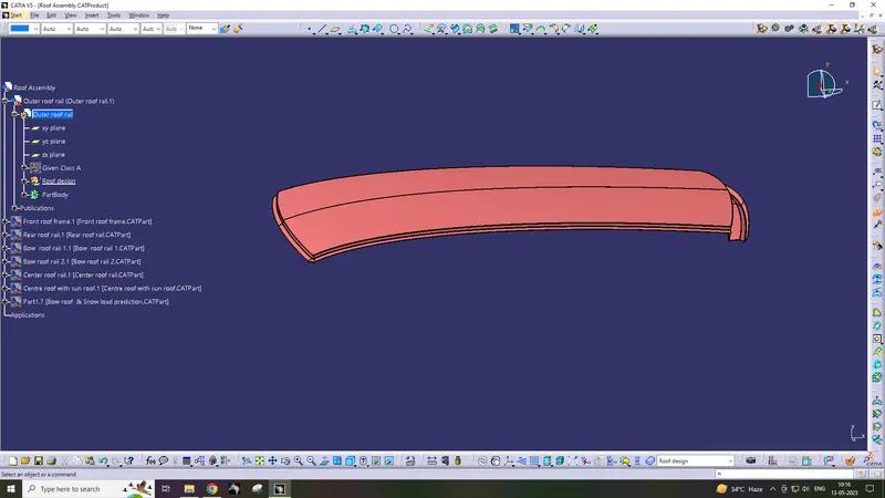
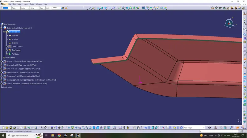
Front end flange
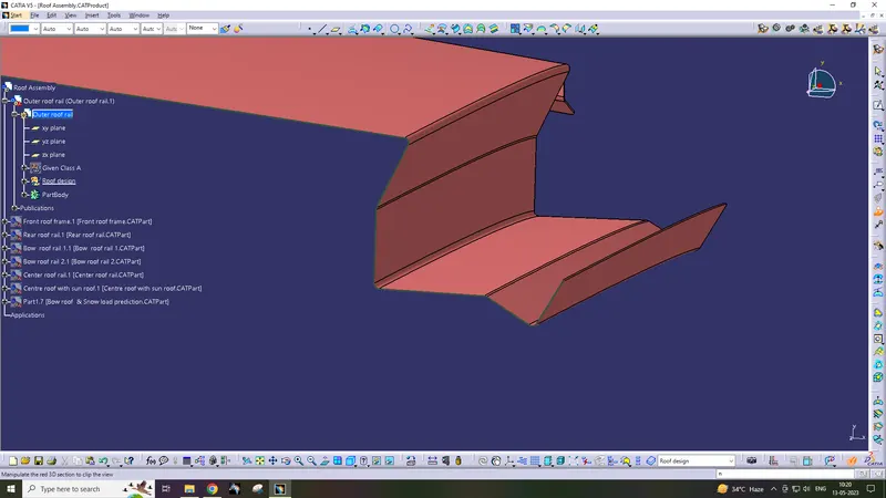
Rear end flange
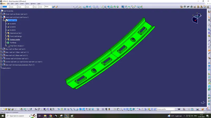
2.Front roof rail design
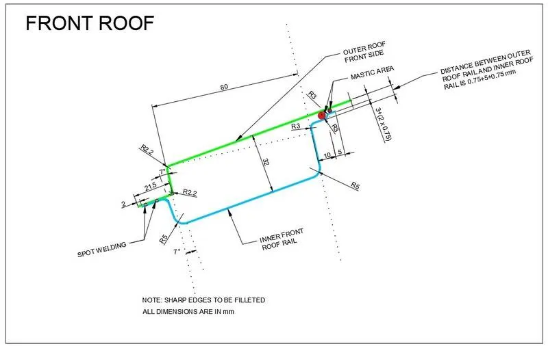
As per the Master section given above, we deisgn the Front roof rail
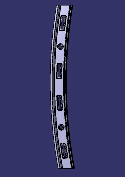
Emboss profile was added with front roof rail for better strength
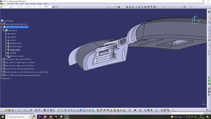
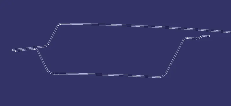
Intersect profile with roof outer frame
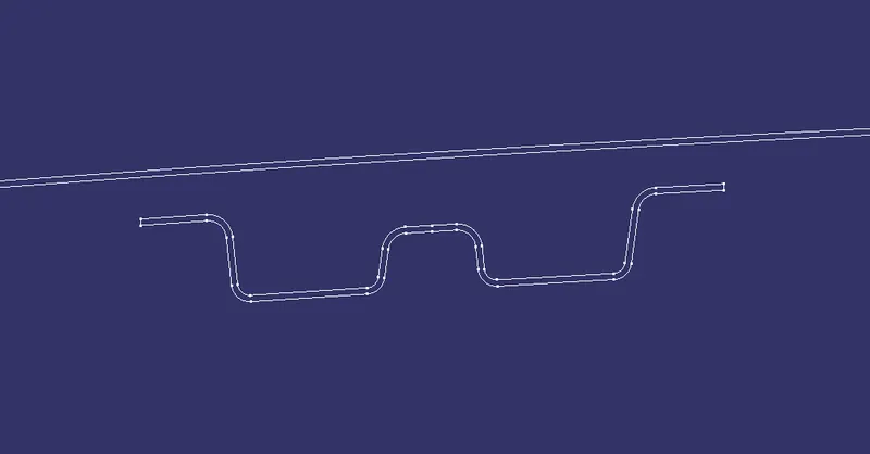
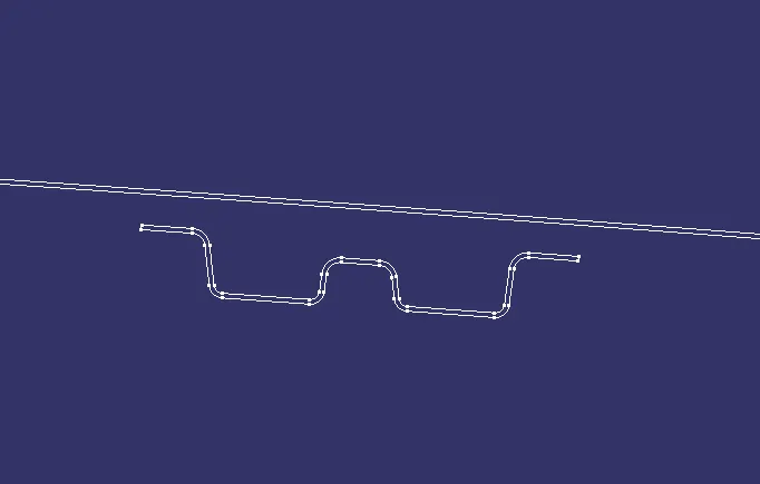
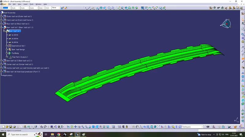
3.Bow roof rail design
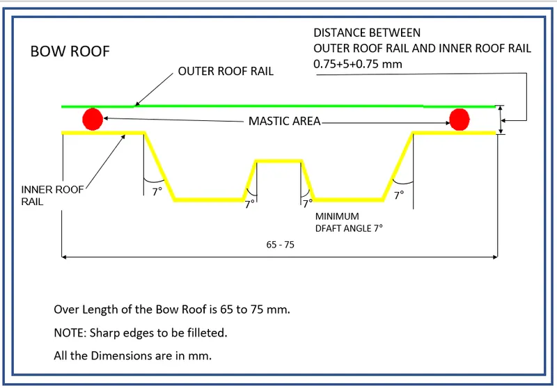
As per the Master section given above, we deisgn the 2 Bow roof rails. one bow roof is placed in between Front roof rail & Center roof rail.
other bow roof is placed between center roof rail & Rear roof rail
Bow roof rail-1:

Bow roof rail-2:

Intersect profile with roof outer frame
Bow roof rail-1:
Bow roof rail-2:
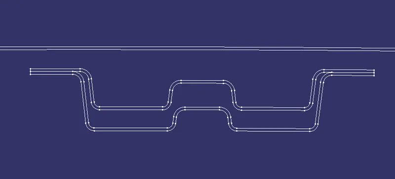
4. Center Roof rail
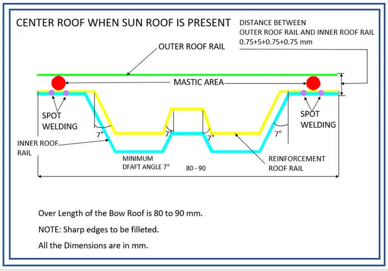
As per the Master section given above, we deisgn the Centre roof rail

Section view:
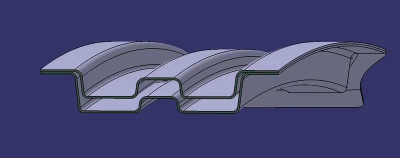
Intersect profile with roof outer frame
5. Rear roof rail design
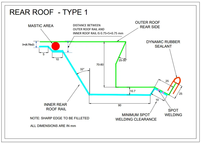
As per the Master section given above, we deisgn the Rear roof rail
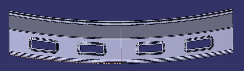
Emboss profile was added with front roof rail for better strength
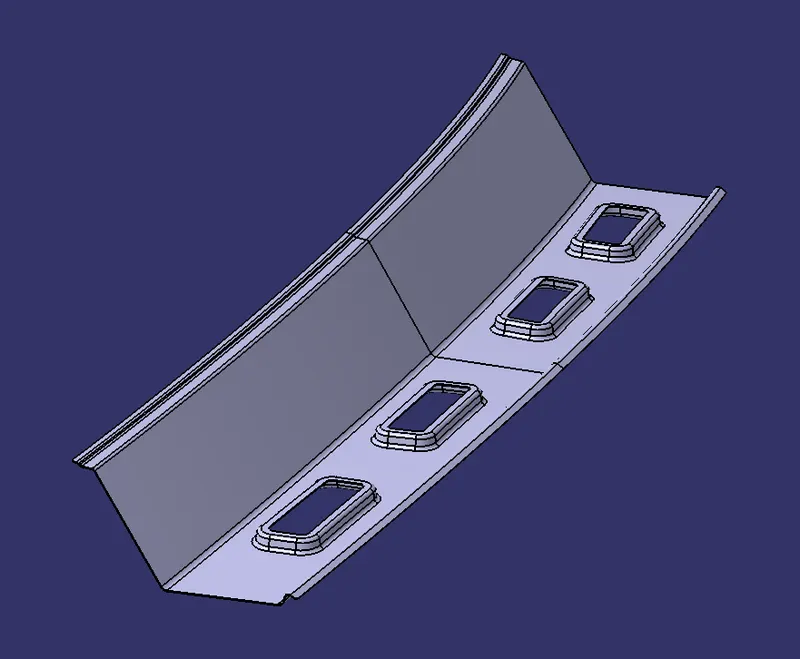
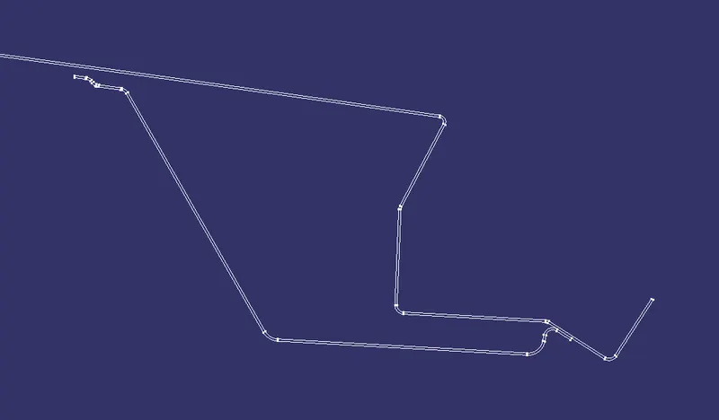
Intersect profile with roof outer frame
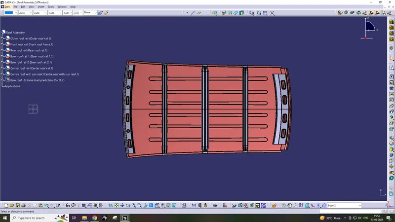
Complete Roof design
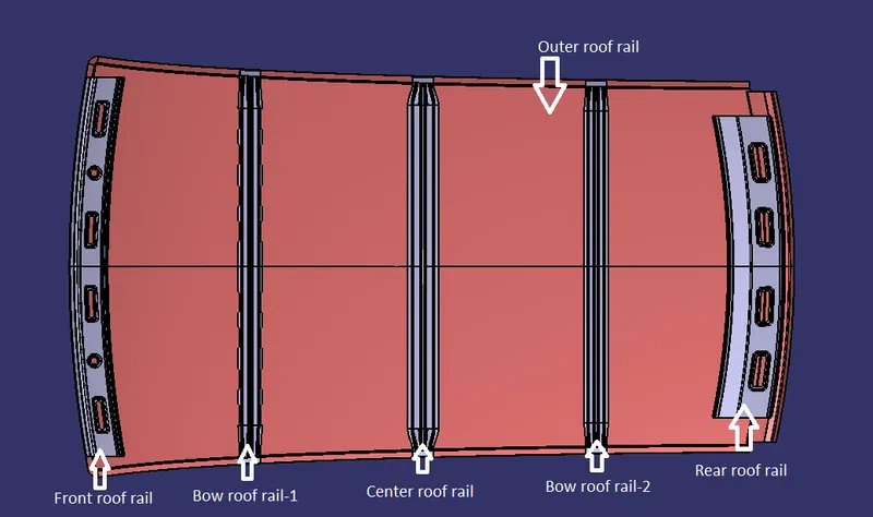
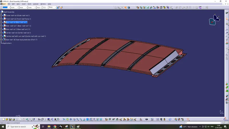
All edges are fillet for smooth surface
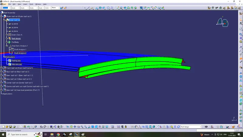
DRAFT ANALYSIS
1. Roof outer frame
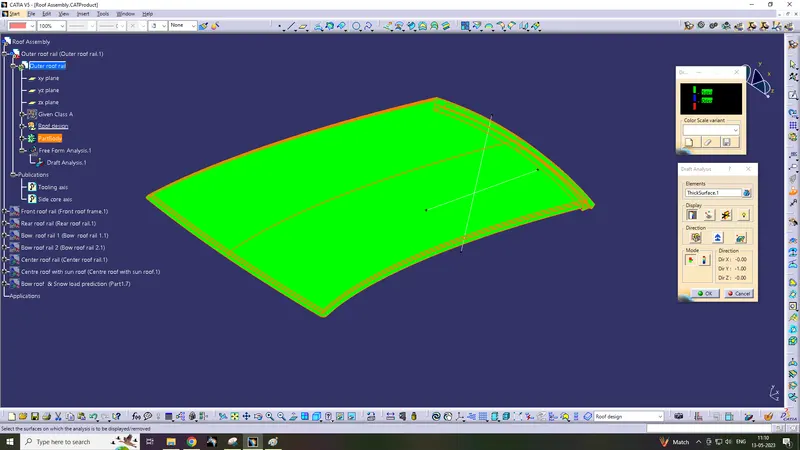
Here we have side core axis, because rear end has undercut value
2.Front roof rail design
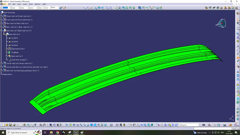
3.Bow roof rail design
Bow roof rail-1
Bow roof rail-2
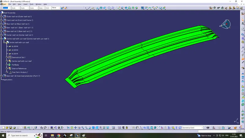
4. Center Roof rail
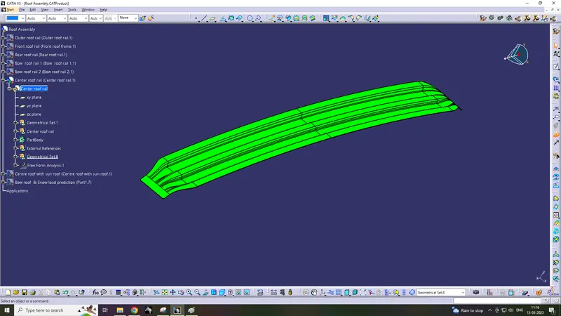
Second layer of center roof rail
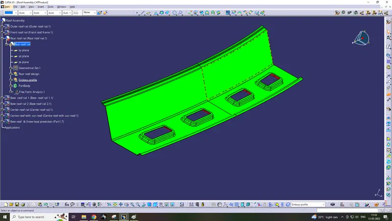
5. Rear roof rail design
SECTION MODULUS
S = I/y
Where,
S = Section Modulus
I = Moment of Inertia
y = distance between the neutral axis and the extreme end of the object
1.Front roof rail
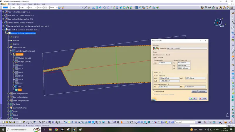
| Min I = | 0.00002296 | mm4 |
| Max I = | 0.000177 | mm4 |
| y = | 61.4395 | mm |
| Min S = | 3.73701E-07 | mm3 |
| Max S = | 2.88088E-06 | mm3 |
2.Bow roof rail-1
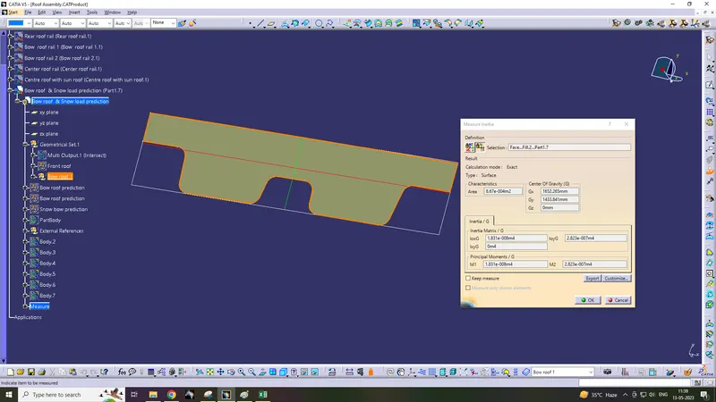
| Min I = | 1.877E-05 | mm4 |
| Max I = | 0.0002823 | mm4 |
| y = | 35.053 | mm |
| Min S = | 5.356E-07 | mm3 |
| Max S = | 8.054E-06 | mm3 |
3. Center roof rail
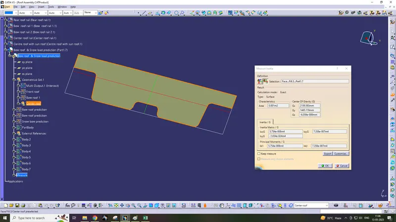
| Min I = | 0.0000574 | mm4 |
| Max I = | 0.0007358 | mm4 |
| y = | 45.0345 | mm |
| Min S = | 1.275E-06 | mm3 |
| Max S = | 1.634E-05 | mm3 |
4.Bow roof rail-2
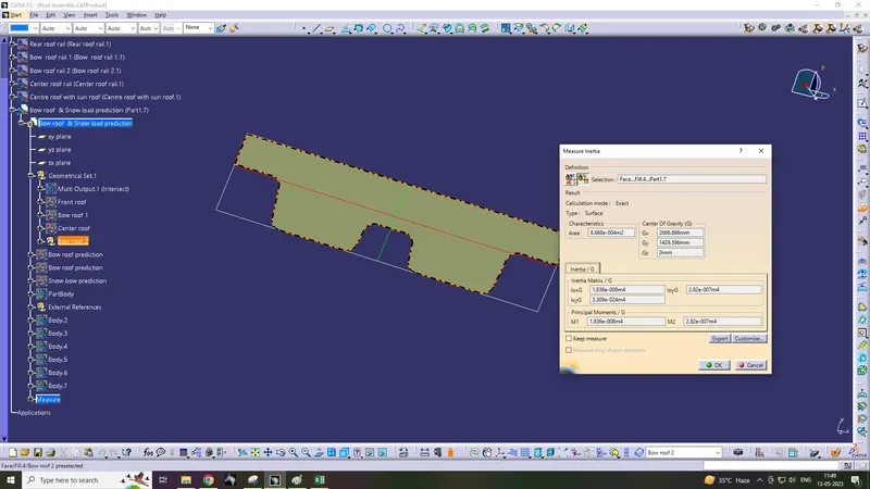
| Min I = | 1.836E-05 | mm4 |
| Max I = | 0.000282 | mm4 |
| y = | 35.0015 | mm |
| Min S = | 5.245E-07 | mm3 |
| Max S = | 8.057E-06 | mm3 |
5.Rear roof rail
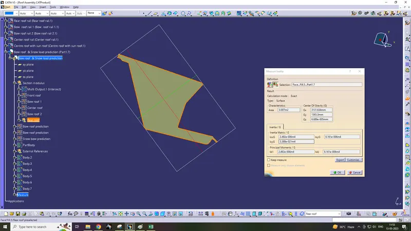
| Min I = | 0.002492 | mm4 |
| Max I = | 0.008161 | mm4 |
| y = | 93.677 | mm |
| Min S = | 2.66E-05 | mm3 |
| Max S = | 8.712E-05 | mm3 |
ROOF DESIGN CALCULATION
- Heat distortion criteria
- Snow load criteria
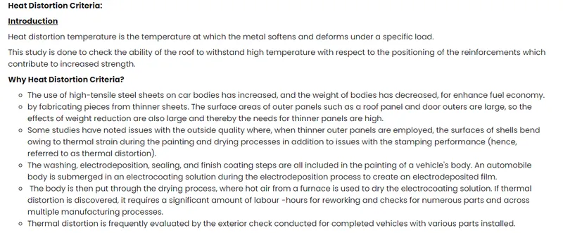
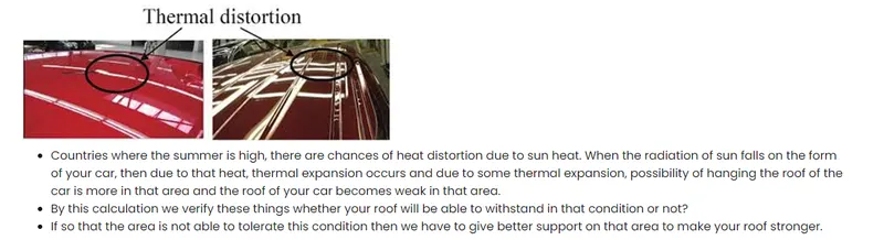
W = [1.73 x 10^(-3) x L] + [1.85 x 10^(-8) x (R^2)/t] + [ 1.10x10^(-3) x l] - 2.68
Where,
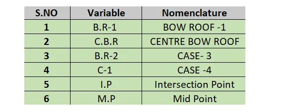
L = Roof Length in X-Direction[mm](Roof dimension in 0-Y)
R = Roof curvature
R = 2(Rx*Ry)/(Rx+Ry)
Rx = X curvature
Ry = Y curvature
t = Roof plate thickness [mm]
l = Bow Roof Span [mm]
Judgment Condition
OK< 2.7
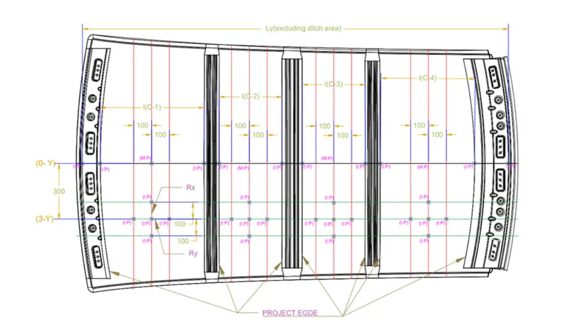
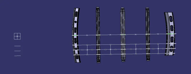
so, for calculate Heat distortion criteria, we need to draw a sketch to create particular points what we required to measure & calculate,
Step-1:
Create a offset plane at 300mm from X-Y plane.
Step-2:
and again offset the plane 100mm on both side
Step-3:
intersect the Roof assembly by using these 3 planes
Step-4:
create a sketch & create mid points which in between the space of all reinforcement
Step-5:
from every midpoint create a vertical line on both sides at 100mm
Step-6:
now intersect the vertical line intersect the intersection profile which we create in step-3
Step-7:
Start create intersect points as shown below
Step-8:
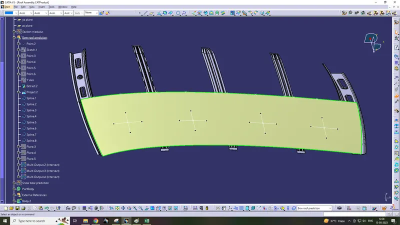
extract the top surface of roof outer rail & Project these point on the extract surface
Step-9:
For measure the Rx & Ry, create a arc on that required intersect point
Step-10:
Then calculate the W by using these parameter
W = [1.73 x 10^(-3) x L] + [1.85 x 10^(-8) x (R^2)/t] + [ 1.10x10^(-3) x l] - 2.68
Where,
L = Roof Length in X-Direction[mm](Roof dimension in 0-Y)
R = Roof curvature
R = 2(Rx*Ry)/(Rx+Ry)
Rx = X curvature
Ry = Y curvature
t = Roof plate thickness [mm]
l = Bow Roof Span [mm]
Judgment Condition
OK< 2.7

Here, All reinforcement judgement condition are below 2.7.
So, our design is satisfied as per the heat distortion prediction, All reinforcement are placed at the right position.
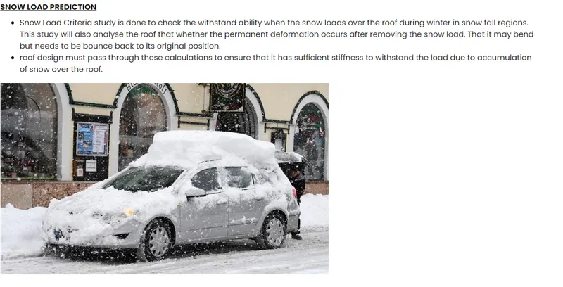
Snow Load Prediction Formula
Qr = [Iy x t2] / [α x s x [(Rx + Ry)/2]2 x 10-8]
Note: The Qr value given over here is correct. There was a typo error in the formula given in the video.
Where,
α = My x Lx2 x 10-12 , My = Y(Ly-Y)
t = Roof plate thickness [mm]
Ly = Distance between the front and rear roof Rails on the Vehicle along with 0Y[mm]
Length of Roof panel with the center point between Roof rail Front /Rear as the front and rear reference point.
Lx = Distance between the Left and Right end of the roof on the Roof BOW [mm]
The width of the roof panel is exposed on the surface.
Y = Distance front Front Roof Rail to Roof BOW[mm]
s = Distance for which Roof BOW bears divided load [mm]
s = L1/2 + L2/2
Iy = Geometrical moment of inertia of Roof BOW (Y cross-section )[mm4]
Rx = Lateral direction curvature radius of roof panel Y cross-section on Roof BOW [mm]
Roof panel curvature Radius of the Length Lx in Front view
Ry = Longitudinal Direction curvature radius of the Roof panel X cross-section on Roof BOW [mm]
Roof panel X curvature radius of length s in Side view
Judgment condition
Qr ≥ 3.1
so, for calculate Snow load criteria, we need to draw a sketch to create particular points what we required to measure & calculate,
Step-1:
Create a offset plane with respect to X-Y plane at 100mm on both side
Step-2:
intersect the Roof assembly by using these 3 planes
Step-3:
Create Intersect points by using X-Y plane & all reinforcement edges
Step-4:
create a midpoint in between the all reinforcement
Step-5:
from every midpoint create a vertical line through out the outer roof surface
Step-6:
now offset the vertical lines at 100mm on both sides
Step-7:
Start create intersect points as shown below
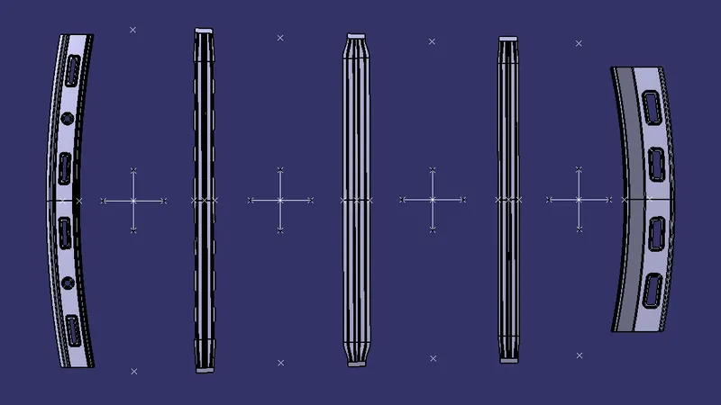
Step-8:
extract the top surface of roof outer rail & Project these point on the extract surface
Step-9:
For measure the Rx & Ry, create a arc on that required intersect point
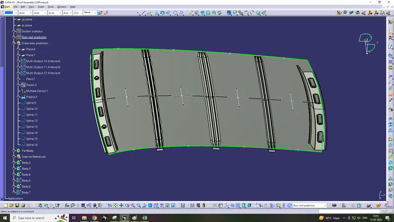
Step-10:
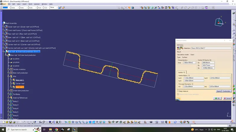
Iy are calculated by X-Y plane intersection area of reinforcement & minimum value is taken for calculation
Bow roof -1
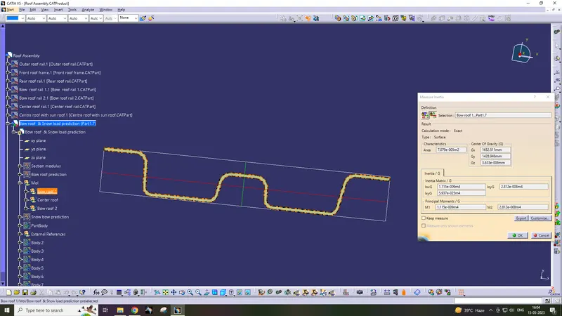
Center roof
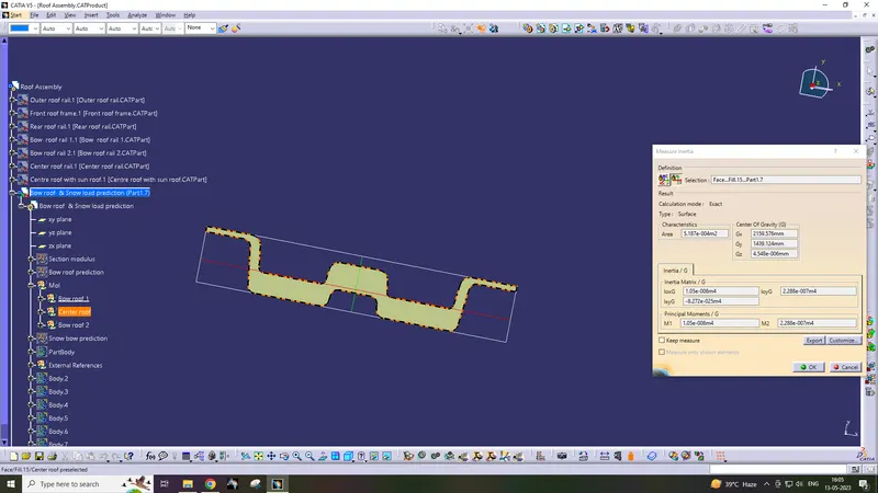
Bow roof - 2
Step-11:
Then calculate the Qr by using these parameter
Qr = [Iy x t2] / [α x s x [(Rx + Ry)/2]2 x 10-8]
Note: The Qr value given over here is correct. There was a typo error in the formula given in the video.
Where,
α = My x Lx2 x 10-12 , My = Y(Ly-Y)
t = Roof plate thickness [mm]
Ly = Distance between the front and rear roof Rails on the Vehicle along with 0Y[mm]
Length of Roof panel with the center point between Roof rail Front /Rear as the front and rear reference point.
Lx = Distance between the Left and Right end of the roof on the Roof BOW [mm]
The width of the roof panel is exposed on the surface.
Y = Distance front Front Roof Rail to Roof BOW[mm]
s = Distance for which Roof BOW bears divided load [mm]
s = L1/2 + L2/2
Iy = Geometrical moment of inertia of Roof BOW (Y cross-section )[mm4]
Rx = Lateral direction curvature radius of roof panel Y cross-section on Roof BOW [mm]
Roof panel curvature Radius of the Length Lx in Front view
Ry = Longitudinal Direction curvature radius of the Roof panel X cross-section on Roof BOW [mm]
Roof panel X curvature radius of length s in Side view
Judgment condition
Qr ≥ 3.1

Here, Bow roof -2 judgement condition not achieved the required target, others are satisfied.
So, we have to do some modification in design
According to fulfill the condition, we can modify
- Need to change position for Bow roof 2
- By increasing thickness or width
- can give addition bow roof
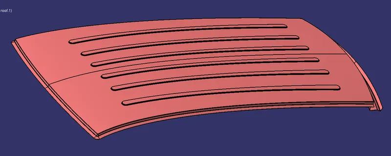
- Additional embosses to be provided on Outer roof rail
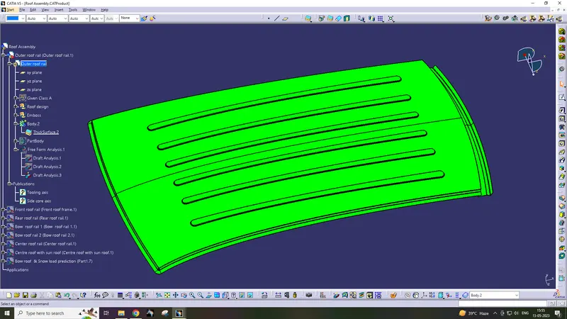
Here, we are providing Additional embosses on Outer roof panel to increase the strength to withstand the snow load.
Darft analysis
MANUFACTURING PROCESS
Metal stamping process is commonly used in automotive vehicle body manufacturing by OEM.
Metal stamping process
The process of turning sheets of metal into a useful part or component is called sheet metal stamping. The metal is fed into a press, where the stamping tool, also known as a die, creates the desired shape. The die is pressed into or through the metal with tremendous force.
Common Sheet metal stamping process:
There are basically only three components to sheet metal stamping—the sheet metal, die, and press machine—but any single part can require multiple steps to arrive at its final form. The following guide explains a few common processes that might occur during metal stamping.
- Forming: Forming describes the process of transforming the flat metal into another shape by applying force. It is accomplished in one of several ways, depending on the design specifications for the part. With a series of operations, the metal can be altered from a relatively simple shape into a complex one.
- Blanking: Blanking is the most basic technique and initiates when the sheet or blank is fed into the press where the die cuts out the desired shape. The resulting piece is called a blank. The blank may be the desired part, also known as a fully finished blank, or it may continue to the subsequent step of forming.
- Drawing: Drawing is a more complicated operation and is how vessels or deep depressions are formed. Tension is used to carefully draw the material into a cavity to change its shape. Though the material might stretch while it’s drawn, technicians try to avoid stretching as much as possible to keep the material intact. Sinks, cooking equipment, and oil pans for vehicles are usually made with drawing.
- Piercing: Piercing is almost the opposite of blanking, but instead of saving the blanks, technicians use the material around the outside of the punched area. As an example, think of cutting biscuits from a rolled-out circle of dough. During blanking, the biscuits are saved; during piercing, on the other hand, the biscuits are discarded, and the hole-riddled remains are the desired outcome.
CONCLUSION
The car roof design and its reinforcements were developed from the given styling surface. and I have done the draft analysis for the same. Also Calculating the heat distortion and snow roof calculations for the roof design, here I have got that in the snow roof calculation the bow roof -2 section is not fullfilling the judgement condition. so, I have provided the emboss on the roof outer panel to increase the strength of the outer panel.